Velkase Velka 3 User manual

1
2/NOV/2020
VELKA 3
Rev 2.0
USER MANUAL
Specification................................................................................................................................................. 2
Hardware compatibility............................................................................................................................. 3
Summary of assembly steps ....................................................................................................................... 4
Disassembly ................................................................................................................................................. 5
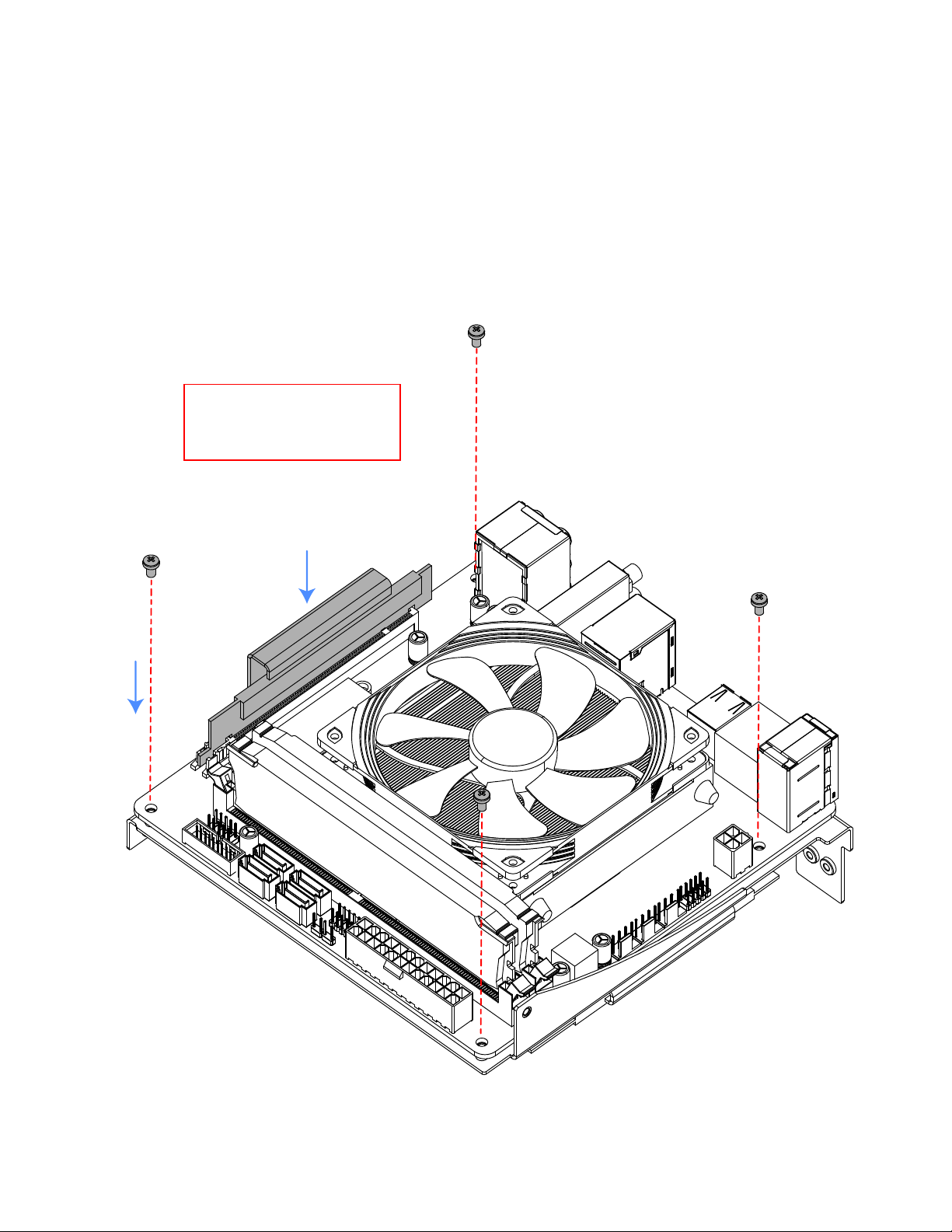
CPU, memory, M.2 drive, and motherboard installation ...................................................................... 6
Graphics card .............................................................................................................................................. 7
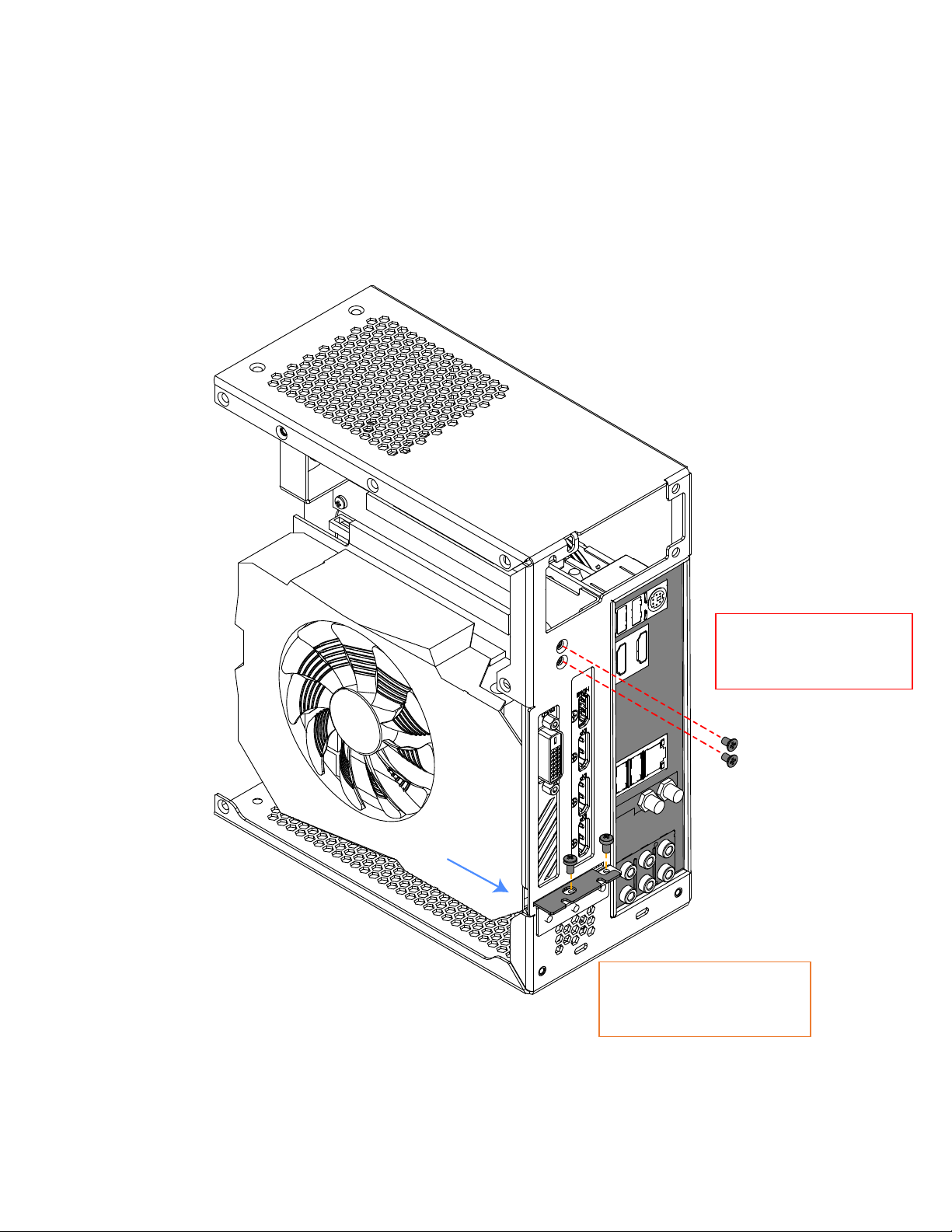
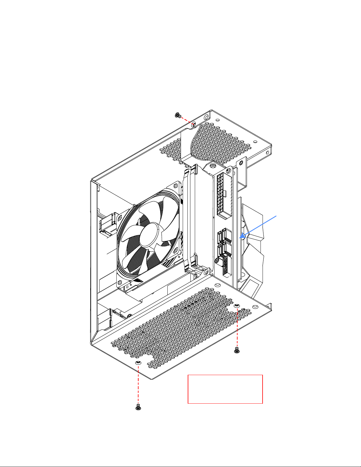
Installation into the main body ................................................................................................................. 8
Power supply ............................................................................................................................................. 10
2.5” drive (dedicated mount) .................................................................................................................. 11
Front struts ................................................................................................................................................ 12
Power button............................................................................................................................................. 14
Side panels ................................................................................................................................................. 15
Front panel ................................................................................................................................................ 17

2
2/NOV/2020
SPECIFICATION
Dimensions
(L x W x H)
189 x 96 x 218 mm
Weight
1.5 kg
With included power supply: 2.6 kg
Volume (liters)
3.9 L external, 3.7 L internal
Materials and finish
5 mm anodized and sandblasted aluminum front panel
1.2 mm powder-coated galvanized steel and stainless
steel body
1.0 mm powder-coated galvanized steel side panels
I/O
Front: N/A
Top: N/A
Rear: Motherboard, graphics
Security
Kensington Lock Slot
PCIe riser
PCIe 3.0 x16

3
2/NOV/2020
HARDWARE COMPATIBILITY
Motherboard
Mini ITX
170 x 170 mm
Power supply
ENP-7660B (optional)
Replaceable with Flex ATX (150 mm)
CPU cooler
37 mm
Graphics card
(L x W x H)
Maximum clearance, including cables. Cables
require 16 mm if not recessed into the board.
175 x 43 x 148 mm
178 x 40 x 148 mm
Memory
42 mm
Storage
1x 2.5” HDD or SSD (7.0 mm thick)
Case fans
N/A

4
2/NOV/2020
SUMMARY OF ASSEMBLY STEPS
Before starting assembly in the case, test all other components for functionality. If using a
PCIe gen 4 graphics card and motherboard with the included PCIe gen 3 riser, the
compatibility mode must be set to gen 3 in BIOS. Doing so will require performing the
first boot with integrated graphics (if available) or with the graphics card plugged directly
into the motherboard without a riser.
1. Install your CPU, CPU cooler, memory, and M.2 drive onto the motherboard, attach it to
the tray
2. Insert riser into the PCIe slot, flip over the tray, install graphics card and screw in riser
3. Install IO shield and install that subassembly back into the main body of the case with the
top PSU holder attached
4. Install power supply, 2.5” drive, attach all cables
5. Install front struts, install power button into the front panel and plug it in without
installing the front panel, install side panels, then the front panel

5
2/NOV/2020
DISASSEMBLY
It is recommended to work with the case on a soft surface such as the
included foam until rubber feet are installed.
1
2
2
3
4

6
2/NOV/2020
CPU, MEMORY, M.2 DRIVE, AND MOTHERBOARD
INSTALLATION
Install the CPU, cooler, memory, and M.2 drive onto the motherboard.
Attach the motherboard to the tray and plug in the included PCIe riser.
4x round head 5 mm
M3 screws

7
2/NOV/2020
GRAPHICS CARD
Screw in the PCIe riser on the opposite side and connect the graphics card.
Graphics card IO shield
must be on the outside of
the part highlighted in red
as shown
2x round head 5 mm
M3 screws

8
2/NOV/2020
INSTALLATION INTO THE MAIN BODY
Insert the subassembly from the previous step into the frame.
2x round head 5 mm
M3 screws
2x countersunk 5
mm M3 screws

9
2/NOV/2020
Screw in middle subassembly with all components at the bottom and on the
left side. Only screw in the right screw after installing the power supply.
3x countersunk 5
mm M3 screws

10
2/NOV/2020
POWER SUPPLY
Slide in the power supply in the orientation shown and only attach it to the
main body with the middle screw. Screw in the last PSU holder screw only
after installation, otherwise, the PSU may not slide in easily.
1x round head 6
mm 6-32 screw
1x countersunk 5
mm M3 screw

11
2/NOV/2020
2.5” DRIVE (DEDICATED MOUNT)
Slide in the 2.5” drive from the front and secure it to the main body of the
case. Connect all cables after this step.
3x countersunk 5 mm
M3 screws

12
2/NOV/2020
FRONT STRUTS
All cables must be plugged in before this step. Complete the main body by
installing the two struts in the front.
4x countersunk 5 mm
M3 screws

13
2/NOV/2020

14
2/NOV/2020
POWER BUTTON
Remove the bottom bracket temporarily to install the power button. Use the
hex nut to fix the button in place, then reinstall the bottom bracket.
Consult your motherboard manual for the front panel header pin layout and
plug in the power button before proceeding to the next step.
Button is enlarged for clarity. Hold the
button from the opposite side and secure
it using the nut without the rubber ring.
This step will require some force.
1
2

15
2/NOV/2020
SIDE PANELS
Power button cables must be plugged into the motherboard prior to this step.
The side panels have three positions. Spacing them farther away from the
body of the case will result in quieter operation.
0 mm spacing
2 mm spacing (experimental)
4 mm spacing (experimental)
If using the experimental 2 or 4 mm
spacing, adhesive rubber feet may be
inserted between the side panel
and main body to help keep
the side panels straight.
6x countersunk 5 mm
M3 screws

16
2/NOV/2020
2x round head or
countersunk 5 mm M3 screws
3x 6-32 screws

17
2/NOV/2020
FRONT PANEL
Slide in the front panel while carefully inserting the power button’s cable into
the case. Secure the front panel to the frame at the bottom and the top.
For an easier fit, re-position the brackets on the inside of the front panel
away from the edges.
Install the included rubber feet after this step.
4x countersunk 5 mm
M3 screws
Other manuals for Velka 3
2
Table of contents
Other Velkase Enclosure manuals
Popular Enclosure manuals by other brands

EMC
EMC VNXe3100 Replacing Manual

L-Acoustics
L-Acoustics KARA MODULAR WST SYSTEM Rigging Procedures

StarTech.com
StarTech.com S3520WU33ER Spec sheet

Moog Videolarm
Moog Videolarm PDDW10CN2 Installation and operation instructions

Black Box
Black Box IE PowerTray 18-Slot AC manual

COUGAR
COUGAR MG110-W user manual