Seagull Models NEMESIS User manual

1
ASSEMBLY MANUAL
Code : SEA 114
Specications:
Wingspan---------------80.5 in--------------(204.5cm)
Wing area---------------1069.5--------------sq.ins (69 sq.dm)
Weight-------------------11.9-13.2 lbs------(7.6kg)
Length-------------------64.3 in -------------(163.4 cm)
Engine/Motor size---------------------------50-60cc gasoline
Radio---------------------5 channels with 6 servos

NEMESIS Instruction Manual.
2
ank you for choosing the NEMESIS ARTF by SG MODELS . e NEMESIS was de-
signed with the intermediate/advanced sport yer in mind. It is a semi scale airplane which
is easy to y and quick to assemble. e airframe is conventionally built using balsa, ply-
wood to make it stronger than the average ARTF, yet the design allows the aeroplane to be
kept light. You will nd that most of the work has been done for you already. e motor
mount has been tted and the hinges are pre-installed. Flying the NEMESIS is simply a joy.
is instruction manual is designed to help you build a great ying aeroplane. Please read
this manual throughly before starting assembly of your NEMESIS Use the parts listing be-
low to indentify all parts.
Please be aware that this aeroplane is not a toy and if assembled or used incorrectly it is ca-
pable of causing injury to people or property. WHEN YOU FLY THIS AEROPLANE YOU
ASSUME ALL RISK & REPONSIBILITY.
If you are inexperienced with basic R/C ight we strongly recommend you contact your R/C
supplier and join your local R/C model Flying Club. R/C Model Flying Clubs oer a variety
of training procedures designed to help the new pilot on his way to successful R/C ight.
ey will also be able to advise on any insurance and safety regulations that may apply.
INTRODUCTION
WARNING
KIT CONTENTS
1
22
11 13
3 3
4
5
6
78
9
10
12
3
ADDITIONAL ITEMS REQUIRED
TOOLS & SUPPLIES NEEDED
in cyanoacrylate glue.
Medium cyanoacrylate glue.
30 minute epoxy.
5 minute epoxy.
Hand or electric drill.
Assorted drill bits.
Modelling knife.
Straight edge ruler.
2mm ball driver.
Phillips head screwdriver.
220 grit sandpaper.
90° square or builder’s triangle.
Wire cutters.
Masking tape & T-pins.
read-lock.
Paper towels.
�50-60cc gasoline engine.
�Computer radio 5 channel with 6
servos.
�Glow plug to suit engine.
�Propeller to suit engine.
�Protective foam rubber for radio
system.
KIT CONTENTS
SEA114 NEMESIS
1. Fuselage
2. Wing set (2)
3. Tail set (2)
4. Canopy
5. Cowling
6. Wing tube
7. Landing gear
8. Tail wheel
9. Fuel tank
10. Pushrod set
11. Ep Motor box
12. Pilot
13. Spinner
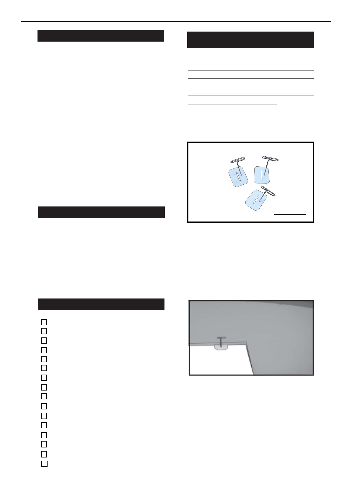
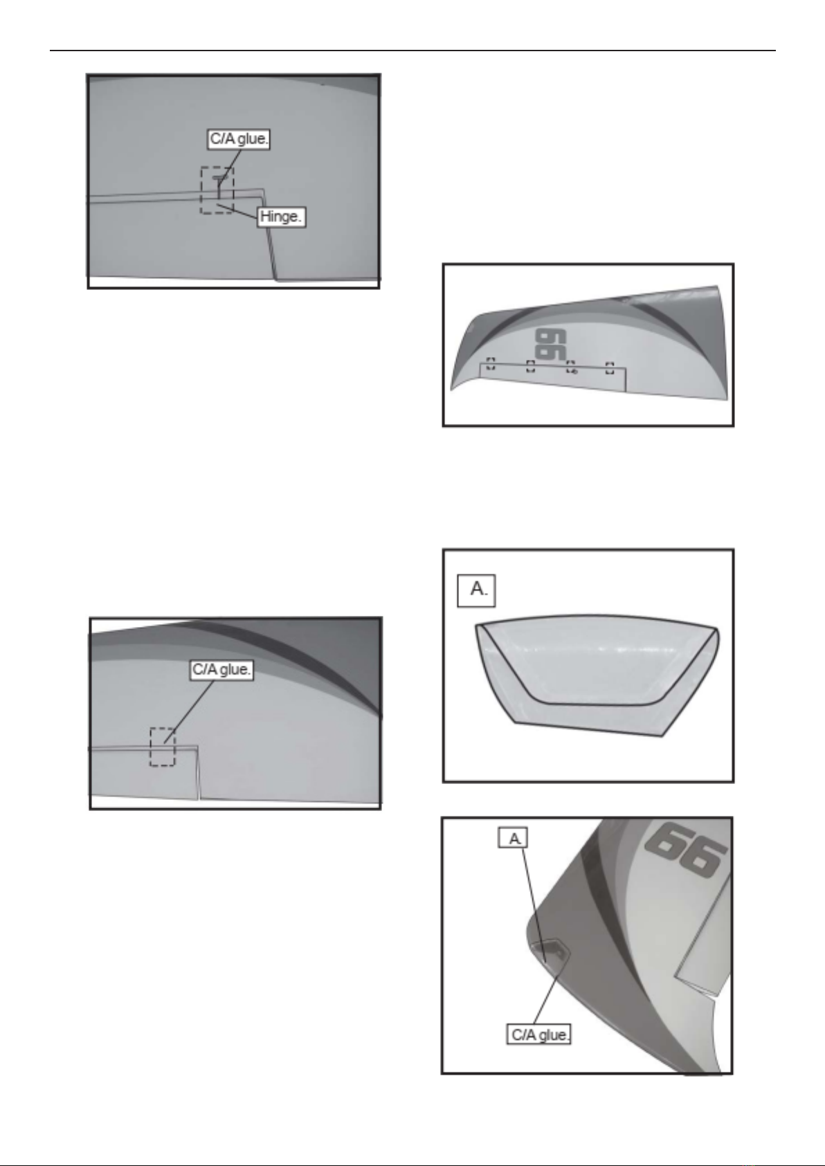
HINGING THE AILERON
Note : e control surfaces, including the ailer-
ons, elevators, and rudder, are prehinged with
hinges installed, but the hinges are not glued in
place. It is imperative that you properly adhere
the hinges in place per the steps that follow us-
ing a high-quality thin C/A glue.
Carefully remove the aileron from one of
the wing panels. Note the position of the
hinges.
1.
C/A Hinge
Remove each hinge from the wing panel
and aileron and place a T-pin in the center
of each hinge. Slide each hinge into the wing
panel until the T-pin is snug against the wing
panel. is will help ensure an equal amount
of hinge is on either side of the hinge line
when the aileron is mounted to the aileron.
Slide the wing panel on the aileron until
there is only a slight gap. e hinge is now
centered on the wing panel and aileron.
Remove the T-pins and snug the aileron
against the wing panel. A gap of 1/64” or
less should be maintained between the
wing panel and aileron.
2.
NEMESIS Instruction Manual.
4
NOTE : e hinge is constructed of a spe-
cial material that allows the C/A to wick
or penetrate and distribute throughout
the hinge, securely bonding it to the wood
structure of the wing panel and aileron.
Deect the aileron and completely satu-
rate each hinge with thin C/A glue. e
ailerons front surface should lightly con-
tact the wing during this procedure. Ide-
ally, when the hinges are glued in place,
a 1/64” gap or less will be maintained
throughout the lengh of the aileron to the
wing panel hinge line.
Turn the wing panel over and deect the
aileron in the opposite direction from the
opposite side. Apply thin C/A glue to each
hinge, making sure that the C/A penetrates
into both the aileron and wing panel.
Using C/A remover/debonder and a paper
towel, remove any excess C/A glue that may
have accumulated on the wing or in the
aileron hinge area.
Repeat this process with the other wing
panel, securely hinging the aileron in
place.
Aer both ailerons are securely hinged,
rmly grasp the wing panel and aileron to
make sure the hinges are securely glued
and cannot be pulled out. Do this by care-
fully applying medium pressure, trying to
separate the aileron from the wing panel.
Use caution not to crush the wing struc-
ture.
Work the aileron up and down sev-
eral times to “work in” the hinges
and check for proper movement.
Note :
3.
5.
6.
7.
4.
5
Locate the aileron and ap control horns.
e taller control horn is used for the ailer-
ons, and the shorter horn for the aps.
Use sandpaper to scu the bottom of the
aileron and ap control horns. Use a paper
towel and isopropyl alcohol to remove any
oils or debris from the control horns.
Check the t of the control horns to the
aileron and ap. ey should rest ush
against the control surface as shown.
INSTALL THE AILERONS
CONTROL HORN
1.
2.
Ailerons control horn
3.
Place low-tack tape 1/32 inch (1mm)
from the control horn slot. is will pre-
vent epoxy from getting on the control
surface when the control horns are glued
in place.
Remove the control horns from the
control surfaces. Apply epoxy to the slot
in the aileron and ap. Make sure the
epoxy gets into the slot for a good bond
between the surfaces and control horn.
4.
5.
Epoxy
Apply epoxy to the area of the control
horns that st into the slots. Use enough
epoxy so the control horns will be fully
bonded to the ed surfaces.

NEMESIS Instruction Manual.
6
Before the epoxy fully cures, remove
the tape from around the control horn.
is will allow the epoxy to ow around
the control horn, creating a small let
between the control horn and surface for
a ished look and secure bond.
7.
6.
Epoxy
Because the size of servos dier, you
may need to adjust the size of the precut
opening in the mount. e notch in the
sides of the mount allow the servo lead to
pass through.
Place the servo between the mounting
blocks and space it from the hatch. Use
a pencil to mark the mounting hole loca-
tions on the blocks.
INSTALLING THE AILERON SERVOS
Use drill bit in a pin vise to drill the
mouting holes in the blocks.
1.5mm
3.
4.
2.
1.
20.0
Minimum servo spec.
Torque : 6.0V: 192.4 oz-in (13.8 kg-cm)
7.4V: 350.0 oz-in (25.2 kg-cm)

7
Use dental oss or heatshrink tube to
secure the connection so they cannot be-
come unplugged.
C/A glue
5.
6.
Apply 2-3 drops of thin C/A to each of
the mounting holes. Allow the C/A to
cure without using accelerator.
Secure the servo to the aileron hatch
using Phillips screwdriver and the screws
provided with the servo.
Apply 1-2 drops of thin C/A to each of
the mounting tabs. Allow the C/A to cure
without using accelerator.
Remove the string from the wing at the
servo location and use the tape to attach it
to the servo extension lead. Pull the lead
through the wing and remove the string.
C/A glue
7.
8.
9.
10.

NEMESIS Instruction Manual.
8
Hex nut
Set the aileron hatch in place and use a
Phillips screw driver to install it with four
wood screws.
11.
12.
3x10mm
13.
14.
AILERON PUSHROD INSTALLATION
- Please study images below.
75mm
2.
1.
M3 clevis M3 lock nut
3.
4.
M3 clevis
Fuel tubing
Hex nut

9
INSTALLING LANDING GEAR
Locate items necessary to install Sprin
Landing Gear.
1.
3.
2.
4.
5.
6.
7.
M3x4mm.
Collar.
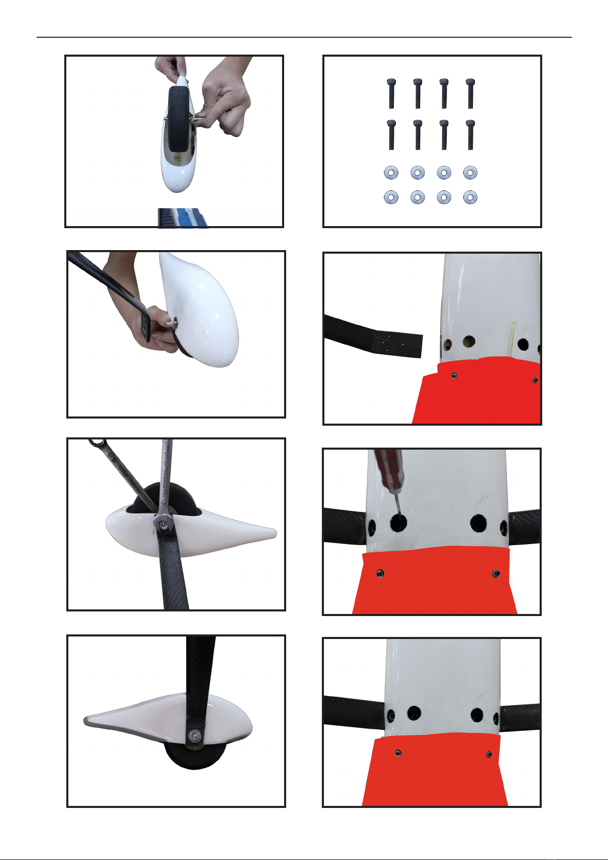
NEMESIS Instruction Manual.
10
9.
8.
10.
11.
12.
13.
14.
15.
11
.
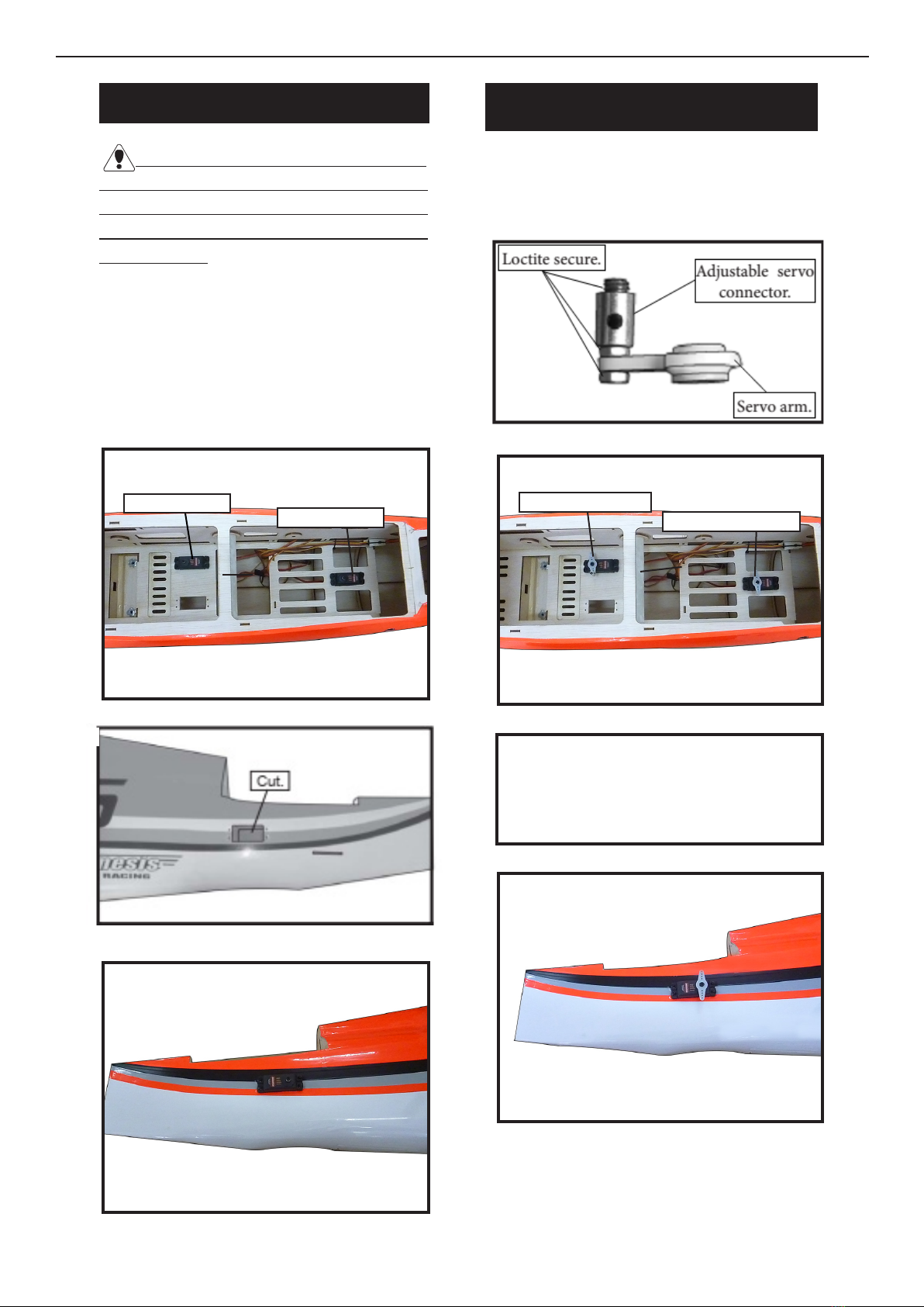
INSTALLING THE FUSELAGE SERVOS
.
Because the size of servos dier, you
may need to adjust the size of the precut
opening in the mount. e notch in the
sides of the mount allow the servo lead to
pass through.
Install the rubber grommets and brass
collets into all servos. Test t the servos
into the fuselage servo mounts.
Secure the servos with the screws
provided with your radio system.
1.
3.
Rudder servo
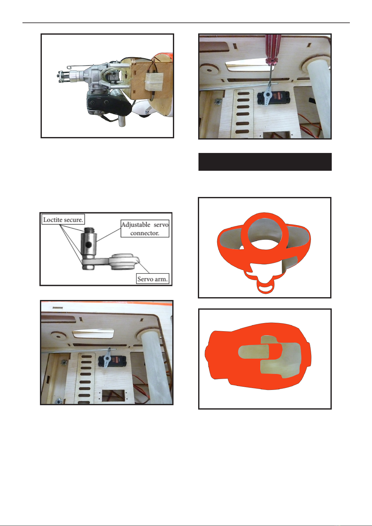
THROTTLE SERVO ARM
INSTALLATION
Install adjustable servo connector in the
servo arm as same as picture below:
2.
3.
Rudder servo arm
1.
rottle servo rottle servo arm
2.
Minimum servo spec.
Torque : 6.0V: 192.4 oz-in (13.8 kg-cm)
7.4V: 350.0 oz-in (25.2 kg-cm)

NEMESIS Instruction Manual.
12
INSTALLING THE SWITCH
Install the switch into the precut hole in
the side, in the fuselage.
3/32” Hole.
1.
4.
5.
2.
3.
INSTALLING THE STOPPER
ASSEMBLY
Using a modeling knife, carefully cut
o the rear portion of one of the 3 nylon
tubes leaving 1/2” protruding from the
rear of the stopper. is will be the fuel
pick up tube.
Using a modeling knife, cut one length
of silicon fuel line. Connect one end of
the line to the weighted fuel pick up and
the other end to the nylon pick up tube.
1.

13
2.
Carefully bend the second nylon tube up at
a 45º angle. is tube is the vent tube.
3.
Test t the stopper assembly into the tank.
It may be necessary to remove some of the
ashing around the tank opening using a
modeling knife. If ashing is present, make
sure none falls into the tank.
FUEL TANK INSTALLATION
When satised with the alignment of the
stopper assembly tighten the 3x20mm ma-
chine screw until the rubber stopper expands
and seals the tank opening. Do not overtight-
en the assembly as this could cause the tank
to split.
With the stopper assembly in place, the
weighted pick-up should rest away from the
rear of the tank and move freely inside the
tank. e top of the vent tube should rest just
below the top of the tank. It should not touch
the top of the tank.
1.
Fuel pick up tube.Vent tube.
Fuel lltube.
Slide the fuel tank into the fuselage. Guide
the lines from the tank through the hole in
the ewall.
You should mark which tube is the vent
and which is the fuel pickup when you attach
fuel tubing to the tubes in the stopper. Once
the tank is installed inside the fuselage, it may
be dicult to determine which is which.
2.
3.

NEMESIS Instruction Manual.
14
7.
6.
4.
5.
8.
Fuel pick up tube. Fuel ll tube.
Vent tube.
Connect the lines from the tank to the
engine and muer. e vent line will
connect to the muer and the line from
the clunk tothe carburetor.
Blow through one of the lines to ensure
the fuel lines have not become kinked inside
the fuel tank compartment. Air should ow
through easily.
MOUNTING THE ENGINE
Please see below pictures.
1.
2.

15
4.
3.
5.
6.
7.
8.
9.
5x90mm
10.
NEMESIS Instruction Manual.
16
11.
12.
13.
180mm
15.
16.
17.
18.14.
Ignition Modude
17
19.
20.
Reinstall the servo horn by sliding the
connector over the pushrod wire. Center
the throttle stick and trim and install the
servo horn perpendicular to the servo
center line.
Move the throttle stick to the closed po-
sition and move the carburetor to closed.
Use a 2.5mm hex wrench to tighten the
screw that secures the throttle pushrod
wire. Make sure to use threadlock on the
screw so it does not vibrate loose.
21.
22.
COWLING
- Please see below pictures.
2.
1.
Tape the cowl to the fuselage using low-
tack tape.
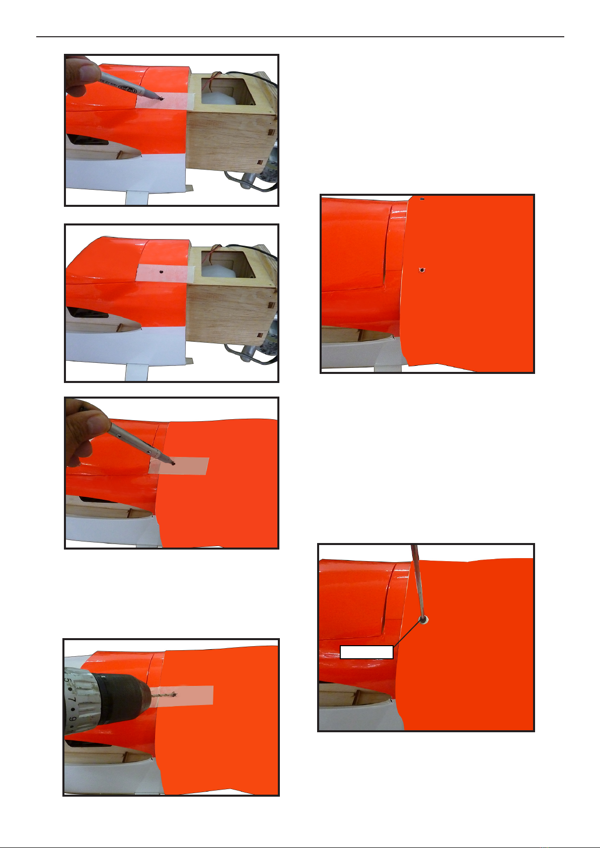
NEMESIS Instruction Manual.
18
3.
4.
5.
Use a drill and drill bit to drill the holes
for the cowl mounting screws. Make sure
the cowl position is correct before drill-
ing each hole.
With the muer, needle valve, and spark/
glow plug removed from the engine, slide
the cowl in place over the engine. Tem-
porarily install the propeller and spinner
in order to d the exact location of the
cowl. When satised with the cowl place-
ment, secure the cowl to the fuselage us-
ing masking tape.
Install the muer and muer extension
onto the engine and make the cutout in
the cowl for muer clearance. Connect
the fuel and pressure lines to the carbu-
retor, muer and fuel ler valve. Secure
the cowl to fuselage using the M3x10mm
socket head screws. Putting a small length
of silicon fuel tube under the head of the
screw helps with vibration.
6.
7.
M3x10mm
8.

19
1.
Recommend the items necessary to
install the electric power conversion parts
included with your model.
ELECTRIC POWER CONVERSION
Locate the items neccessary to install the
electric power conversion included with
your model.
Because of the size of the cowl, it may be nec-
essary to use a needle valve extension for the
high speed needle valve. Make this out of suf-
cient length 1.5mm wire and install it into
the end of the needle valve. Secure the wire in
place by tightening the set screw in the side of
the needle valve.
9.
12.
13.
10.
11.

NEMESIS Instruction Manual.
20
3.
2.
Attach the electric motor box to the re-
wall centered with the cross lines drawn
on the electric motor box and rewall.
Using M6x25mm to secure the motor box
to the rewall. Please see pictures below.
4.
6.
5.
7.
- Motor: 360 - 6000 Watts
- Propeller: 24x10 ~ 25x12
- ESC: 160A - 200A
- 12S Lipo
This manual suits for next models
1
Table of contents
Other Seagull Models Aircraft manuals


Popular Aircraft manuals by other brands


Cessna
Cessna 172SPHUSR05 Pilot operating handbook

Ozone
Ozone Slalom Pilot's manual

Grob
Grob Astir CS G102 Flight manual

Thrush Aircraft
Thrush Aircraft S2R-T660 Maintenance manual

Ozone
Ozone Addict 2 Pilot's manual

Piper Aircraft Corporation
Piper Aircraft Corporation ARCHER II PA-28-181 Operating handbook


