Seagull Models Magic Bird SEA 380 User manual

1
ASSEMBLY MANUAL
Code : SEA 380
Specications:
Wingspan--------------- 45.67 in------------------ 116.0 cm.
Wing area--------------- 417.9 sq.in-------------- 27.0 sq.dm.
Weight------------------- 4.0 lbs-------------------- 1.8 kg.
Length------------------- 42 in --------------------- 106.8 cm.
Engine------------------- 32-37 cu.in.
Radio-------------------- 4 channels with 5 servos.

Magic Bird 46” EF1 Racer/Sport Plane ARF size .32-37 Instruction Manual.
2
ank you for choosing the Magic Bird 46” EF1 Racer/Sport Plane ARF size .32-
37 ARTF by SG MODELS . e Magic Bird 46” EF1 Racer/Sport Plane ARF size
.32-37 was designed with the intermediate/advanced sport yer in mind. It is a semi
scale airplane which is easy to y and quick to assemble. e airframe is convention-
ally built using balsa, plywood to make it stronger than the average ARTF, yet the de-
sign allows the aeroplane to be kept light. You will nd that most of the work has been
done for you already. e motor mount has been tted and the hinges are pre-installed.
Flying the Magic Bird 46” EF1 Racer/Sport Plane ARF size .32-37 is simply a joy.
is instruction manual is designed to help you build a great ying aeroplane. Please read
this manual throughly before starting assembly of your Magic Bird 46” EF1 Racer/Sport
Plane ARF size .32-37 Use the parts listing below to indentify all parts.
Please be aware that this aeroplane is not a toy and if assembled or used incorrectly it is ca-
pable of causing injury to people or property. WHEN YOU FLY THIS AEROPLANE YOU
ASSUME ALL RISK & REPONSIBILITY.
If you are inexperienced with basic R/C ight we strongly recommend you contact your R/C
supplier and join your local R/C model Flying Club. R/C Model Flying Clubs oer a variety
of training procedures designed to help the new pilot on his way to successful R/C ight.
ey will also be able to advise on any insurance and safety regulations that may apply.
INTRODUCTION
WARNING
KIT CONTENTS
1
22
3
3
4
5
8
12
6
9
10
11
13
7
3
ADDITIONAL ITEMS REQUIRED
TOOLS & SUPPLIES NEEDED
in cyanoacrylate glue.
Medium cyanoacrylate glue.
30 minute epoxy.
5 minute epoxy.
Hand or electric drill.
Assorted drill bits.
Modelling knife.
Straight edge ruler.
2mm ball driver.
Phillips head screwdriver.
220 grit sandpaper.
90° square or builder’s triangle.
Wire cutters.
Masking tape & T-pins.
read-lock.
Paper towels.
�32-37 cu.in gasoline engine.
�Computer radio 4 channel with 5
servos.
�Glow plug to suit engine.
�Propeller to suit engine.
�Protective foam rubber for radio
system.
KIT CONTENTS
SEA380 Magic Bird 46” EF1 Racer/
Sport Plane ARF size .32-37
1. Fuselage
2. Wing set (2)
3. Tail set (2)
4. Canopy
5. Cowling
6. Wing tube
7. Landing gear
8. Tail wheel
9. Fuel tank
10. Pushrod set
11. Ep Motor box
12. Pilot
13. Spinner
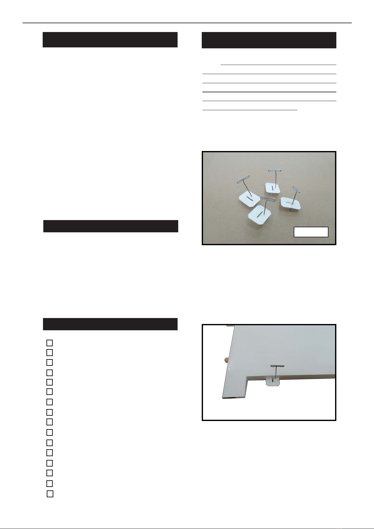
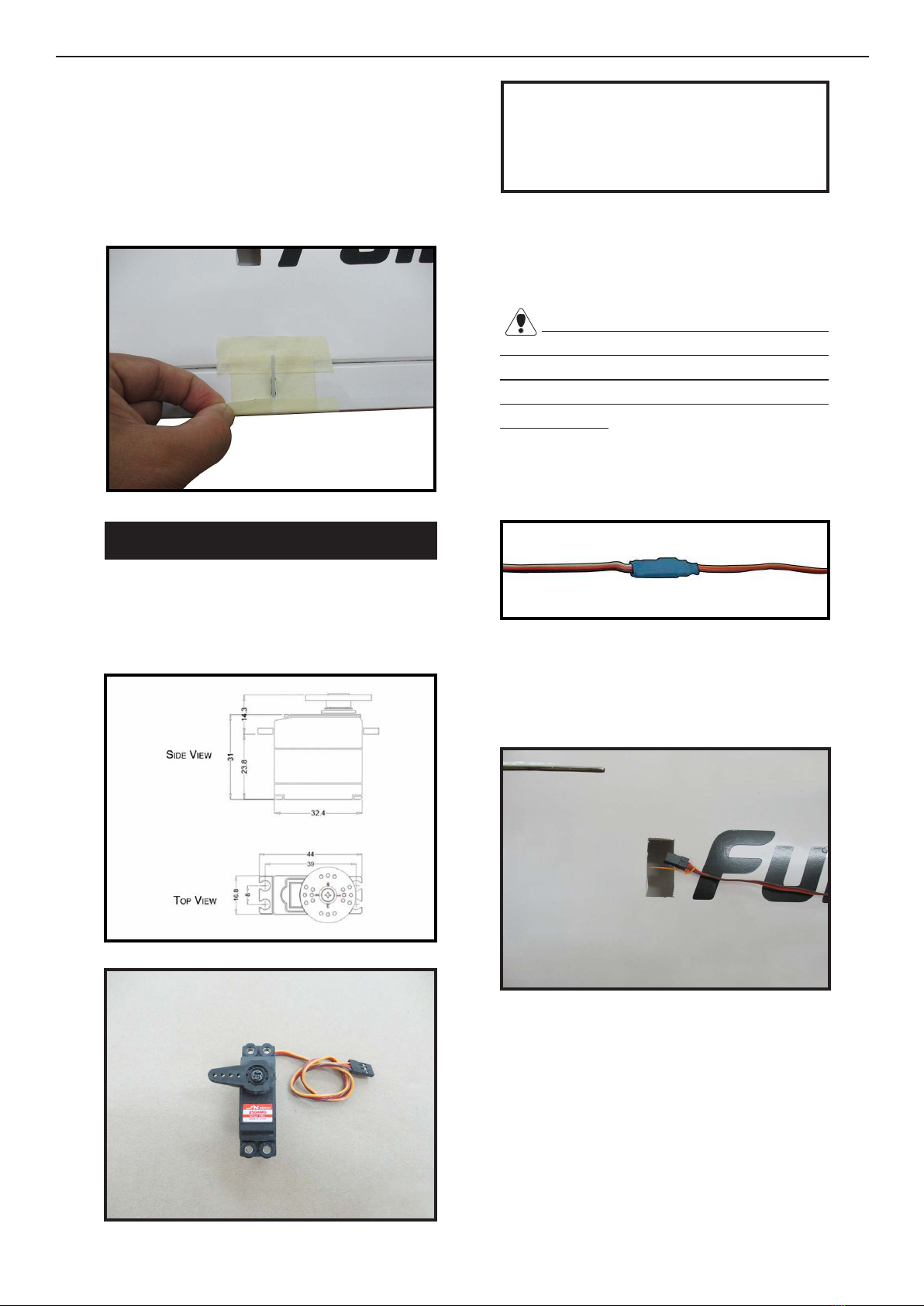
HINGING THE AILERON
Note : e control surfaces, including the ailer-
ons, elevators, and rudder, are prehinged with
hinges installed, but the hinges are not glued in
place. It is imperative that you properly adhere
the hinges in place per the steps that follow us-
ing a high-quality thin C/A glue.
Carefully remove the aileron from one of
the wing panels. Note the position of the
hinges.
1.
C/A Hinge
Remove each hinge from the wing panel
and aileron and place a T-pin in the center
of each hinge. Slide each hinge into the wing
panel until the T-pin is snug against the wing
panel. is will help ensure an equal amount
of hinge is on either side of the hinge line
when the aileron is mounted to the aileron.
Slide the wing panel on the aileron until
there is only a slight gap. e hinge is now
centered on the wing panel and aileron.
Remove the T-pins and snug the aileron
against the wing panel. A gap of 1/64” or
less should be maintained between the
wing panel and aileron.
2.

Magic Bird 46” EF1 Racer/Sport Plane ARF size .32-37 Instruction Manual.
4
6.
7.
3.
4.
5.
NOTE : e hinge is constructed of a spe-
cial material that allows the C/A to wick
or penetrate and distribute throughout
the hinge, securely bonding it to the wood
structure of the wing panel and aileron.
Deect the aileron and completely saturate
each hinge with thin C/A glue. e ailerons
front surface should lightly contact the wing
during this procedure. Ideally, when the
hinges are glued in place, a 1/64” gap or less
will be maintained throughout the lengh of
the aileron to the wing panel hinge line.
Turn the wing panel over and deect the
aileron in the opposite direction from the
opposite side. Apply thin C/A glue to each
hinge, making sure that the C/A penetrates
into both the aileron and wing panel.
Using C/A remover/debonder and a paper
towel, remove any excess C/A glue that may
have accumulated on the wing or in the
aileron hinge area.
Repeat this process with the other wing
panel, securely hinging the aileron in place.
Aer both ailerons are securely hinged,
rmly grasp the wing panel and aileron to
make sure the hinges are securely glued and
cannot be pulled out. Do this by carefully ap-
plying medium pressure, trying to separate
the aileron from the wing panel. Use caution
not to crush the wing structure.
Work the aileron up and down sev-
eral times to “work in” the hinges
and check for proper movement.
Note :
CA glue
Hinge

5
Locate the aileron control horns. e taller
control horn is used for the ailerons, and the
shorter horn for the aps.
Use sandpaper to scu the bottom of the
aileron and ap control horns. Use a paper
towel and isopropyl alcohol to remove any
oils or debris from the control horns.
Check the t of the control horns to
the aileron and ap. ey should rest ush
against the control surface as shown.
INSTALL THE AILERONS
CONTROL HORN
1.
2.
3.
Ailerons control horn
Place low-tack tape 1/32 inch (1mm)
from the control horn slot. is will pre-
vent epoxy from getting on the control
surface when the control horns are glued
in place.
Apply epoxy to the area of the control
horns that st into the slots. Use enough
epoxy so the control horns will be fully
bonded to the ed surfaces.
Remove the control horns from the
control surfaces. Apply epoxy to the slot
in the aileron and ap. Make sure the
epoxy gets into the slot for a good bond
between the surfaces and control horn.
4.
5.
Epoxy
6.
Epoxy
Magic Bird 46” EF1 Racer/Sport Plane ARF size .32-37 Instruction Manual.
6
Before the epoxy fully cures, remove
the tape from around the control horn.
is will allow the epoxy to ow around
the control horn, creating a small let
between the control horn and surface for
a ished look and secure bond.
Some mini servos you can use like.
Hitec HS - 225MG
JX Servo / PDI-2504MG / 25g
INSTALLING THE AILERON SERVOS
Because the size of servos dier, you
may need to adjust the size of the precut
opening in the mount. e notch in the
sides of the mount allow the servo lead to
pass through.
Install the rubber grommets and brass
collets onto the aileron servo. Test t the
servo into the aileron servo mount.
7.
1.
2.
Use dental oss to secure the connec-
tion so they cannot become unplugged.
Using a small weight (Weighted fuel
pickup works well) and thread, feed the
string through the wing as indicated.
3.
Attach servo lead to the aileron servo.
Attach the string to the servo lead and
carefully thread it though the wing. Once
you have thread the lead throught the
wing, remove the string so it can use for
the other servo lead.
4.
Mininum servo spec.
Torque : 54 oz-in (3.9 kg-cm) @ 4.8V;
67 oz-in (4.8 kg-cm) @ 6.0V
7
Tape the servo lead to the wing to pre-
vent it from falling back into the wing.
5.
Reinstall the servo into the servo mount
and secure the servo inplace using the
wood screws provided with you radio
system.
Repeat the procedure for the other wing
half.
Use a felt tip pen to mark the wire where
it crosses the hole. Use a pair of pliers to
put a shrp 90-degree bend in the wire at
the mark.
6.
7.
8.
9.
10.
AILERON PUSHROD INSTALLATION
Please study images below.
1.

Magic Bird 46” EF1 Racer/Sport Plane ARF size .32-37 Instruction Manual.
8
7.
2.
3.
.
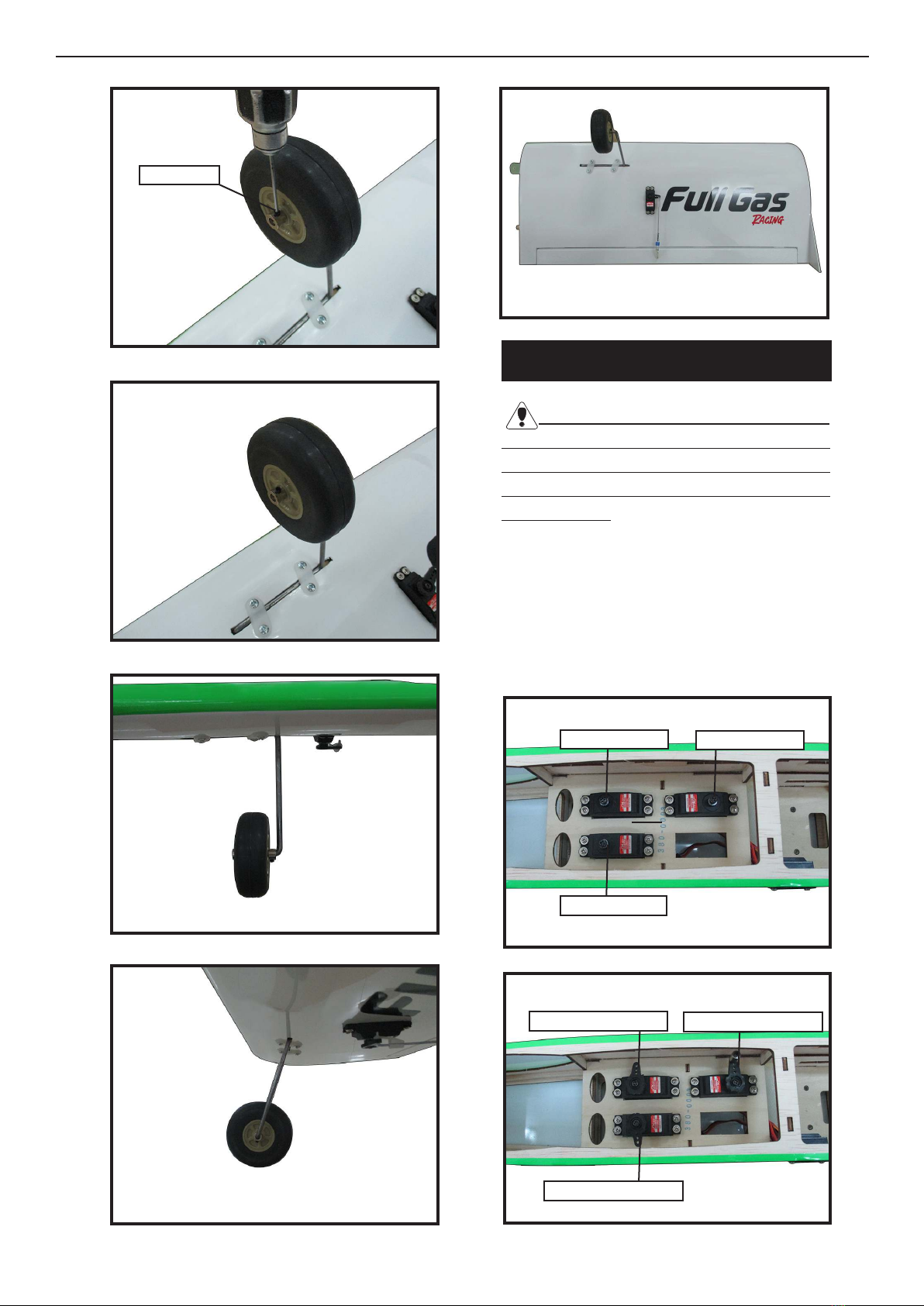
LANDING GEAR INSTALLATION
Using a modeling knife, remove the
covering from over the two main gear
mounting slots located in the bottom of
the wing.
2.
1.
Make a 90-degree bend at the mark and
cut o the excess wire leaving 8mm past
the bend.
4.
5.
Connect the linkage as shown and secure
the control wire with a snap keeper.
6.
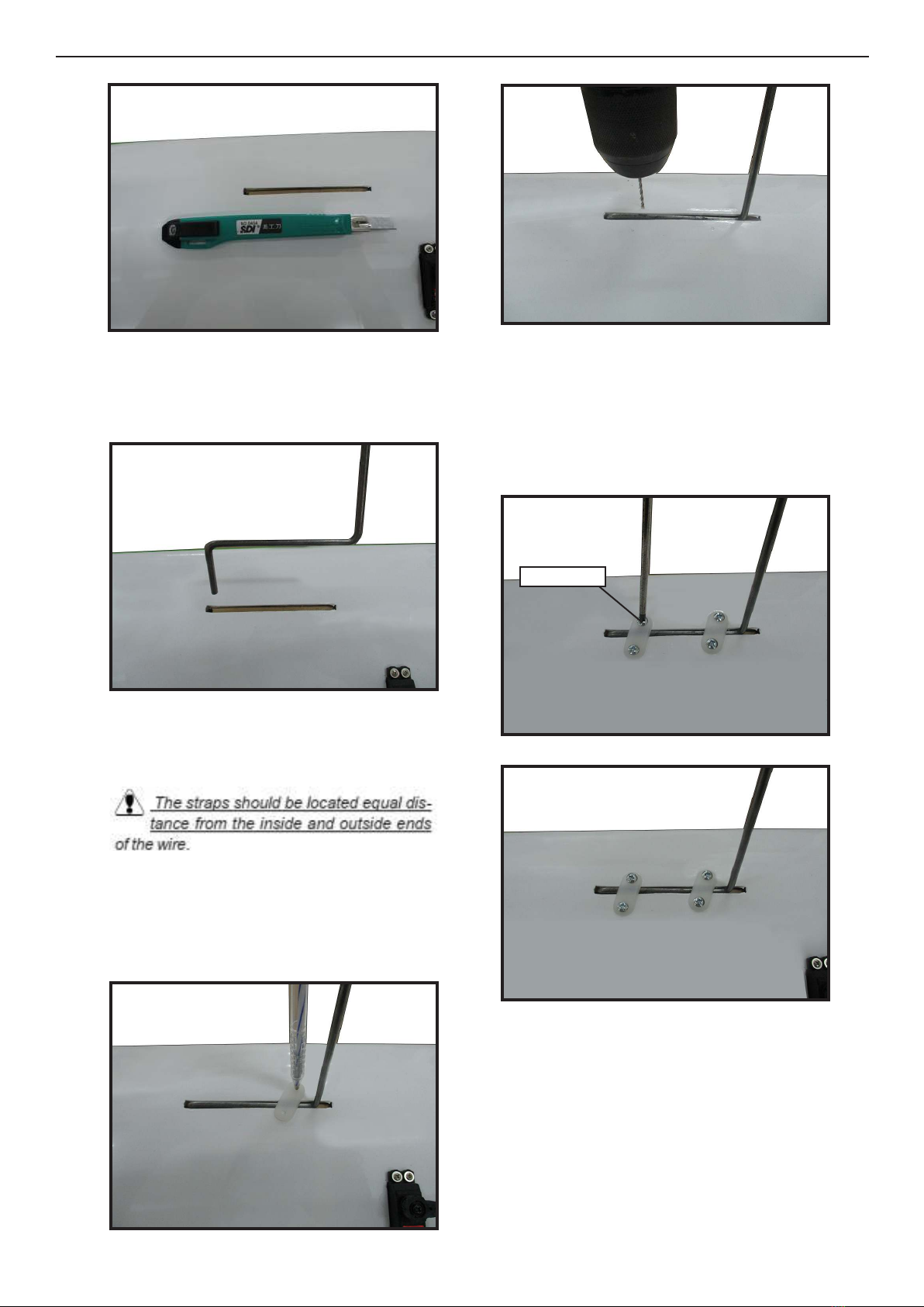
9
4.
5.
7.
8.
6.
Insert the 90º bend of one main gear
wire into the predrilled hole in one
mounting slot.
e landing gear wire is held in place
using two nylon landing gear straps and
four 3mm x 15mm wood screws.
Using the two landing gear straps as a
guide, mark the locations of the four
3mm x 15mm mounting screws onto the
wing surface.
Remove the two straps and the gear
wire. Drill four 3/32” pilot holes into the
wing for the wood screws.
Be careful do not to drill through the
top of the wing!
Reinstall the gear wire and install the
straps using the four 3mm x 15mm wood
screws. Tighten the screws completely to
secure the gear wire in place.
Slide one wheel collar with 3mm x 4mm
set hexagon snail onto each axle. Push
the wheel collars on as far as they will go
and tighten the set screws.
3.
M3x15mm

Magic Bird 46” EF1 Racer/Sport Plane ARF size .32-37 Instruction Manual.
10
Slide one 60mm diameter wheel onto
each axle and push them up against the
wheel collars. Slide the remaining wheel
collars with 3mm x 4mm set screws onto
the axles. Push them up against the wheels
and tighten the set screws. e wheels
should spin free and not bind in any way.
If they do bind, loosen the set screws in
the outer wheel collars and move the col-
lars out a small amount. Retighten the set
screws.
9.
10.
11.
12.
13.
14.
15.
M3x4mm
11
16.20.
17.
18.
19.
.
INSTALLING THE FUSELAGE SERVOS
.
Because the size of servos dier, you
may need to adjust the size of the precut
opening in the mount. e notch in the
sides of the mount allow the servo lead to
pass through.
Install the rubber grommets and brass
collets into all servos. Test t the servos
into the fuselage servo mounts.
Secure the servos with the screws
provided with your radio system.
1.
2.
Rudder servo
Elevator servo
rottle servo arm
Elevator servo arm
rottle servo
Rudder servo arm
M3x4mm

Magic Bird 46” EF1 Racer/Sport Plane ARF size .32-37 Instruction Manual.
12
Insert the switch into the pre-cut hole
in the fuselage.
3/32” Hole
1.
2.
INSTALLING THE ENGINE SWITCH
.
3.
Switch
.
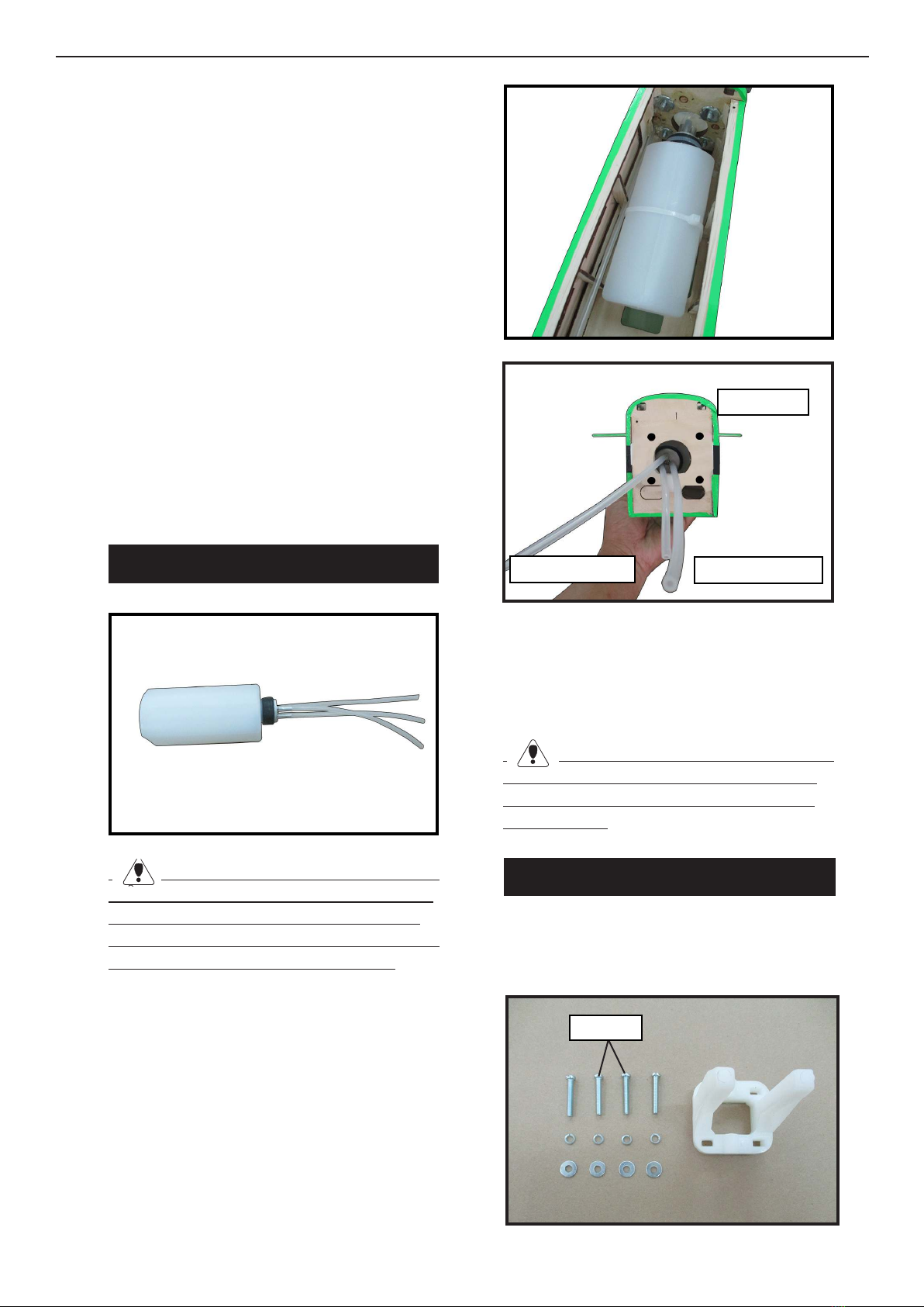
INSTALLING THE STOPPER
ASSEMBLY
Using a modeling knife, carefully cut
o the rear portion of one of the 3 nylon
tubes leaving 1/2” protruding from the
rear of the stopper. is will be the fuel
pick up tube.
Using a modeling knife, cut one length
of silicon fuel line. Connect one end of
the line to the weighted fuel pick up and
the other end to the nylon pick up tube.
1.
2.
Carefully bend the second nylon tube up at
a 45º angle. is tube is the vent tube.
3.Fuel pick up tube Vent tube
Fuel ll tube
Mininum servo spec.
Torque : 54 oz-in (3.9 kg-cm) @ 4.8V;
67 oz-in (4.8 kg-cm) @ 6.0V
13
Test t the stopper assembly into the tank.
It may be necessary to remove some of the
ashing around the tank opening using a
modeling knife. If ashing is present, make
sure none falls into the tank.
With the stopper assembly in place, the
weighted pick-up should rest away from the
rear of the tank and move freely inside the
tank. e top of the vent tube should rest just
below the top of the tank. It should not touch
the top of the tank.
When satised with the alignment of the
stopper assembly tighten the 3 x 20mm ma-
chine screw until the rubber stopper expands
and seals the tank opening. Do not over-
tighten the assembly as this could cause the
tank to split.
FUEL TANK INSTALLATION
You should mark which tube is the vent
and which is the fuel pickup when you attach
fuel tubing to the tubes in the stopper. Once
the tank is installed inside the fuselage, it may
be dicult to determine which is which.
1.
2.
Slide the fuel tank into the fuselage. Guide
the lines from the tank through the hole in
the ewall.
Use plywood template to hold in place the
fuel tank with C/A glue to secure the fuel-
tank inside the fuselage.
3.
Fuel pick up tube Fuel ll tube
Vent tube
Connect the lines from the tank to the
engine and muer. e vent line will
connect to the muer and the line from
the clunk tothe carburetor.
Blow through one of the lines to ensure
the fuel lines have not become kinked inside
the fuel tank compartment. Air should ow
through easily.
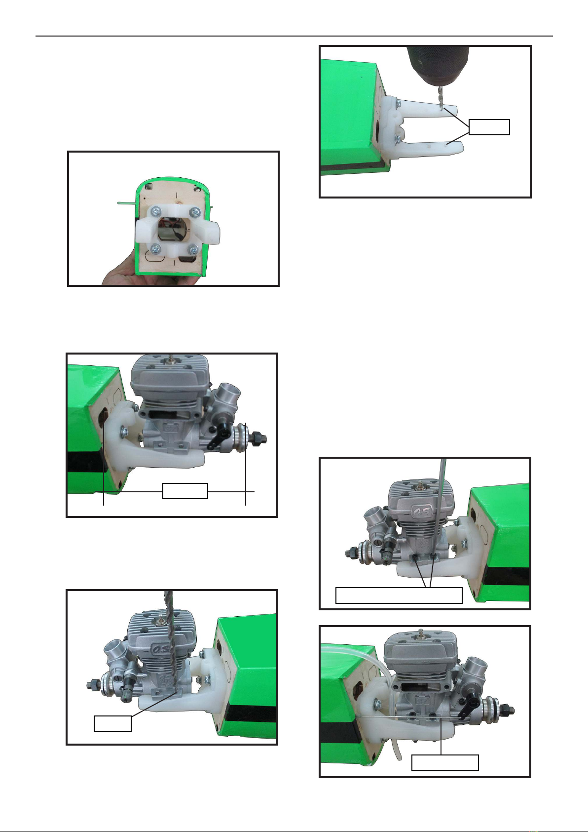
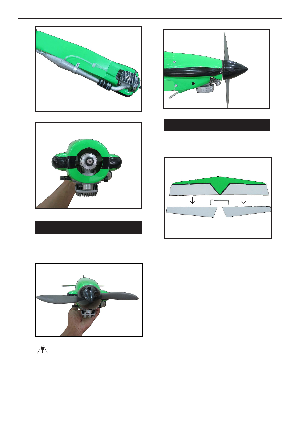
MOUNTING THE ENGINE
Locate the items necessary to install the
engine mount included with your model.
1.
4x25mm
Magic Bird 46” EF1 Racer/Sport Plane ARF size .32-37 Instruction Manual.
14
Use four 4x25mm head bolts and four
4mm washers to attach the engine mount
rails to the rewall. Tighten the screws
.Make sure to use threadlock on the
screws to help prevent them from vibrat-
ing loose.
Position the engine with the drive
washer (105mm) forward of the rewall
as shown
6.
4.
3.
5.
2.
Use a pin drill and 3mm drill bit to drill
a small indentation in the mount for the
engine mounting screw.
Use a drill to drill the four holes in the
engine mount rails.
On the e wall has the location for the
throttle pusshrod tube (pre-drill).
Slide the pushrod tube in the ewall and
guide it through the fuel tank mount. Use
medium C/A to glue the tube to the e-
wall and the fuel tank mount.
Connect the Z-bend in the 450mm
throttle pushrod to the outer hole of the
carburetor arm.
Slide the throttle pushrod wire into the
tube. Position the engine between the
mounts. Use four M3x25mm machine
screws to secure the engine to the mount
as shown.
7.
3mm
3mm
Pushrod wire
hexagon snail M3x25mm
105mm
15
8.
Reinstall the servo horn by sliding the
connector over the pushrod wire. Center
the throttle stick and trim and install the
servo horn perpendicular to the servo
center line.
9.
10.
Move the throttle stick to the closed po-
sition and move the carburetor to closed.
Use a 2.5mm hex wrench to tighten the
screw that secures the throttle pushrod
wire. Make sure to use threadlock on the
screw so it does not vibrate loose.
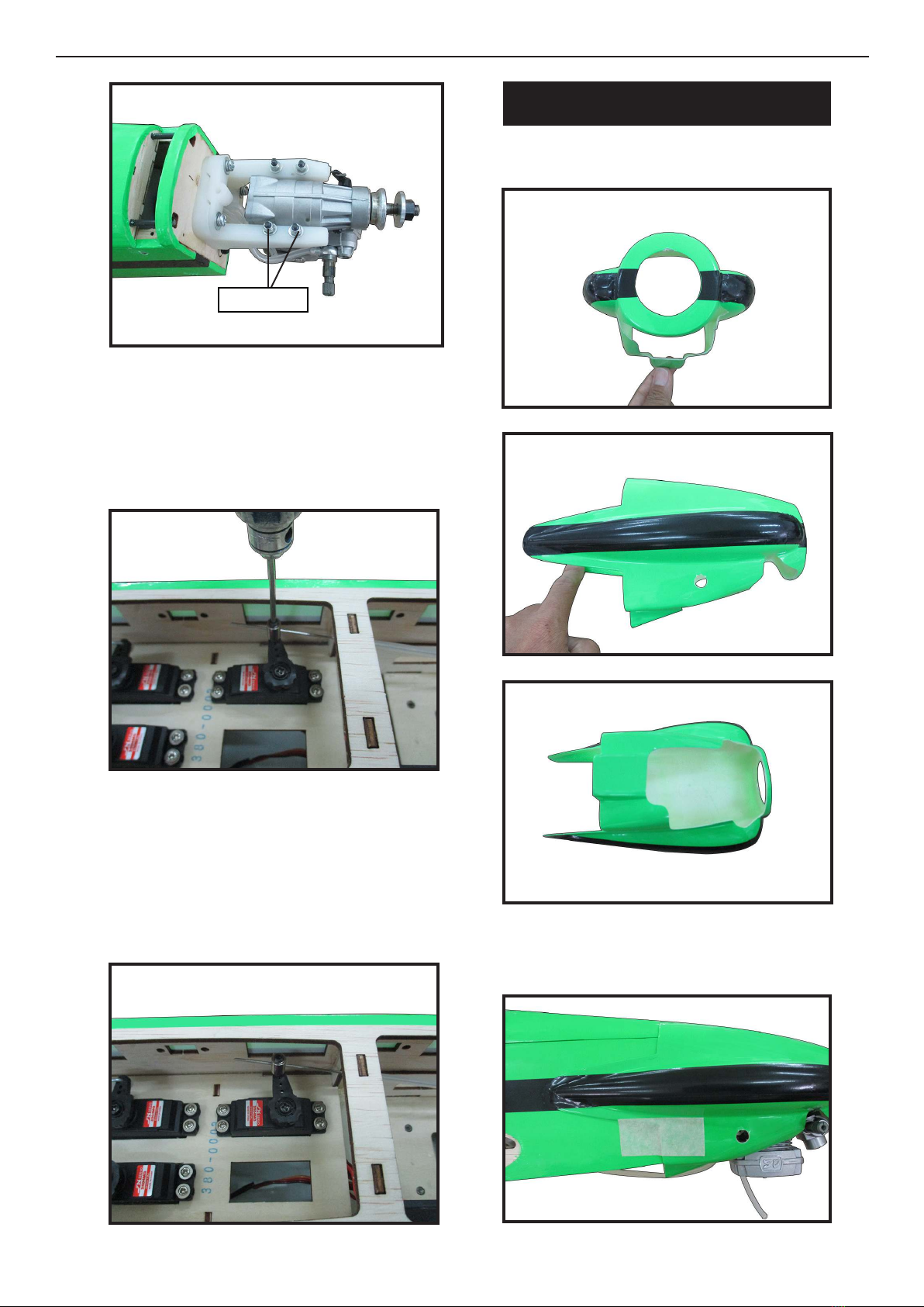
COWLING
Please see below pictures.
1.
2.
3.
4.
Tape the cowl to the fuselage using low-
tack tape.
M3 lock Nut

Magic Bird 46” EF1 Racer/Sport Plane ARF size .32-37 Instruction Manual.
16
9.
10.
11.
5.
Install the muer and muer exten-
sion onto the engine and make the cutout
in the cowl for muer clearance. Connect
the fuel and pressure lines to the carbu-
retor, muer and fuel ler valve. Secure
the cowl to fuselage using the M3x10mm
socket head screws.Putting a small length
of silicon fuel tube under the head of the
screw helps with vibration.
6.
8.
7.
M3x10mm
Use a drill and drill bit to drill the holes
for the cowl mounting screws. Make sure
the cowl position is correct before drill-
ing each hole.
17
12.
13.
1.
INSTALLING THE SPINNER
Install the spinner backplate, propeller
and spinner cone.
e propeller should not touch any
part of the spinner cone. If it does, use a
sharp modeling knife and carefully trim
away the spinner cone where the propel-
ler comes in contact with it.
2.
1.
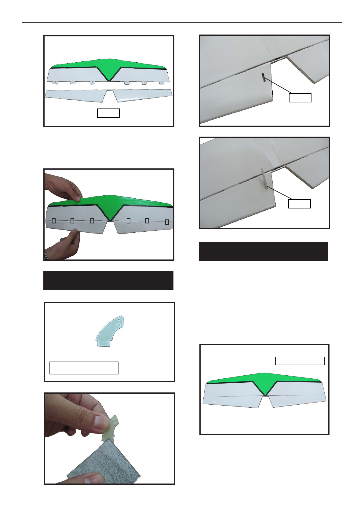
HINGING THE ELEVATORS
Locate the item for this section of the
manual.
Remove each hinge from the horizontal
stabilizer panel and elevator and place a
T-pin in the center of each hinge. Slide
each hinge into the elevator until the T-
pin is snug against the elevator. is will
help ensure an equal amount of hinge is
on either side of the hinge line when the
elevator is mounted to the horizontal sta-
bilizer panel.
Using epoxy, Install elevator joiner wire
into both elevator halves.
Carefully remove the elevator from
one of the horizontal stabilizer panels.
Note the position of the hinges.
Magic Bird 46” EF1 Racer/Sport Plane ARF size .32-37 Instruction Manual.
18
INSTALL ELEVATOR CONTROL HORN
Glue the elevator hinges in place using
the same techniques used to hing the ai-
lerons.
2.3.
4.
1.
1.
2.
3.
Epoxy
Fiberglass control horn
Epoxy
Epoxy
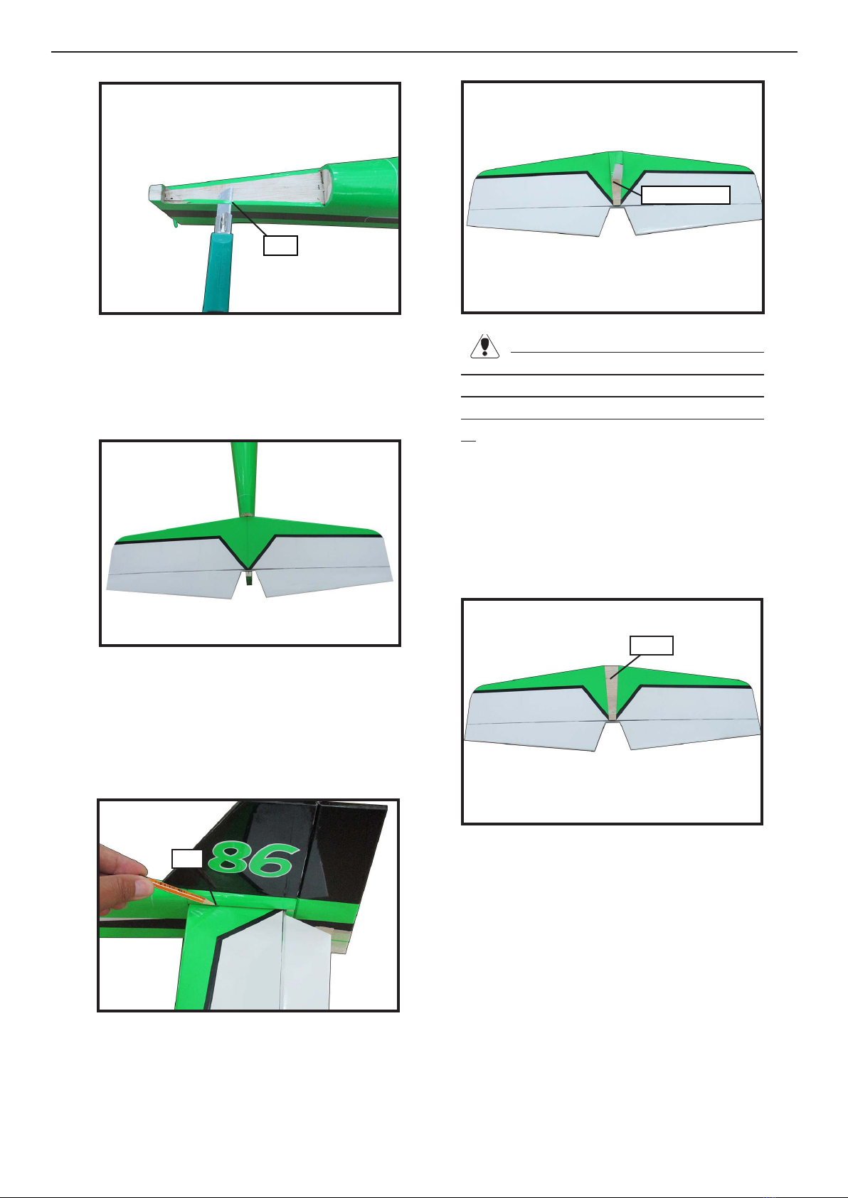
INSTALLING THE HORIZONTAL
STABILIZER
Using a ruler and a pen, locate the cen-
terline of the horizontal stabilizer, at the
trailing edge, and place a mark. Use a tri-
angle and extend this mark, from back to
front, across the top of the stabilizer. Also
extend this mark down the back of the
trailing edge of the stabilizer.
Draw center line
Using a modeling knife, carefully re-
move the covering at mounting slot of
horizontal stabilizer ( both side of fuse-
lage).
19
2.5.
6.
3.
4.
Slide the stabilizer into place in the
precut slot in the rear of the fuselage. e
stabilizer should be pushed rmly against
the front of the slot.
Cut
With the stabilizer held rmly in place,
use a pen and draw lines onto the stabi-
lizer where it and the fuselage sides meet.
Do this on both the right and le sides
and top and bottom of the stabilizer.
Remove the stabilizer. Using the lines
you just drew as a guide, carefully remove
the covering from between them using a
modeling knife.
Pen
When cutting through the covering
to remove it, cut with only enough pressure
to only cut through the covering itself. Cut-
ting into the balsa structure may weaken
it.
Trim and cut
Using a modeling knife, carefully re-
move the covering that overlaps the sta-
bilizer mounting platform sides in the
fuselage. Remove the covering from both
the top and the bottom of the platform
sides.
When you are sure that everything is
aligned correctly, mix up a generous
amount of 30 Minute Epoxy. Apply a thin
layer to the top and bottom of the stabi-
lizer mounting area and to the stabilizer
mounting platform sides in the fuselage.
Slide the stabilizer in place and realign.
Double check all of your measurements
once more before the epoxy cures. Hold
the stabilizer in place with T-pins or mask-
ing tape and remove any excess epoxy us-
ing a paper towel and rubbing alcohol.
Epoxy
Magic Bird 46” EF1 Racer/Sport Plane ARF size .32-37 Instruction Manual.
20
3.
4.
Rudder berglass control horn
Epoxy
.
Epoxy
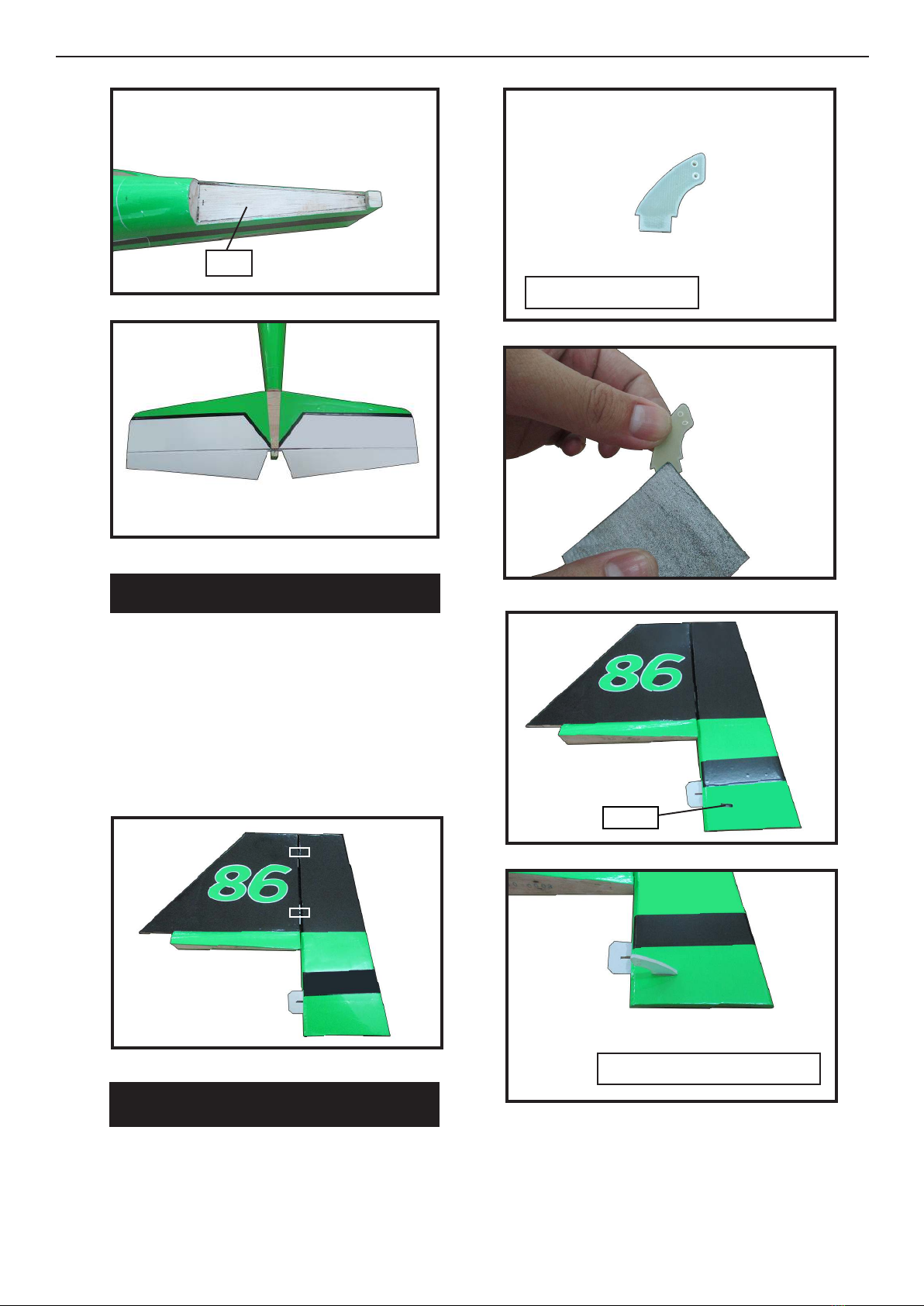
HINGING THE RUDDER
INSTALL RUDDER CONTROL HORN
Glue the top two rudder hinges in place
using the same techniques used to hinge
the ailerons.
e lower hinge will be glued when the
n/rudder assembly is attached to the fu-
selage.
Repeat steps to install the rudder control
horn as same as steps done for ailerons.
1.
1.
2.
Fiberglass control horn
7.
8.
Other Seagull Models Aircraft manuals


