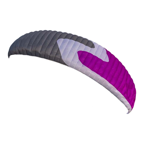
Triple Seven ROOK2 User manual

1

23
klj
USER MANUAL
Version 1.3, Date: 20.1.2016

45
Summary
1. ROOK2 3
II. Introduction 4
II.i. Welcome 4
II.ii. Triple Seven Mission 4
III. Manual 4
4. ROOK2 7
4.1. Designer’s thoughts 8
4.2. Who is this glider for? 9
4.3. Certication 9
5. Before ight 10
5.1. Elements, components 10
5.2. Assembly 10
5.3. Harness 11
5.4. Accelerator settings 11
5.5. Brakes’ adjustments 11
5.6. Weight range 12
5.7. Wing ination 12
5.8. Modications on the glider 12
5.9. Preight safety 12
6. Flying ROOK2 13
6.1. First Flight 13
6.2. Preight check equipment 13
6.3. Final preight check 14
6.4. Ination, control, take-off 14
6.5. Line knots or tangles 14
6.6. Normal ight, best glide 15
6.7. Minimum sink 15
6.8. Accelerated ight 15
6.9. Active ying 15
6.10. Flying in turbulence 16
6.11. Fast decent techniques 18
6.12. Winch launch 19
6.13. Aerobatics 19
6.14. Primary controls failure 19
6.15. Landing 19
7. Maintenance 20
7.1. General advice 20
7.2. Packing instructions 20
7.3. Storage 21
7.4. Cleaning 21
7.5. Repair 21
7.6. Checks and control 21
VIII. Packing ROOK2 22
9. Technical data 24
9.1. Technical data 26
9.2. Materials description 26
9.3. ROOK2 risers arrangement 27
9.4. Line plan ROOK2 28
9.5. Line lengths ROOK2 S 29
9.6. Line lenghts ROOK2 MS
30
9.7. Line lengths ROOK2 ML 31
9.8. Line lengths ROOK2 L 32
9.9. Certication specimens 33
X. Safety and responsibility 39
XI. Guarantee 40
XII.Registration information 41
XIII. Get involved 42
XIV. Contact 43
XV. Top 5 XC tips 44
Introduction
Welcome
Welcome to the Triple Seven Team! We are excited that you
have chosen to y the ROOK2, as we are condent that
this glider will be the next step in your piloting career. We
wish you exciting ying adventures!
Triple Seven Mission
Our company’s goal is to produce high quality products
and technologically innovative gliders of all types and
classes. We are striving to develop state of the art
paragliders, with the optimum compromise between
safety and performance, produced in Europe.
Your success is our inspiration; our goal is your success.
Manual
This document contains complete product information
and instructions to familiarize you with the main
characteristics of your new glider. It contains instructions
on how to use and maintain the wing, however, its
purpose is not to serve as learning material to pilot this
kind of wing. As such, this is not a ying manual. Flying
instructions can only be taught by ying schools and
specially certied instructors.
It is important that you take time to read this manual
carefully before the rst ight, as thorough knowledge of
your equipment enables you to y safely and to maximize
your full potential. If you borrow or give your glider to
another pilot, please pass this manual on with it.
If any use of Triple Seven equipment remains unclear
after having read this manual, please contact: your local
paragliding instructor, your Triple Seven importer or Triple
Seven. This product manual is subject to changes without
prior notice. Please check www.777gliders.com for the
latest information regarding our products. Introduction
Welcome

677
»Progressive handling, offering easy and precise
control characteristics
»Profile and trim speed optimized for good climbing
»Balanced wing tension, together with leading and
trailing edge reinforcements for greater stability and
good gliding performance throughout a wide speed
range
»Optimized geometry of the suspension lines and
materials for reduced drag and better gliding
performance
»Good pitch stability and easy to pilot
»Light weight and easy launch control
»EN-B, LTF-B certification
ROOK2 is a glider designed by theValic Brothers, made for local
soaring and cross country ying. The glider’s technical design is
based on experience and technology of competition wings, with
great emphasis on ease of ying and safety.
Who is this glider for?
This wing is a high performance EN-B, LTF-B certied glider intended
for intermediate to advanced pilots that want safety and high

89
9
8
Designer’s thoughts
Our design goal from the beginning was to upgrade the overall
good feeling of ROOK2 predecessor. We have managed to
gain big leap in performance which will remain manageable
for wide range of pilots in class B. Designing this wing was
great joy as we knew we are building something that will
feel safe and yet very performative in hands of many pilots.
Urban Valiè
performance in Who is this glider
for?
This wing is a high performance EN-B, LTF-B certied
glider intended for intermediate to advanced pilots
that want safety and high performance in this class.
Intermediate pilots may nd this glider great for the
progression of their piloting XC skills for years, whilst
experienced pilots will enjoy the comfort of safety and
performance on long cross country ights; even in
stronger air.
The pilot of this wing should be comfortable with the
basic active ying techniques of controlling a glider in
active air, naturally preventing pitch or roll movements. As
with any glider, we recommend constantly improving your
basic and advanced ying skills.
Certication
The ROOK2 has passed the European EN-B certication

10 11
Before ight
Elements, components
The ROOK2 is delivered together with a rucksack, inner bag,
compression strap, Triple Seven T-shirt and USB key with this manual.
Assembly
Before you rush to the rst take-off we recommend you take your
time to unpack and test your equipment on a training slope. In
this way you will have time and will not be distracted or rushed
to prepare your equipment, and you will be able to do your rst
pre-ight check properly.
The place should be at, free of obstacles, and with light wind.
This will enable you to nicely inate the wing and also familiarize
yourself with it while ground handling. Every glider has to be
checked by a Triple Seven dealer, however, as a pilot you want to
do a proper pre-ight check yourself.
Firstly, prepare and spread out the glider like you would normally
do. While you are spreading out and walking along the glider,
observe the fabric material for any abnormalities. When you are
done with the inspection of the canopy, grab the risers and spread
the lines, check if the risers and maillons (carabiners) are properly
closed. Identify and disentangle the A1, A2, B, C risers and the
lines including the brake lines. Connect the risers’ main attachment
points correctly to the harness, watch for any twists and make
sure that the main carabiners are properly closed.
Harness
The ROOK2 has passed EN-B certication testing using a GH -
ABS type harness. This certication allows the ROOK2 to be own
with most of the harnesses on the market, but keep in mind that
the change of a harness greatly inuences the feeling of the glider,
depending on the effectiveness of the harness weight shift. Check
with the harness manufacturer or with your instructor whether
your harness is of the proper type.
The length of the harness chest strap affects the distance between
the main carabiners and the wing’s handling as well as your stability
in the harness. Tightening the chest strap increases your stability,
but greatly increases the risk of twisting after a collapse. A tight
setting also increases the tendency to maintain a deep spiral. As a
rule of thumb, a more opened chest strap gives you more feedback
from the glider, which is good for your climbing efciency and
increases safety in a ying incident. But we strongly recommend
adjusting the length of the harness chest strap according to the
lengths used during certication. This setting varies according to
the harness size from 42cm to 50cm. Check the settings used
during testing under the certication specimen section.
We recommend that your rst ight with the ROOK2 is not also
with a new harness. Another rule of thumb is if you want to
experience the feeling of new equipment, change only one part
of equipment at a time.
Accelerator settings
The ROOK2 speed system increases the speed of the glider
by 14km/h with the accelerator at full travel, from trim speed at
38km/h to full speed at 52km/h.
Before attaching the accelerator system to the ROOK2 risers,
check that the speed system inside your harness is correctly
routed and that all pulleys are set correctly. Make sure there are
no knots or other obstacles that might make the accelerator get
stuck during usage.
The length of the speed bar lines should be adjusted on the ground
so that your legs are fully extended at the point of full accelerator
travel. While setting the speed line lengths make sure they are long
enough, so that the speed system does not accelerate the glider
by itself. If in doubt how to properly set the accelerator system,
please consult your instructor or Triple Seven dealer.
Brakes adjustments
The length of the brake lines has already been adjusted by the
manufacturer and is the same as used during the certication test
ights. The length is set and ne-tuned during the development of
the glider, therefore generally there should be no need to adjust
them. We recommend ying this setting for a while, and you can
still change it afterwards if you wish to do so. If you change the
length of the brakes, do it in a step by step process of 2 cm at
a time. Bear in mind that if you make the brake lines too short,
they might be applied unintentionally while the speed system is
being used.

12 13
Weight range
Each size of the ROOK2 is certied for its own weight range.
The above mentioned weight includes the weight of the pilot and
complete paragliding equipment, together with the glider, harness,
all accessories and optional ballast. Every glider changes its
characteristics by changing the take-off weight. We recommend
that you always y your glider in the specied weight range.
To measure your take-off weight, step on a scale with all your
equipment packed in the rucksack.
Lower half of the weight range
Flying the ROOK2, as any other glider, in the lower part of the
weight range, causes the agility of the glider to decrease, and
when ying through turbulence its tendency for collapses relatively
increases as compared to ying it in the upper wing loading range.
However, reactions after a collapse are less dynamic and sink rate
improves. Therefore, if you mainly y in weak conditions, you might
prefer this weight range.
Upper half of the weight range
Again, as with any other glider, ying the ROOK2 in the upper part
of the weight range increases the stability and agility of the glider.
Consequently, there is a slight increase in the glider’s speed and
also gliding performance, especially when ying against the wind.
If you normally y in stronger conditions and you prefer relatively
more dynamic ying characteristics, you should set the take-off
weight in the higher weight range. Reactions after a collapse may
be more dynamic in the upper half of the weight range.
Wing ination
Still being on the training slope and having prepared and checked
everything, inate your wing and play with it to get a feel of your
new glider while ground handling. By doing this you are making a
nal check of the canopy and lines, and that everything is in order.
You will nd that the ROOK2 inates very easily and smoothly
without excessive energy and with minimum pressure while moving
forwards. For ination and lifting the glider you may use only the
A1 risers. Do not pull on the risers just with your hands, instead
use your whole harness. Your hands should only accompany the
rising movement of the wing. When the wing is above you, apply
correct pressure on the brake lines and the glider will stay above
you.
Modications on the glider
Any modications of the lines or risers’ speed system cause the
loss of the certication, similarly to ying the wing outside the
weight range.
Preight safety
Before ying the ROOK2, you should obtain all practical and
theoretical training and the certication for ying this kind
of wing. Pilots should be physically and mentally t, using
complete paragliding equipment and ying only in conditions
suitable for their level of ying expertise.
Flying ROOK2
First Flight
Now that you have already familiarized yourself with your new glider
while ground handling on a training slope, you are ready for your
rst ight. For the rst ight it is recommend that you choose a
familiar ying area and to y your new glider in calm conditions.
Preight check equipment
Before every ight you need to do a pre-ight check and the
inspection of other equipment. Learn to do this, as it takes no
extra time.This procedure may vary, depending on the instructor,
pilot or equipment settings. Some pilots have their wing always
connected to the harness. However you should have a consistent
method of checking and preparing your equipment and doing the
nal pre-ight check.
1.
After the arrival on take-off, assess the suitability of ying
conditions.
2.
While walking around the canopy preparing and spreading
out the wing, you should at the same time inspect the canopy.
3.
After you check the lines and connect the risers to the harness,
grab the lines and slide them through your ngers as you walk
towards the canopy. In this way you double check that the lines
are not tangled, stuck or damaged.
Final preight check
1.
Strap into the harness. The leg straps should be the rst to be
connected on the take-off and the last ones to be released
after the ight. Make sure you are strapped in correctly and
wearing a helmet.
2.
Check the risers for a twist and that the carabiners are properly
closed. Check if the speed system is not affecting your risers
– accelerating unintentionally.
3.
Check the lines. The A riser lines should be on top, and all
lines untangled. Check if none of the lines are lying over or
below the canopy.
4.
Check the canopy. The glider should be spread out in the shape
of an arch and all cells open.
5.
Check the wind, take-off and airspace. The wind should be
favourable for take-off and the pilot’s level of expertise. Airspace
should be cleared, together with the take-off area.
Ination, control, take-off
The ROOK2 has easy take-off behaviour and does not require any
additional advice regarding the forward or reverse launch. Try to
divide and practice the take-off procedure in three steps.

14 15
1. Inating and raising the glider
2. Controlling the wing and wing check
3. Accelerating and take-off
It is always advisable to practice and improve proper launching
techniques as this reduces unnecessary additional stress before
the take-off.
Wind speeds up to 25 to 30km/h are considered strong and extra
care is required for the ight. If you are launching in strong winds
we recommend the reverse launch technique, with your brakes
in the right hands at all times. Launch the glider with a gentle pull
and then walk towards it if necessary to reduce the relative wind
force. When the glider is above you, gently control the wing and
take off.
Line knots or tangles
If you fail to observe a line knot or you nd yourself ying with a
knot before being able to prevent the unintentional, uncontrolled
take-off, try to stay away from the ground or other pilots by ying
away from the mountain, before taking any corrective action on
the wing. This means that you weight shift and/or counter brake
the opposite side of the wing and control the ying direction with
the least amount of force needed for the wing to y straight away
from the mountain.
Be careful not to apply too much brake or to y too slowly to
avoid a stall or spin. When you are at a safe distance away from
the mountain and you have gained relative height by ying away,
you may want to gently and briey pull the lines that are tangled
with the knot. If the knot is on the brake lines you might want to
gently and briey “pump” the appropriate brake line.
Please note that by pulling the lines, the knot may get stuck in
a worse position and the situation may escalate also to a stall
or spin. Therefore, if you estimate that you can control the wing
relatively safely and that the knot is not released by gently and
briey pulling the tangled lines, immediately y to the landing
zone and land safely.
Normal ight, best glide
Without any brakes applied and without using the accelerator,
the wing ies at the so called “trim speed“. In calm air this is
theoretically the best glide speed.The best speed glide depends
on the glider’s polar and air mass, vertical and horizontal speed.
We recommend reading more about the theory of the best glide
and McCready theory.
Minimum sink
If you apply brakes on both sides for about 15 to 20cm you will slow
the glider to the theoretical minimum sink speed. But we do not
recommend using this speed even for thermalling, as you achieve
much better climbing and control by letting the glider y with its
“trim speed” and natural energy. With a proper take-off weight
you will nd that the glider has great climb, reactions and agility.
Accelerated ight
After you get comfortable ying the ROOK2, you can start
practicing using the speed system, which will provide better
performance while gliding against the wind and through a sinking
air mass. The ROOK2 was designed to be stable through its entire
speed range, but this requires the use of active ying techniques.
Note that any glider becomes less stable while ying accelerated
and that the risk of a collapse is higher in accelerated ight.
Additionally, the reaction of the glider to a collapse in accelerated
ight is more radical in comparison to the one which occurs at
trim speed.
We recommend that you avoid accelerated ight near the ground
and to be very careful using the accelerator in turbulent conditions.
Use a soft speed bar, which enables you to accelerate the glider
by using only one leg. To control the direction use weight shift. To
control the pitch change the amount of the speed bar. Do not use
or pull the brakes while using the speed bar. Use the speed bar
progressively when accelerating and instantly release when you
feel a slight loss of tension, pressure or even a collapse. If you
encounter a collapse while using the accelerator, release the speed
bar immediately before taking any other corrective action. Always
keep more distance from the ground when using the speed bar.
Active ying
This is a basic ying technique for any intermediate and advanced
pilot. It implies permanent control and the correction of pitch and
roll movements together with the prevention of any deations or
collapses. In a nutshell this means ying straight through active
or turbulent air, so that the pilot keeps the glider above his or
her head at all times, compensating and correcting any unwanted
movements of the wing.
Few examples:
• While entering a strong thermal, the wing will stay a little bit
behind relative to the pilot. The pilot should let the brake up
allowing the wing to y faster and to catch up.
•
If the wing surges in front of the pilot, the pilot should counter
brake until the surge is controlled and then release the glider
to let it y normally.
•
If the pilot feels a loss of tension on the wing or a loss of
pressure on the brakes on one side of the wing, he should
smoothly apply the brake on the side with loss of pressure and/
or weight shift to the opposite side until the pressure returns.
After that, again release the brake and/or weight shift to the
neutral position and let the glider y normally.
The key in all cases is to avoid an over-correction and not to
maintain any correction longer than necessary. After each action
let the glider y normally again. To re-establish its required ying
speed.You can train or get a feeling for most of these movements
safely on the ground while ground handling your glider. Good
coordination of your movements and coordination with the wing
on the ground will enable you a quick progression when actively
ying in the air. The next step is to attend SIV courses where you
should also get a better understanding of the full brake range and
the glider’s speeds.

16 17
Flying in turbulence
Wing deations can occur in a strong turbulence. The ROOK2 is
designed and tested to recover without pilot’s input in almost all
situations by simply releasing the brakes and letting the glider
y. To train and understand all the manoeuvres described, attend
SIV courses.
Cascade of events
Many reserve deployments are the result of a cascade of
over-corrections by the pilot. Over-corrections are usually not
problematic because of the input itself or its intensity; but due to
the length of time the pilot continues to over-handle. After every
input you have to allow the wing to re-establish its normal ying
speed. Note that over-corrections are often worse than no input
at all.
Asymmetric deflations
Strong turbulence may cause the wing to collapse asymmetrically.
Before this occurs the brake lines and the feeling of the harness
will transmit a loss of pressure to the pilot. This feedback is used
in active piloting to prevent a collapse. If the collapse does occur,
the ROOK2 will easily re-inate without the pilot’s reaction, but
the wing will turn towards the collapsed side.
To prevent this from happening turn and actively recover the
asymmetric collapse by weight shifting and applying appropriate
brake input on the side that is still ying. Be careful not to over-
brake your wing’s ying side. This is enough to maintain your
course and give the glider enough time to recover the collapsed
side by itself. To actively reopen the collapsed side after course
stabilization, pull the brake line on the collapsed side rmly and
release it. You can do this several times with a smooth pumping
motion. After the recovery, release the brake lines for your glider to
regain its trim speed. You must be aware of the fact that asymmetric
collapses are much more radical when ying accelerated. This is
due to the difference in weight and the inertia of the canopy and
the pilot hanging below.
Symmetric deflations
Symmetric or frontal deations normally reopen immediately by
themselves without pilot’s input. The glider will then regain its
airspeed accompanied by a small surge forwards. To actively
control this event, apply both brakes slightly when the collapse
occurs and then instantly release the brakes to let the glider y.
Be prepared to compensate for the glider’s slight surge forward
while returning to normal ying.
Wing tangle, cravat
A cravat is very unlikely to happen with the ROOK2, but it may
occur after a severe deation or in a cascading situation, when
the wing tip gets caught in the glider’s lines. A pilot should be
familiar with the procedure of handling this situation with any
glider. Familiarize yourself with the stabilizer’s main line (“stabilo”
line) already on the ground. If a cravat occurs, the rst thing to
do is to try to keep the glider ying on a straight course. Do this
by weight shifting and counter braking the untangled side. After
that, grab the stabilizer’s main line on the tangled side and pull it
down until it becomes tight again. At this point the cravat normally
releases itself.
Possible solutions of the cravat situations (consult your SIV
instructor):
• Pulling the wing tip “stabilo” line
•
Using a full stall, but it is essential to be very familiar with this
manoeuvre. You also want to have a lot of relative height.
• If you are in a situation where you have a cravat and you are
low in rotation or even with twisted risers, then the only solution
is the reserve parachute.
Negative spin
In normal ight you are far from negative spin. But, certain
circumstances may lead to it. Should this occur, just release the
brake lines progressively and let the wing regain its ying speed.
Be prepared for the glider to surge forward, compensating the
surge with brake input if necessary.
Full stall
A full stall does not occur unintentionally on its own – it happens
if you pull both brakes for 100% and hold them. The wing then
performs a so called full stall. Releasing the brakes improperly
may lead to massive surge of the glider with danger of falling into
the canopy. This is a complex manoeuvre and as such outside the
scope of this manual.You should practice and learn this manoeuvre
only on a SIV course under professional supervision.
Deep stall
Generally when in deep stall, the wing has no forward motion and
at the same time high sink speed. When in deep stall the wing is
almost fully inated. With the ROOK2 it is very unlikely to get into
this situation unintentionally. This could possibly happen if you
are ying at a very low speed in turbulent conditions. Also the
porosity of the material and line stretch on a very old glider can
increase the possibility of the deep stall tendency. If you trained
this manoeuvre on a SIV course you would realize that it is very
hard to keep the ROOK2 in deep stall. If you apply the brakes a
little bit too much you enter the full stall. If you release the brakes
just a little bit too much the wing returns to normal ight. If you
want to practice the deep stall on SIV courses, you need to master
the full stall rst.
Fast decent techniques
Fast descent techniques should be well familiar to any pilot as they
are important resources to be used in certain situations. These
manoeuvres should be learned at your ying school as a part of
paragliding pilot training. Nevertheless, we recommend practicing
these manoeuvres on SIV courses under professional supervision.
Big ears
This is a safe method to moderately loose altitude while still
maintaining forward speed. To do big ears, release any brake line
loops around your wrist, set your leg on the speed bar, but do not
push it. Now pull the outer A lines (the A2 risers in the drawing)
on both sides. As long as you keep the A2 risers pulled, the wing
tips stay folded and the sink speed increases. To regain normal
ight, release the A2 risers, and if necessary apply the brakes with
short impulse movements. Release big ears at least 100 meters
above the ground. While using big ears, the wing speed decreases,
which is why we also recommend using the accelerator half way
in combination with big ears to maintain enough horizontal speed
and to also additionally increase vertical speed. Be careful not to
pull the brakes while making the ears! Steering is done by weight
shift only. Always do the big ears rst and then accelerate; not
the other way around as you will risk getting a frontal collapse.

18 19
B line stall
While in the B-stall the glider has no horizontal speed and the
sink rate increases to about -8m/s. To enter the B-stall reach
for the B risers just below the maillons and pull both B line
risers symmetrically for about 20 cm. To exit the manoeuvre,
simultaneously release both risers quickly. On exit the ROOK2
2gently dives without deep stall tendencies.
Spiral dive
The spiral dive is the most demanding of all three manoeuvres
(Big ears, B-stall, Spiral) and should only be trained gradually and
always at high altitude. The spiral dive should be practiced and
learned on a SIV course under professional supervision.
To enter the spiral, weight shift to the desired side and gradually
apply the brake on the same side. Then let the wing accelerate
for two turns and you will enter the spiral dive. While in the spiral,
you can control your descent rate and bank angle by applying
more or less inner brake. Depending on how steep the spiral is
you may need to use also outer brake.
To exit the spiral dive we recommend that the pilot is in the neutral
weight shift position. If you release the inner brake, the wing exits
the spiral dive by itself. The ROOK2 has no tendency of a stable
spiral but you should be aware of the procedure for exiting a
stable spiral.
To exit a stable spiral dive, weight shift to the opposite side of
the turn and apply the outer brake until feeling the deceleration of
the wing rotation. Then release the outer brake and let the glider
decelerate for the next couple of turns. To avoid a big pendulum
movement after exiting the spiral, apply a short brake input on
the inner side before the glider exits the spiral.
Warnings (Spiral dive):
•
There is a possibility of losing consciousness while in the
spiral dive. Never make a spiral with more than 16-18m/s
sinking speed.
•
In fast spirals it may be necessary to apply the outer brake to
begin exiting the spiral dive.
• If practicing the spiral dive low, a pilot may not have enough
altitude or time to safely exit this manoeuvre.
Winch launch
The ROOK2 is easy to launch using a winch and has no special
characteristics considering this kind of launching. To practice this
launching technique special training is needed and you have to
be aware of the procedures and dangers, which are specic for
winching. We do not recommend using any special towing device
which accelerates the glider during the winch launch.
Aerobatics
The ROOK2 was not designed for aerobatics, therefore, these may
not be performed on this glider. In addition to this, any extreme
manoeuvres place unnecessary stress on the glider and shorten
its lifespan.
Primary controls failure
If for any reason you cannot use the brake lines, you have to pilot
the wing to the landing place by using weight shift. Weight shift
should be enough to safely land the glider.You can also use the C
risers to control and steer the wing. Be careful not to over-handle
the glider by using the C riser technique when steering. By pulling
the C risers too strong you can cause a stall or a negative spin.
Land your glider at trim speed without using the C risers, to avoid
over-handling the glider low above ground. We recommend using
weight shift.
Landing
Similarly to the take-off, the ROOK2’s landing characteristics are
easy. In turbulent conditions it is advisable to apply about 15%
of the brakes, to increase stability and the feeling of the glider.
Before landing, adopt the standing position as this is the most
effective and the safest way to compensate the touch down with
your legs. Again we recommend training the landing manoeuvre,
as it might be useful to be able to land in small places, especially
in an unknown cross country terrain. Learn to evaluate the wind
direction by observing the signs on the ground and also your drift
while making turns. This proves to be useful for cross country,
when landing outside of your usual landing eld. Another advice
we suggest taking into account in stronger winds is to go higher
for the landing elds and thus assuring you reach them. Likewise,
always look for possible alternatives downwind.

20 21
Maintenance
General advice
Careful maintenance of your glider and the following simple
guidelines will ensure a much longer airworthiness and performance
of your wing:
•
Pack your glider after you land and do not unnecessarily
expose it to UV radiation by leaving it on the landing site
unpacked.The sun UV radiation degrades the cloth and lines
material.
•
Fold your glider like recommended under the section of packing
instructions.
• If the glider is damp or wet when you pack it, partially unfold
it at home to allow it to dry. Do not dry it in direct sunlight.
•
Avoid exposing the glider to violent shocks, such as the leading
edge hitting the ground.
•
Avoid dragging the glider on the ground or through rocky
terrain as you might damage the lines or canopy.
• Avoid stepping on the lines or canopy, especially when they
are lying on a hard surface.
•
Avoid exposing the glider to salt water, as it damages the lines
and the canopy material (wash with fresh water).
• Avoid bending your lines, especially in a small radius.
•
Avoid opening your glider in strong winds without rst
untangling the lines.
•
In general, avoid exposing your glider to very hot or humid
environments, UV radiation or chemicals.
Packing instructions
It is important to correctly pack your glider as this prolongs its
lifespan. We recommend that you fold the glider like a harmonica,
neatly aligning the proles with the leading edge reinforcements
side by side. The wing should then be folded in three parts or two
folds. The wing should be packed as loosely as possible. While
packing be careful not to trap any grasshoppers inside your canopy
as they will tear the canopy cloth. This technique will make your
glider last longer and ensure its best performance.
Storage
Correctly packed, store your glider in a dry place at room
temperature. The glider should not be stored damp, wet, sandy,
salty or with objects inside the cells of the glider. Keep your
equipment away from any chemicals.
Cleaning
If necessary always clean your glider with fresh water and a cloth
only, without using any cleaning chemicals. This includes also the
lines and canopy. More importantly, always remove any stones or
sand from the canopy as they will gradually damage the material
and reduce the glider’s lifespan.
Repair
To repair small damages (less than 5cm) on the canopy cloth, you
can use the rip stop tape. Greater damages, including stitches and
lines must be repaired by a specialized repair shop. Damaged lines
should be replaced by a Triple Seven dealer. When replacing a line it
should always be compared with the counterpart for adjusting the
appropriate length. After the line was repaired, the wing should be
inated before ying, to ensure that everything was done correctly.
Major repairs, such as replacing panels, should only be carried
out by aTriple Seven distributor or Triple Seven. If you are unsure
about the damage or in any doubt please contact Triple Seven.
Checks and control
To ensure the wing’s airworthiness the ROOK2 has to be
periodically serviced and checked to guarantee that the glider
continues to full the EN certication results and to extend your
glider’s lifespan. We recommend a line check and trim inspection
every 100 hours or 12 months depending what happens rst. After
that, the glider needs to be fully checked after 150 hours or 24
months of usage, whichever comes earlier. This inspection includes
checking the suspension lines, line geometry, riser geometry and
the permeability of the canopy material. A certied inspector can
then dene the check interval depending on the glider’s condition.
Please note that the condition of the glider can vary considerably
depending on the type of usage and environment. Salty coastal
air or dunes will considerably affect your wing’s material. For more
information please visit our website.

22 232222
Packing ROOK2
23
1. FOLD THE GLIDER LIKE HARMONICA
2. ALIGN THE CELLS
3. FOLD LEADING EDGE BACK TOWARD TRAILING EDGE AND ALIGN THE CELS
4. FOLD THE GLIDER IN THREE PARTS
5. FINISHED

24 25
Technical data
1. Suspension lines
2. Risers
3. Main lines
4. Middle cascades
5. Upper cascades
6. Brake lines
1. Canopy
2. Bottom surface
3. Top surface
4. Leading edge
5. Trailing edge
6. Intake cell openings
1.
2.
3.
6.
4.
5.
3.
2.
6.
5.
4.
1.

26 27
Technical data Materials description ROOK2 risers arrangement
SIZE ROOK2 S ROOK2 MS ROOK2 ML ROOK2 L
CELLS NUMBER 57 57 57 57
FL AT AREA m223.7 26 28.3 30.6
SPAN m 11.6 12.0 12.6 13.1
ASPECT RATIO 5.6 5.6 5.6 5.6
PROJECTED AREA m220 21.9 23.8 25.8
SPAN 9.1 9.4 9.9 10.3
ASPECT RATIO 4.1 4.1 4.1 4.1
RISERS A B C
ROOK2 S LENGTHS (mm) 530 530 530 STANDARD
ROOK2 S LENGTHS (mm) 380 422 530 ACCELER-
ATED
S-Distance between pulleys: 150
ROOK2 MS LENGTHS (mm) 575 575 575 STANDARD
ROOK2 MS LENGTHS (mm) 380 455 575 ACCELER-
ATED
MS-Distance between pulleys: 180
ROOK2 ML LENGTHS (mm) 580 580 580 STANDARD
ROOK2 ML LENGTHS (mm) 390 443 580 ACCELER-
ATED
ML-Distance between pulleys: 190
ROOK2 L LENGHTS (mm) 580 580 580 STANDARD
ROOK2 L LENGHTS (mm) 380 435 580 ACCELER-
ATED
L-Distance between pulleys: 200
TRIMS ROOK2 S ROOK2 MS ROOK2 ML ROOK2 L
NO NO NO NO
IN FLIGHT WEIGHT MINIMUM kg 65 80 95 110
MAXIMUM kg 85 100 115 130
GLIDER WEIGHT kg 5.2 5.6 6.1 6.6
CERTIFICATION EN/LTF B B B
CANOPY FABRIC CODE
Upper surface Dominico N30 DMF
Bottom surface Dominico N20 DMF
Proles Dominico N30 DMF
Nose reinforcement Plastic wire 2.4mm 2.7mm 2.5mm
SUSPENSION LINES FABRIC CODE
Upper cascades Edelrid A-8000-U-070-000
Upper cascades Edelrid A-8000-U-090-000
Upper cascades Edelrid A-8000-U-050-000
Upper cascades ML, L Edelrid 8000U-200
Middle 1 cascaded ML, L Edelrid 8000U-200
Middle1 cascades Edelrid A-8000-U-090-000
Middle1 cascades Edelrid A-8000-U-070-000
Middle1 cascades Elderid A-8000-U-050-000
Middle1 cascades Liros PPSL 191
Middle 2 cascades Elderid A-8000-U-090-000
Main ML, L Liros PPSL 200
Main Liros PPSL 191
Main stabilo A-8000-U-070-000
Brake upper Liros DC-40
Brake middle 1 Elderid A-8000-U-050-000
Brake middle 2 Edelrid A-8000-U-070-000
Brake main
Liros PPSL 160 connected A8000-
U-120
RISERS FABRIC CODE
Material Liros 13 mm black nylon webbing
Pulleys 4x Harken PA18
1. A1 riser
2. A2 riser, (Ears)
3. B riser, (B-Stall)
4. C riser
5. Maillons
6. Main attachment point
7. Speed bar attachment point
8. Speed bar pulleys (200mm)
9. Brake handle
10. Brake line pulley
11. Main brake line
12. Clip for brake handle
13.
ROOK2 has no trimmers or any
other adjustable or removable
device
4.
3.
2.
10.
6.
7.
12.
1.
5.
9.
11.
8.

28 29
28
Line lengths ROOK2 L
Line plan ROOK2 Lines Length (mm) LINE CHECK
First gallery a1 7056 c1 7242
Lines A mm Lines B mm Lines C mm Lines D mm BR lines mm a2 7032 c2 7152
a1 2084 b1 1620 c1 447 d1 843 br1 1020 a3 7053 c3 7103
a2 2059 b2 1593 c2 357 d2 855 br2 684 a4 7002 c4 7123
a3 480 b3 477 c3 352 d3 728 br3 849 a5 6984 c5 7127
a4 430 b4 426 c4 371 d4 680 br4 805 a6 7004 c6 7060
a5 426 b5 435 c5 428 d5 443 br5 74 5 a7 6923 c7 7023
a6 445 b6 452 c6 361 d6 274 br6 627 a8 6843 c8 7051
a7 859 b7 867 c7 365 br7 596 a9 6743 c9 6945
a8 779 b8 786 c8 393 br8 656 a10 6738 c10 6840
a9 440 b9 454 c9 384 br9 612 a11 6486 c 11 6749
a10 435 b10 455 c10 243 br10 524 a12 6411 c12 6755
a11 341 b11 317 c 11 398 br11 559 a13 6241 c 13 6395
a12 267 b12 252 c12 403 br12 592 b1 7006 c14 6355
a13 648 b13 659 c13 288 b2 6979 d1 7273
c14 248 b3 6987 d2 7231
b4 6936 d3 7153
b5 6914 d4 7105
Second gallery b6 6931 d5 7004
Lines A mm Lines B mm Lines C mm Lines C mm BR lines mm b7 6854 d6 6874
A1 4989 b1 5392 2c1 369 1C1 824 1BR1 1332 b8 6773 br1 8256
1A1 1763 1B1 1748 2c2 379 1C2 771 1BR2 931 b9 6688 br2 7920
1A2 1749 1B2 1717 2c3 277 1C3 1301 1BR3 958 b10 6689 br3 7684
1A3 1439 1B3 1378 2c4 236 1C4 1300 1BR4 911 b11 6434 br4 7640
1A4 1678 1B4 1626 2c5 491 1C5 1248 1BR5 76 7 b12 6369 br5 7468
1s1 1244 s2 12 17 2c6 527 1BR6 684 b13 6252 br6 7350
1s2 692 1c6 1526 br7 7272
1s3 1207 br8 7332
Main Lines br9 7207
Lines A mm Lines B mm Lines C mm BR lines mm br10 7122
A2 4829 B2 4771 C1 5624 BRI 2677 br11 7071
A3 4644 B2 4618 C2 5144 BRII 2538 br12 7104
Smain 4909 C3 4844 BRIII 2601
Brmain1 1674
br main 1493

30 31
Line lengths ROOK2 ML Line lengths ROOK2 MS
Lines Length (mm) LINE CHECK
First gallery a1 6490 c1 6650
Lines A mm Lines B mm Lines C mm Lines D mm BR lines mm a2 6465 c2 6571
a1 1505 b1 1496 c1 4 13 d1 786 br1 936 a3 6470 c3 6523
a2 1480 b2 1468 c2 329 d2 795 br2 626 a4 6423 c4 6540
a3 443 b3 440 c3 325 d3 678 br3 781 a5 6405 c5 6541
a4 396 b4 393 c4 342 d4 634 br4 74 6 a6 6422 c6 6478
a5 394 b5 402 c5 395 d5 415 br5 688 a7 6349 c7 6443
a6 411 b6 417 c6 333 d6 261 br6 578 a8 6275 c8 6468
a7 743 b7 749 c7 338 br7 551 a9 6184 c9 6372
a8 669 b8 674 c8 363 br8 605 a10 6181 c10 6275
a9 356 b9 368 c9 354 br9 566 a11 5932 c 11 6191
a10 353 b10 371 c10 224 br10 486 a 12 5863 c12 6199
a11 315 b11 293 c11 318 br11 516 a13 5709 c13 5861
a12 246 b12 233 c12 325 br12 546 b1 6443 c14 5824
a13 594 b13 610 c13 266 b2 6414 d1 6683
c14 229 b3 6418 d2 6642
b4 6371 d3 6566
b5 6348 d4 6518
Second gallery b6 6363 d5 6431
Lines A mm Lines B mm Lines C mm Lines C mm BR lines mm b7 6294 d6 6310
A1 4984 b1 4937 2c1 342 1C1 761 1BR1 1232 b8 6219 br1 7572
1A1 1629 1B1 1615 2c2 350 1C2 710 1BR2 857 b9 6141 br2 7270
1A2 1613 1B2 1582 2c3 256 1C3 1202 1BR3 884 b10 6152 br3 7050
1A3 1328 1B3 1272 2c4 2 17 1C4 1200 1BR4 839 b 11 5894 br4 70 01
1A4 1548 1B4 150 0 2c5 403 1C5 115 2 1BR5 709 b12 5832 br5 6844
1s1 114 0 s2 1123 2c6 435 1BR6 631 b13 5832 br6 6716
1s2 639 1c6 14 13 br7 6662
1s3 1119 br8 6716
Main Lines br9 6607
Lines A mm Lines B mm Lines C mm BR lines mm br10 6539
A2 4398 B2 4357 C1 5153 BRI 2479 br11 6475
A3 4278 B2 4266 C2 4702 BRII 2239 br12 6509
Smain 4480 C3 4477 BRIII 2399
Brmain1 1405
br main 1488
Lines Length (mm) LINE CHECK
First gallery a1 6775 c1 6938
Lines A mm Lines B mm Lines C mm Lines D mm BR lines mm a2 6751 c2 6851
a1 1799 b1 1559 c1 430 d1 815 br1 958 a3 6765 c3 6799
a2 1775 b2 1532 c2 343 d2 825 br2 637 a4 6716 c4 6819
a3 462 b3 459 c3 339 d3 703 br3 8 19 a5 6698 c5 6821
a4 413 b4 410 c4 357 d4 657 br4 734 a6 6716 c6 6757
a5 410 b5 419 c5 412 d5 428 br5 764 a7 6639 c7 6722
a6 428 b6 435 c6 347 d6 268 br6 605 a8 6562 c8 6747
a7 802 b7 809 c7 352 br7 573 a9 6466 c9 6647
a8 725 b8 731 c8 378 br8 570 a10 6462 c10 6546
a9 399 b9 412 c9 369 br9 588 a 11 6216 c 11 6460
a10 395 b10 414 c10 234 br10 519 a12 6144 c12 6466
a11 328 b11 305 c11 359 br11 538 a13 5981 c13 6137
a12 257 b12 242 c12 365 br12 567 b1 6720 c14 6088
a13 626 b13 635 c13 277 b2 6692 d1 6979
c14 239 b3 6698 d2 6937
b4 6649 d3 6861
b5 6627 d4 6814
Second gallery b6 6642 d5 6717
Lines A mm Lines B mm Lines C mm Lines C mm BR lines mm b7 6570 d6 6591
A1 4982 b1 5167 2c1 356 1C1 794 1BR1 1294 b8 6492 br1 7939
1A1 1697 1B1 1683 2c2 365 1C2 741 1BR2 896 b9 6410 br2 7616
1A2 1682 1B2 1651 2c3 266 1C3 1252 1BR3 924 b10 6412 br3 7391
1A3 1385 1B3 1326 2c4 227 1C4 1251 1BR4 878 b 11 6165 br4 7312
1A4 1615 1B4 1564 2c5 448 1C5 1201 1BR5 722 b12 6102 br5 7196
1s1 119 9 s2 117 1 2c6 482 1BR6 659 b13 5989 br6 7035
1s2 666 1c6 1469 br7 6960
1s3 115 9 br8 6957
Main Lines br9 6858
Lines A mm Lines B mm Lines C mm BR lines mm br10 6788
A2 4614 B2 4565 C1 5387 BRI 2605 br11 6749
A3 4462 B2 4443 C2 4922 BRII 2435 br12 6775
Smain 4697 C3 4658 BRIII 2490
Brmain1 1543
br main 1494

32 33
Line lengths ROOK2 S
Lines Length (mm) LINE CHECK
First gallery a1 6197 c1 6363
Lines A mm Lines B mm Lines C mm Lines D mm BR lines mm a2 6173 c2 6282
a1 1239 b1 1429 c1 394 d1 746 br1 894 a3 6171 c3 6237
a2 1216 b2 1401 c2 314 d2 755 br2 596 a4 6126 c4 6253
a3 424 b3 420 c3 3 11 d3 643 br3 764 a5 6107 c5 6253
a4 378 b4 375 c4 327 d4 602 br4 709 a6 6123 c6 6193
a5 376 b5 385 c5 377 d5 392 br5 652 a7 6060 c7 6158
a6 392 b6 398 c6 3 17 d6 246 br6 552 a8 5989 c8 6182
a7 726 b7 733 c7 323 br7 492 a9 5899 c9 6075
a8 654 b8 660 c8 346 br8 538 a10 5895 c10 5981
a9 354 b9 366 c9 338 br9 540 a11 5669 c 11 5912
a10 350 b10 368 c10 214 br10 474 a12 5603 c12 5918
a11 301 b11 280 c11 318 br11 507 a13 5455 c13 5580
a12 235 b12 222 c12 324 br12 521 b1 6142 c14 5544
a13 569 b13 579 c13 254 b2 6114 d1 6391
c14 218 b3 6117 d2 6350
b4 6072 d3 6277
b5 6049 d4 6233
Second gallery b6 6063 d5 6129
Lines A mm Lines B mm Lines C mm Lines C mm BR lines mm b7 5995 d6 6129
A1 4973 b1 4728 2c1 327 1C1 727 1BR1 1176 b8 5922 br1 7256
1A1 1555 1B1 1543 2c2 334 1C2 678 1BR2 818 b9 5846 br2 6958
1A2 1539 1B2 1510 2c3 244 1C3 114 8 1BR3 846 b10 5848 br3 6768
1A3 1268 1B3 1215 2c4 207 1C4 114 5 1BR4 800 b 11 5622 br4 6713
1A4 1479 1B4 1432 2c5 402 1C5 110 0 1BR5 678 b12 5564 br5 6551
1s1 1093 s2 1072 2c6 432 1BR6 602 b13 5461 br6 6451
1s2 611 1c6 1351 br7 6345
1s3 1061 br8 6391
Main Lines br9 6280
Lines A mm Lines B mm Lines C mm BR lines mm br10 6214
A2 4210 B2 4172 C1 4946 BRI 2367 br11 6171
A3 4085 B2 4065 C2 4514 BRII 2234 br12 6200
Smain 4288 C3 4265 BRIII 2243
Brmain1 1291
br main 1483

34 35
Certication specimens
Class: B
In accordance with EN standards 926-2:2013 & 926-1:2006: PG_0975.2015
Date of issue (DMY): 23. 02. 2016
Manufacturer: 777 jadralna padala d.o.o.
Model: Rook 2 ML
Serial number: RO2-ML-G-0170-130315
Configuration during flight tests
Paraglider Accessories
Maximum weight in flight (kg) 115 Range of speed system (cm) 18.5
Minimum weight in flight (kg) 95 Speed range using brakes (km/h) 15
Glider's weight (kg) 6Range of trimmers (cm) 0
Number of risers 3Total speed range with accessories (km/h) 30
Projected area (m2) 23.8
Harness used for testing (max weight) Inspections (whichever happens first)
Harness type ABS every 12 months or every 100 flying hours
Harness brand Gin Gliders Warning! Before use refer to user's manual
Harness model Gingo 2 L Person or company having presented the
glider for testing: None
Harness to risers distance (cm) 43
Distance between risers (cm) 46
1
A
2
A
3
A
4
A
5
A
6
A
7
A
8
A
9
A
10
B
11
A
12
A
13
A
14
B
15
A
16
A
17
A
18
A
19
A
20
A
21
A
22
A
23
0
24
�
Class: B
In accordance with EN standards 926-2:2013 & 926-1:2006: PG_0954.2015
Date of issue (DMY): 23. 02. 2016
Manufacturer: 777 jadralna padala d.o.o.
Model: Rook 2 L
Serial number: R2-L-G-0185130315
Configuration during flight tests
Paraglider Accessories
Maximum weight in flight (kg) 130 Range of speed system (cm) 19.5
Minimum weight in flight (kg) 110 Speed range using brakes (km/h) 15
Glider's weight (kg) 6.4 Range of trimmers (cm) 0
Number of risers 3Total speed range with accessories (km/h) 30
Projected area (m2) 25.8
Harness used for testing (max weight) Inspections (whichever happens first)
Harness type ABS every 12 months or every 100 flying hours
Harness brand Gin Gliders Warning! Before use refer to user's manual
Harness model Gingo 2 L Person or company having presented the
glider for testing: None
Harness to risers distance (cm) 43
Distance between risers (cm) 46
1
A
2
A
3
A
4
A
5
A
6
A
7
A
8
A
9
A
10
B
11
A
12
A
13
B
14
B
15
A
16
A
17
A
18
A
19
A
20
B
21
A
22
A
23
0
24
�

36 37

38 393838 39
Safety and responsibility
Paragliding is a dangerous and high risk activity, where safety depends on the person
practicing it. By purchasing this equipment you are responsible to be a certied paragliding
pilot, and you accept all risks involved in paragliding activities, including serious injury and
death. Improper use or misuse of paragliding equipment considerably increases these risks.
The designer, manufacturer, distributor, wholesaler and retailer cannot and will not guarantee
your safety when using this equipment or accept responsibility for any damage, injury or death
as a result of the use of this equipment. This equipment should only be used by qualied and
competent pilots or by pilots under supervision of qualied paragliding instructors. You must
not use this equipment if you are not trained.
You alone as a qualied and competent pilot must take full responsibility to ensure that you
understand the correct and safe use and maintenance of this paragliding equipment and to
use it only for the purpose that it was designed for and to practice all proper safety procedures
before and during its use. Guarantee
Triple Seven WARRANTY:
All Triple Seven products are fully warranted for 24 months, against material defects that are not
the result of normal wear or accidental damage.
Table of contents
Other Triple Seven Aircraft manuals

Triple Seven
Triple Seven King 2 User manual

Triple Seven
Triple Seven MATRIX User manual

Triple Seven
Triple Seven GAMBIT User manual

Triple Seven
Triple Seven Queen 3 User manual

Triple Seven
Triple Seven QUEEN Series User manual

Triple Seven
Triple Seven ROOK 777 XC SUPERSTAR User manual

Triple Seven
Triple Seven KNIGHT Series User manual

Triple Seven
Triple Seven DECK S User manual

Triple Seven
Triple Seven D-LIGHT Series User manual

Triple Seven
Triple Seven Bishop 42 User manual