Seagull SEA238 User manual

Instruction Manual.
1
ASSEMBLY MANUAL
Code: SEA238
Specications:
Wingspan---------------68.9 in (175 cm).
Wing area---------------776.6 sq.in ( 50.1 sq.dm).
Weight-------------------7.7 lbs (3.5 kg).
Length-------------------48.2 in (122.5 cm).
Engine-------------------10cc - 15cc.
Glow engine------------.61 - 2 stroke
Motor size---------------1200-1500 Watt Motor and ESC
Radio--------------------4 channels with 5 servos.
Electric conversion: Optional.
“ Graphics and specications may change without notice ” .
Bowers Flybaby
2
ank you for choosing the BOWERS FLYBABY ARF by SG MODELS . e BOWERS FLY-
BABY was designed with the intermediate/advanced sport yer in mind. It is a semi scale air-
plane which is easy to y and quick to assemble. e airframe is conventionally built using bal-
sa, plywood to make it stronger than the average ARF, yet the design allows the aeroplane to be
kept light. You will nd that most of the work has been done for you already. e motor mount
has been tted and the hinges are pre-installed. Flying the BOWERS FLYBABY is simply a joy.
is instruction manual is designed to help you build a great ying aeroplane. Please read this
manual throughly before starting assembly of your BOWERS FLYBABY. Use the parts listing
below to indentify all parts.
INTRODUCTION.
WARNING.
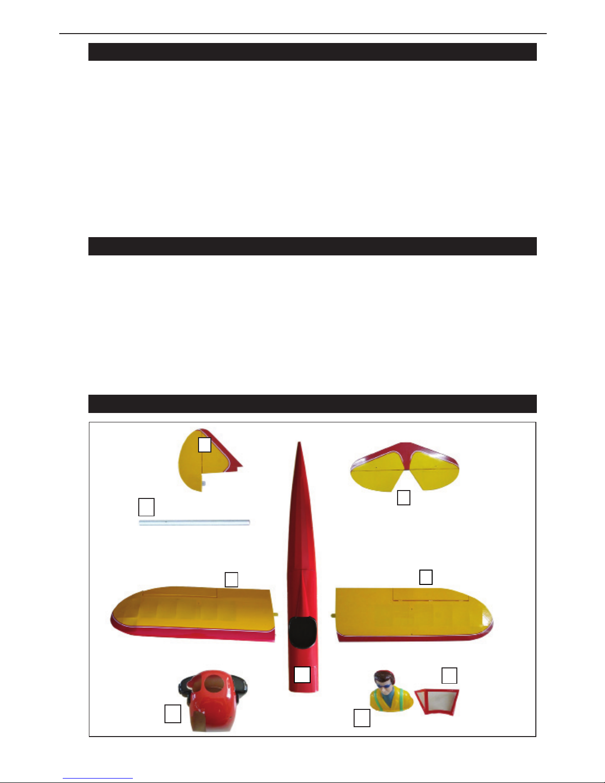
KIT CONTENTS
1
2
3
3
2
4
5
6
7
Please be aware that this aeroplane is not a toy and if assembled or used incorrectly it is
capable of causing injury to people or property. WHEN YOU FLY THIS AEROPLANE YOU
ASSUME ALL RISK & REPONSIBILITY.
If you are inexperienced with basic R/C ight we strongly recommend you contact your R/C
supplier and join your local R/C model Flying Club. R/C Model Flying Clubs oer a variety
of training procedures designed to help the new pilot on his way to successful R/C ight.
ey will also be able to advise on any insurance and safety regulations that may apply.

Instruction Manual.
3
KIT CONTENTS.
SEA238 BOWERS FLYBABY
SEA23801 Fuselage
SEA23802 Wing set
SEA23803 Tail set
SEA23804 Canopy
SEA23805 Pilot
SEA23806 Cowling
SEA23807 Aluminum wing tube
ADDITIONAL ITEMS REQUIRED.
TOOLS & SUPPLIES NEEDED.
in cyanoacrylate glue.
Medium cyanoacrylate glue.
30 minute epoxy.
5 minute epoxy.
Hand or electric drill.
Assorted drill bits.
Modelling knife.
Straight edge ruler.
2mm ball driver.
Phillips head screwdriver.
220 grit sandpaper.
90° square or builder’s triangle.
Wire cutters.
Masking tape & T-pins.
read-lock.
Paper towels.
�10-15cc gasoline engine.
�.61 glow engine.
�1200-1500 Watt Motor and ESC.
�Computer radio with 5 servos.
�Glow plug to suit engine.
�Propeller to suit engine.
�Protective foam rubber for radio
system.
HINGING THE AILERON.
Note : e control surfaces, including the ai-
lerons, elevators, and rudder, are prehinged
with hinges installed, but the hinges are not
glued in place. It is imperative that you prop-
erly adhere the hinges in place per the steps
that follow using a high-quality thin C/A glue.
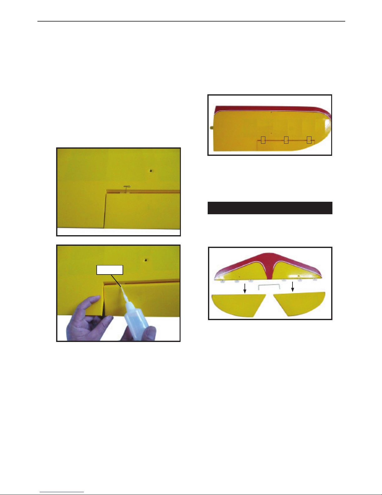
1) Carefully remove the aileron from one
of the wing panels. Note the position of the
hinges.
2) Remove each hinge from the wing panel
and aileron and place a T-pin in the center of
each hinge. Slide each hinge into the wing
panel until the T-pin is snug against the wing
panel. is will help ensure an equal amount
of hinge is on either side of the hinge line
when the aileron is mounted to the aileron.
3) Slide the wing panel on the aileron until
there is only a slight gap. e hinge is now
centered on the wing panel and aileron. Re-
move the T-pins and snug the aileron against
the wing panel. A gap of 1/64” or less should
be maintained between the wing panel and
aileron.
Hinge.
Bowers Flybaby
4
NOTE : e hinge is constructed of a spe-
cial material that allows the C/A to wick
or penetrate and distribute throughout
the hinge, securely bonding it to the wood
structure of the wing panel and aileron.
in CA.
5) Turn the wing panel over and deect the
aileron in the opposite direction from the
opposite side. Apply thin C/A glue to each
hinge, making sure that the C/A penetrates
into both the aileron and wing panel.
6) Using C/A remover/debonder and a pa-
per towel, remove any excess C/A glue that
may have accumulated on the wing or in the
aileron hinge area.
7) Repeat this process with the other wing
panel, securely hinging the aileron in place.
8) Aer both ailerons are securely hinged,
rmly grasp the wing panel and aileron to
make sure the hinges are securely glued and
cannot be pulled out. Do this by carefully ap-
plying medium pressure, trying to separate
the aileron from the wing panel. Use caution
not to crush the wing structure.
Work the aileron up and down sev-
eral times to “work in” the hinges
and check for proper movement.
Note :
4) Deect the aileron and completely satu-
rate each hinge with thin C/A glue. e ailer-
ons front surface should lightly contact the
wing during this procedure. Ideally, when
the hinges are glued in place, a 1/64” gap or
less will be maintained throughout the lengh
of the aileron to the wing panel hinge line.
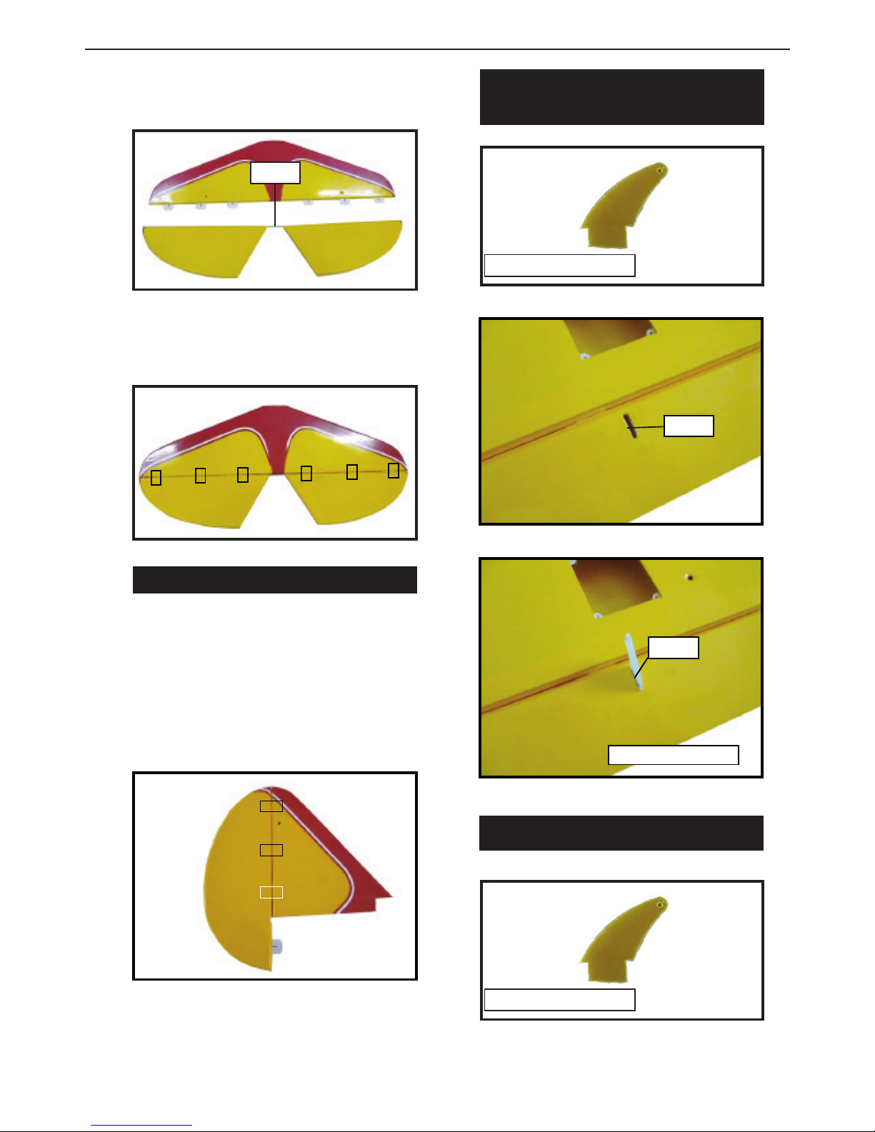
HINGING THE ELEVATORS.
1) Locate the item for this section of the
manual.
2) Carefully remove the elevator from
one of the horizontal stabilizer panels.
Note the position of the hinges.
3) Remove each hinge from the hori-
zontal stabilizer panel and elevator
and place a T-pin in the center of each
hinge. Slide each hinge into the eleva-
tor until the T-pin is snug against the
elevator. is will help ensure an equal
amount of hinge is on either side of the
hinge line when the elevator is mount-
ed to the horizontal stabilizer panel.
Instruction Manual.
5
HINGING THE RUDDER.
Glue the top two rudder hinges in place
using the same techniques used to hinge
the ailerons.
e lower hinge will be glued when the
n/rudder assembly is attached to the fu-
selage.
INSTALL THE AILERONS
CONTROL HORN.
Epoxy.
Using epoxy, Install elevator joiner wire
into both elevator halves.
Glue the elevator hinges in place using the
same techniques used to hing the ailerons.
Epoxy.
Epoxy.
Aileron control horn.
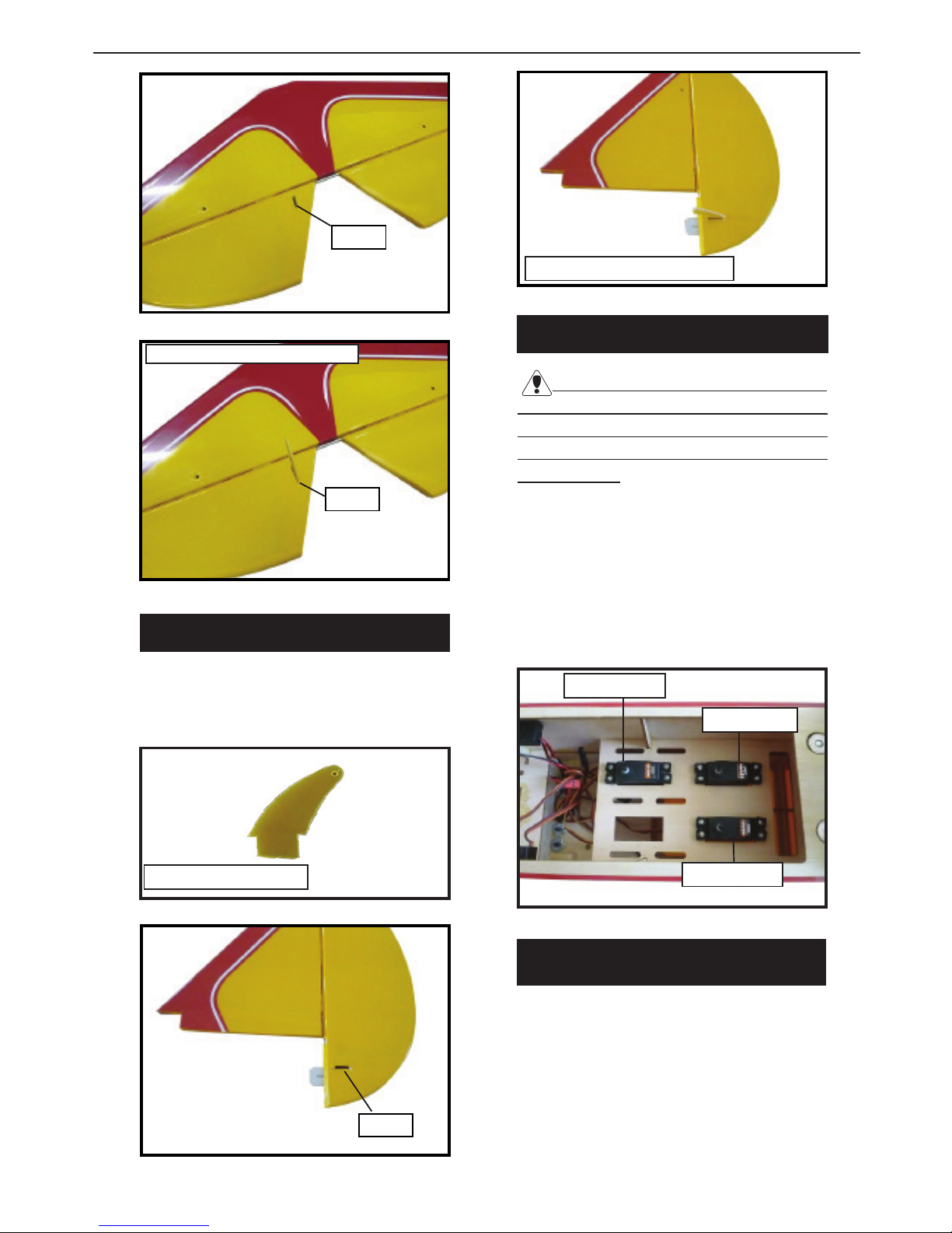
INSTALL ELEVATOR CONTROL HORN.
Fiberglass control horn
Fiberglass control horn
Bowers Flybaby
6
Elevator berglass control horn.
Epoxy.
INSTALL RUDDER CONTROL HORN.
Repeat steps to install the rudder control
horn as same as steps done for ailerons.
Epoxy.
Rudder berglass control horn.
INSTALLING THE FUSELAGE SERVOS.
.
Because the size of servos dier, you
may need to adjust the size of the precut
opening in the mount. e notch in the
sides of the mount allow the servo lead to
pass through.
1) Install the rubber grommets and brass
collets into all servos. Test t the servos
into the fuselage servo mounts.
2) Secure the servos with the screws pro-
vided with your radio system.
Rudder servo.
rottle servo.
Elevator servo.
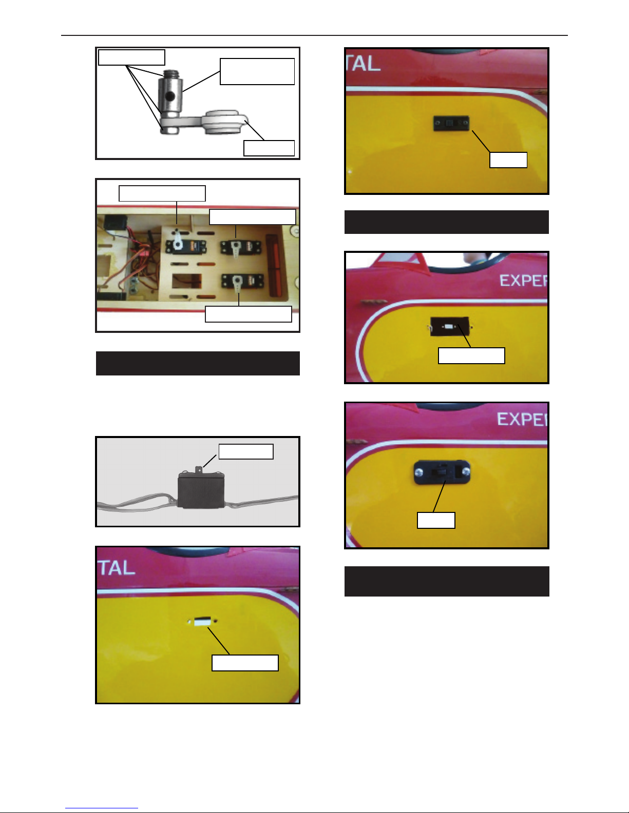
THROTTLE SERVO ARM
INSTALLATION.
Install adjustable servo connector in the
servo arm as same as picture below:
Epoxy.
Fiberglass control horn
Instruction Manual.
7
Servo arm.
Adjustable servo
connector.
Loctite secure.
rottle servo arm.
Elevator servo arm.
Rudder servo arm.
Trim and cut.
.
Switch.
INSTALLING THE ENGINE SWITCH.
Trim and cut.
INSTALLING THE RECEIVER SWITCH.
Install the switch into the precut hole in
the side, in the fuselage.
3/32” Hole.
Switch.
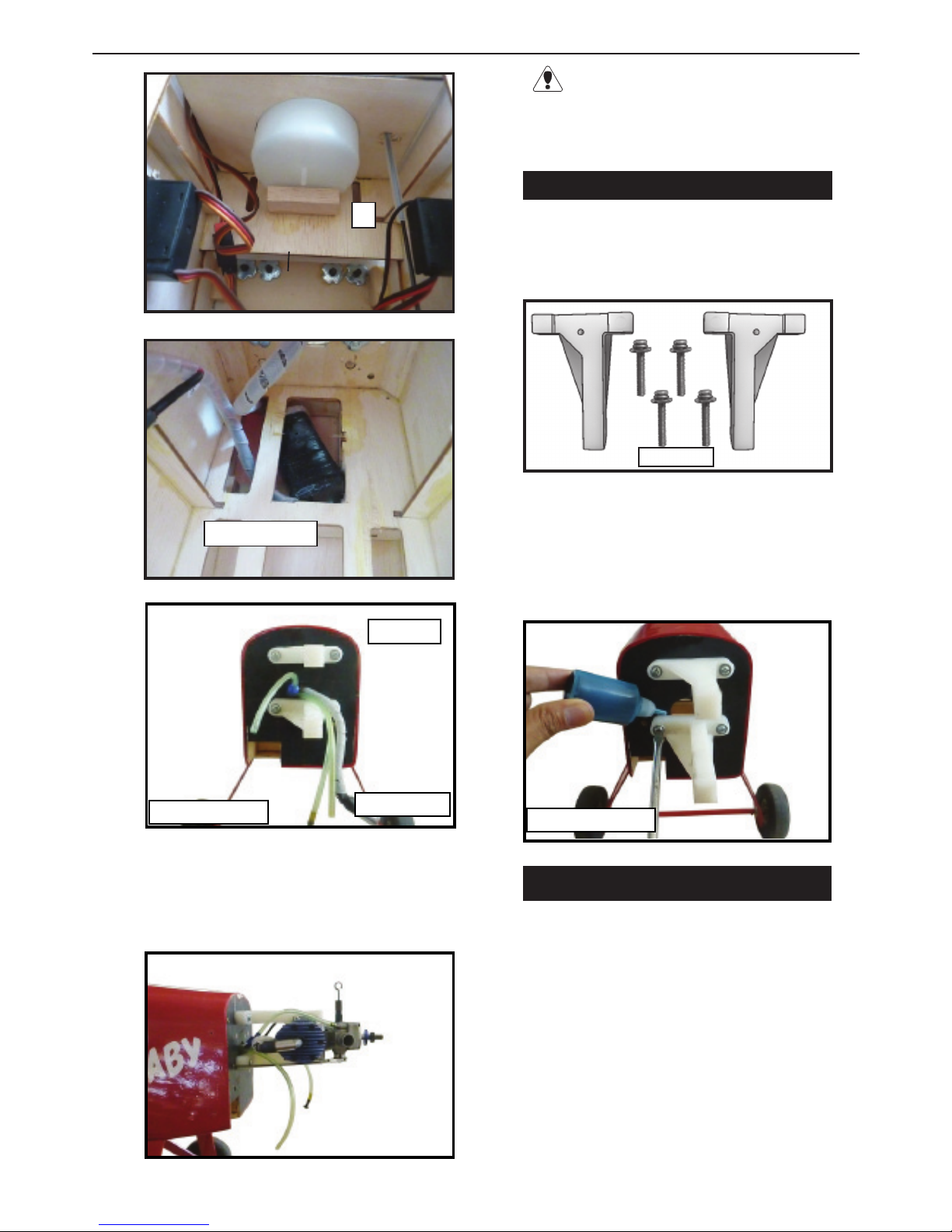
INSTALLING THE STOPPER
ASSEMBLY.
1) Using a modeling knife, carefully cut
o the rear portion of one of the 3 nylon
tubes leaving 1/2” protruding from the
rear of the stopper. is will be the fuel
pick up tube.
2) Using a modeling knife, cut one length
of silicon fuel line. Connect one end of
the line to the weighted fuel pick up and
the other end to the nylon pick up tube.

Bowers Flybaby
8
A
B
3) Carefully bend the second nylon tube up
at a 45º angle. is tube is the vent tube.
4) Test t the stopper assembly into the tank.
It may be necessary to remove some of the
ashing around the tank opening using a
modeling knife. If ashing is present, make
sure none falls into the tank.
5) With the stopper assembly in place, the
weighted pick-up should rest away from the
rear of the tank and move freely inside the
tank. e top of the vent tube should rest just
below the top of the tank. It should not touch
the top of the tank.
6) When satised with the alignment of the
stopper assembly tighten the 3 x 20mm ma-
chine screw until the rubber stopper expands
and seals the tank opening. Do not over-
tighten the assembly as this could cause the
tank to split.
FUEL TANK INSTALLATION.
You should mark which tube is the vent
and which is the fuel pickup when you attach
fuel tubing to the tubes in the stopper. Once the
tank is installed inside the fuselage, it may be
dicult to determine which is which.
7) Slide the fuel tank into the fuselage. Guide
the lines from the tank through the hole in
the rewall.
8) Use plywood template to hold in place the
fuel tank with C/A glue to secure the fuel
tank inside the fuselage.
Vent tube. Fuel pick up tube.
Fuel fill tube.
A
Instruction Manual.
9
B
Ignition Module.
9) Connect the lines from the tank to the en-
gine and muer. e vent line will connect
to the muer and the line from the clunk to
the carburetor.
Blow through one of the lines to ensure
the fuel lines have not become kinked inside
the fuel tank compartment. Air should ow
through easily.
Vent tube.
Fuel pick up tube. Fuel ll tube.
.
ENGINE MOUNT INSTALLATION.
1) Locate the items necessary to install
the engine mount included with your
model.
4x30mm
2) Use four 4x30mm head bolts and four
4mm washers to attach the engine mount
rails to the rewall. Tighten the screws .
Make sure to use threadlock on the screws
to help prevent them from vibrating loose.
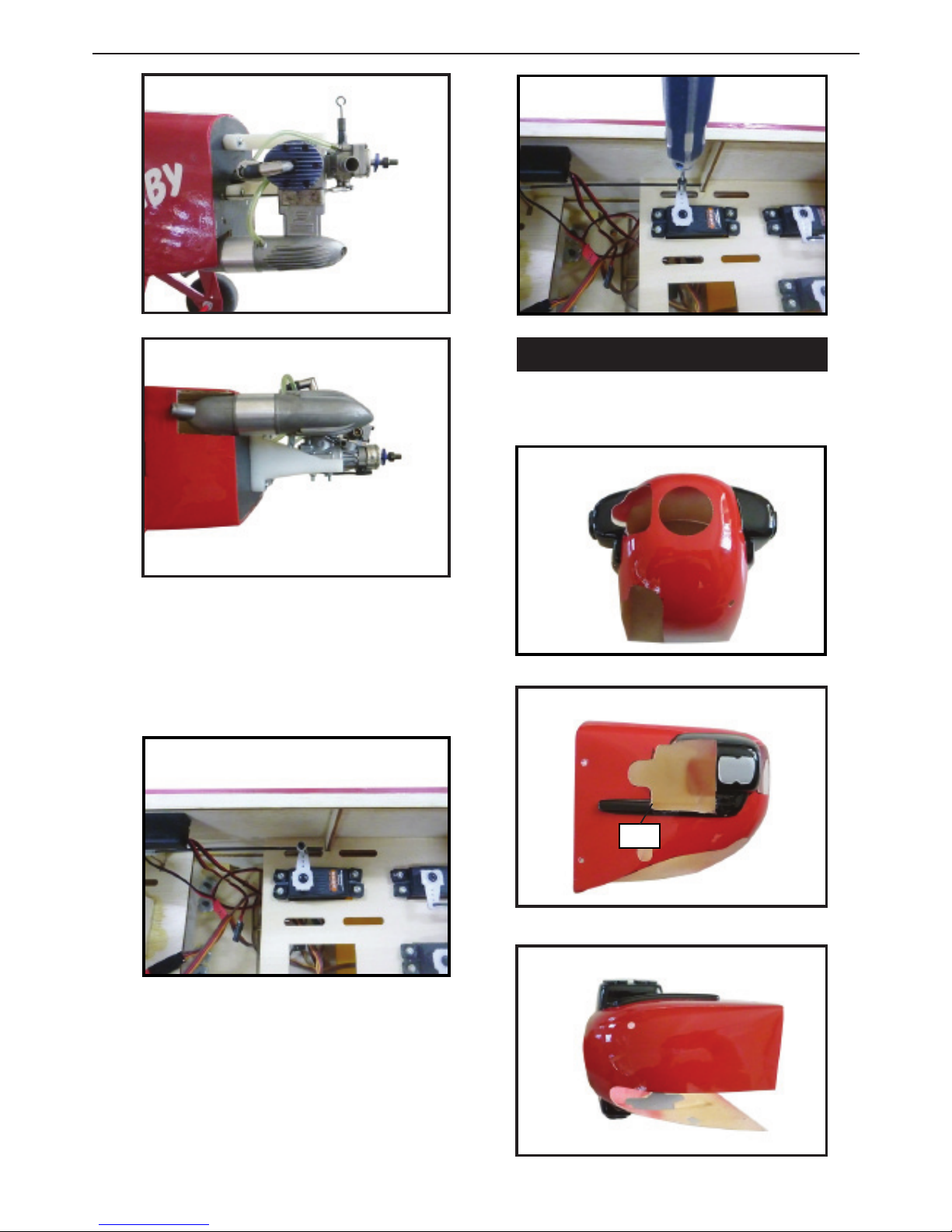
MOUNTING THE ENGINE.
1) Position the engine with the drive
washer (145mm) forward of the rewall
as shown.
read locker glue.

Bowers Flybaby
10
2) Use a pin drill and 4mm drill bit to
drill a small indentation in the mount for
the engine mounting screw.
3) Use a drill to drill the four holes in the
engine mount rails.
4mm
Machine screw M4x30mm
4) On the re wall has the location for the
throttle pushrod tube (pre-drill).
5) Slide the pushrod tube in the rewall
and guide it through the fuel tank mount.
Use medium C/A to glue the tube to the
rewall and the fuel tank mount.
6) Connect the Z-bend in the 450mm
throttle pushrod to the outer hole of the
carburetor arm.
7) Slide the throttle pushrod wire into
the tube. Position the engine between the
mounts. Use four M4x30mm machine
screws to secure the engine to the mount
as shown.
Pushrod wire.
4mm
145mm
Instruction Manual.
11
8) Reinstall the servo horn by sliding the
connector over the pushrod wire. Cent-
er the throttle stick and trim and install
the servo horn perpendiular to the servo
center line.
9) Move the throttle stick to the closed po-
sition and move the carburetor to closed.
Use a 2.5mm hex wrench to tighten the
screw that secures the throttle pushrod
wire. Make sure to use threadlock on the
screw so it does not vibrate loose.
COWLING.
Please see below pictures.
Cut.

Bowers Flybaby
12
Because of the size of the cowl, it may be nec-
essary to use a needle valve extension for the
high speed needle valve. Make this out of suf-
cient length 1.5mm wire and install it into
the end of the needle valve. Secure the wire in
place by tightening the set screw in the side of
the needle valve.
1) With the muer, needle valve, and spark/
glow plug removed from the engine, slide
the cowl in place over the engine. Temporar-
ily install the propeller and spinner in order
to nd the exact location of the cowl. When
satised with the cowl placement, secure the
cowl to the fuselage using masking tape.
Needle valve.
3x10mm
2) Install the muer and muer extension
onto the engine and make the cutout in the
cowl for muer clearance. Connect the fuel
and pressure lines to the carburetor, muer
and fuel ller valve. Secure the cowl to fuse-
lage using the M3x10mm screws.
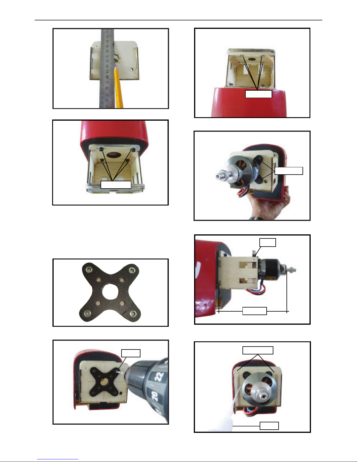
ELECTRIC POWER CONVERSION.
1) Locate the items neccessary to install
the electric power conversion included
with your model.
2) Recommend the items necessary to in-
stall the electric power conversion parts
included with your model.
- Motor: 1200-1500 Watts
- Propeller: 14x8 ~ 16x10
- ESC: 60A
- 5S- 7S Lipo
3) Attach the electric motor box to the
rewall suitable with the cross lines
drawn on the electric motor box and
rewall. Using epoxy and balsa stick
to secure the motor box to the rewall.
Please see pictures below.
Instruction Manual.
13
4) Attach the motor to the front of the
electric motor box using four 4mm blind
nut, four M3x12mm hex head bolts to se-
cure the motor. Please see picture shown.
M4x20mm
4 mm
.
Blind nut.
M3x15mm
145 mm
Epoxy
Balsa stick.
Epoxy
Bowers Flybaby
14
5) Attach the speed control to the side
of the motor box using two-sided tape
and tie wraps. Connect the appropriate
leads from the speed control to the mo-
tor. Make sure the leads will not interfere
with the operation of the motor.
Tie wraps.
INSTALLING THE SPINNER.
e propeller should not touch any
part of the spinner cone. If it does, use a
sharp modeling knife and carefully trim
away the spinner cone where the propel-
ler comes in contact with it.
Install the spinner backplate, propeller
and spinner cone.
INSTALLING THE AILERON SERVOS.
Battery.
Speed control.

Instruction Manual.
15
Servos
.
Small weight
.
Thread
Because the size of servos dier, you
may need to adjust the size of the precut
opening in the mount. e notch in the
sides of the mount allow the servo lead to
pass through.
1) Using a small weight (Weighted fuel
pick-up works well) and string, feed the
string through the wing as indicated.
2) Place the servo between the mounting
blocks and space it from the hatch. Use a
pencil to mark the mounting hole loca-
tions on the blocks.
Small weight. String.
4) Apply 2-3 drops of thin C/A to each
of the mounting holes. Allow the C/A to
cure without using accelerator.
C/A glue
5) Use dental oss to secure the connec-
tion so they cannot become unplugged.
6) Secure the servo to the aileron hatch
using Phillips screwdriver and the screws
provided with the servo.
7) Apply 1-2 drops of thin C/A to each of
the mounting tabs. Allow the C/A to cure
without using accelerator.
3) Use drill bit in a pin vise to drill the
mouting holes in the blocks. C/A glue
Bowers Flybaby
16
8) Remove the string from the wing at the
servo location and use the tape to attach it
to the servo extension lead. Pull the lead
through the wing and remove the string.
9) Set the aileron hatch in place and use a
Phillips screw driver to install it with four
wood screws.
M2x10mm

Instruction Manual.
17
.
.
AILERON PUSHROD HORN
INSTALLATION.
Please see below pictures.
Use a felt tip pen to mark the wire where
it crosses the hole. Use a pair of pliers to
put a shrp 90-degree bend in the wire at
the mark.
Mark.
8mm
M2 lock nut.
Metal clevis.
Snap keeper.
Snap keeper.
Servo arm.
Fuel tubing.
Hex Nut.
Nylon Snap keeper.
Bend at the mark 1) e blind nuts for securing the land-
ing gear are already mounted inside the
fuselage.
2) Using the hardware provided, mount
the main landing gear to the fuselage.
3) Place the fuselage inverted on the
workbench in a suitable stand. Set the
landing gear in place and use a screw-
drive to secure the landing gear to the fu-
selage using bolts M4x20mm and wash-
ers. Make sure to use the threadlock on
the bolts so they don’t vibrate loose.
INSTALLING THE MAIN LANDING
GEAR TO FUSELAGE.
Bowers Flybaby
18
M4x20mm
Collar.
M4x20mm
read locker glue.
Collar.
Collar.

Instruction Manual.
19
INSTALLING WHEELS.
Collar.
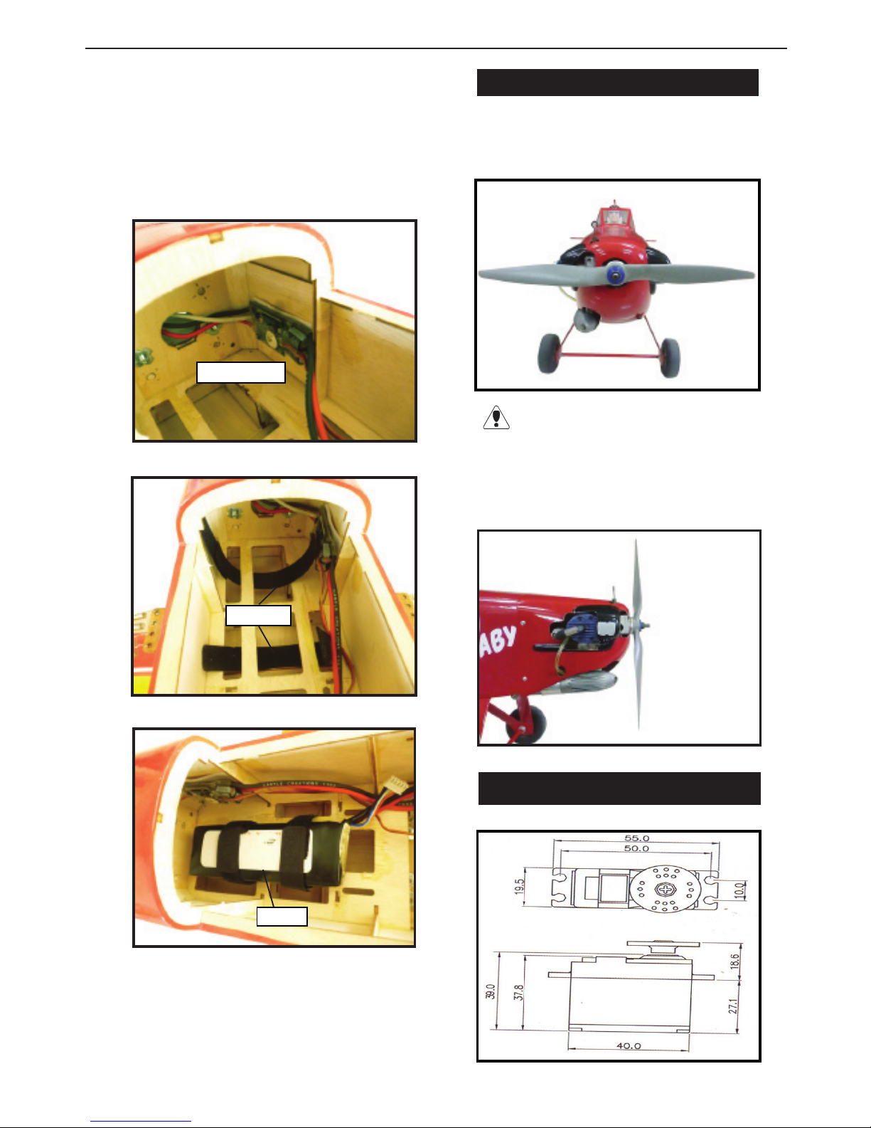
INSTALLING THE HORIZONTAL
STABILIZER.
1) Using a ruler and a pen, locate the cen-
terline of the horizontal stabilizer, at the
trailing edge, and place a mark. Use a tri-
angle and extend this mark, from back to
front, across the top of the stabilizer. Also
extend this mark down the back of the
trailing edge of the stabilizer.
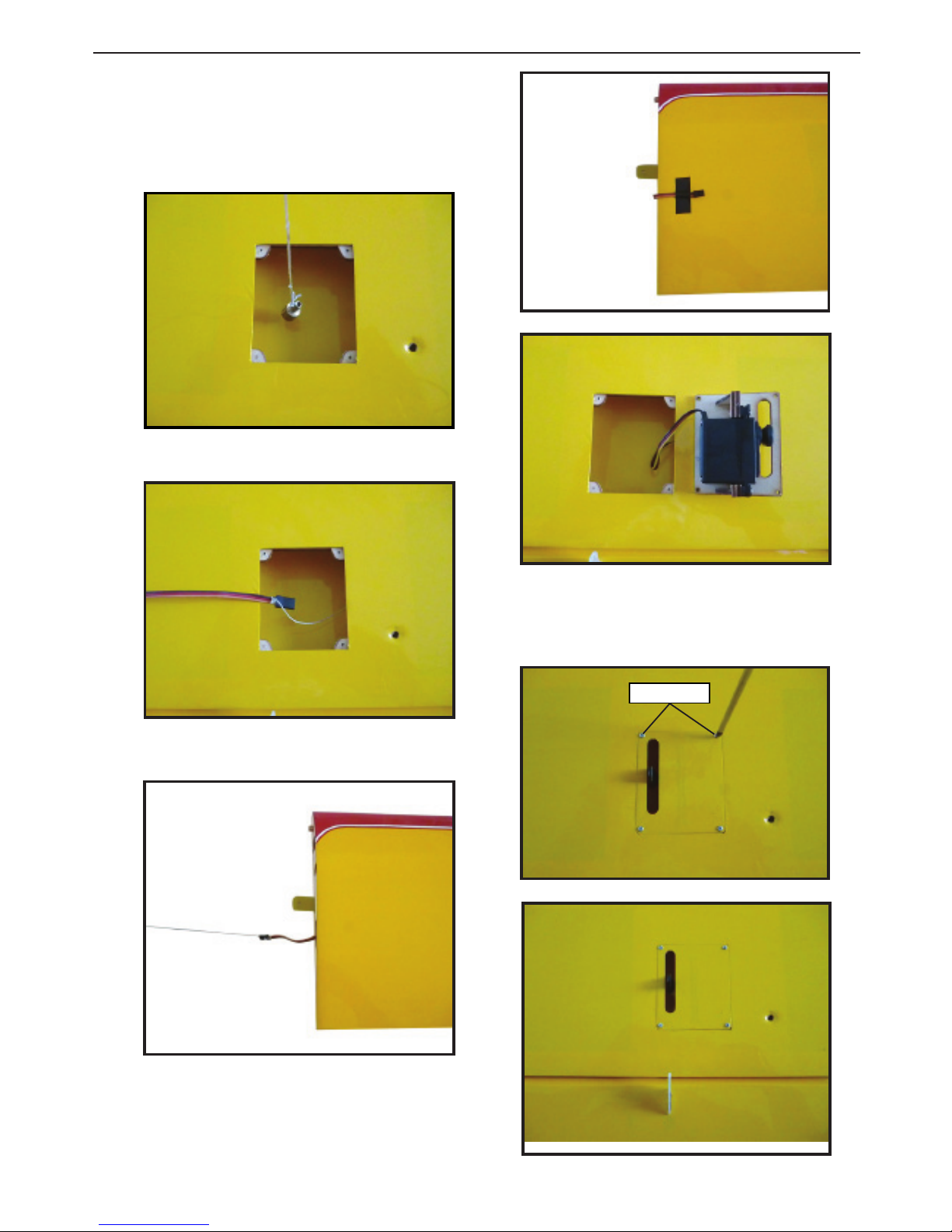
2) Using a modeling knife, carefully re-
move the covering at mounting slot of
horizontal stabilizer ( both side of fuse-
lage).
Draw center line
Cut.
Bowers Flybaby
20
5) Remove the stabilizer. Using the lines
you just drew as a guide, carefully remove
the covering from between them using a
modeling knife.
When cutting through the covering
to remove it, cut with only enough pressure
to only cut through the covering itself. Cut-
ting into the balsa structure may weaken
it.
Trim and cut.
6) Using a modeling knife, carefully re-
move the covering that overlaps the sta-
bilizer mounting platform sides in the
fuselage. Remove the covering from both
the top and the bottom of the platform
sides.
Epoxy
7) When you are sure that everything is
aligned correctly, mix up a generous
amount of 30 Minute Epoxy. Apply a thin
layer to the top and bottom of the stabi-
lizer mounting area and to the stabilizer
mounting platform sides in the fuselage.
Slide the stabilizer in place and realign.
Double check all of your measurements
once more before the epoxy cures. Hold
the stabilizer in place with T-pins or mask-
ing tape and remove any excess epoxy us-
ing a paper towel and rubbing alcohol.
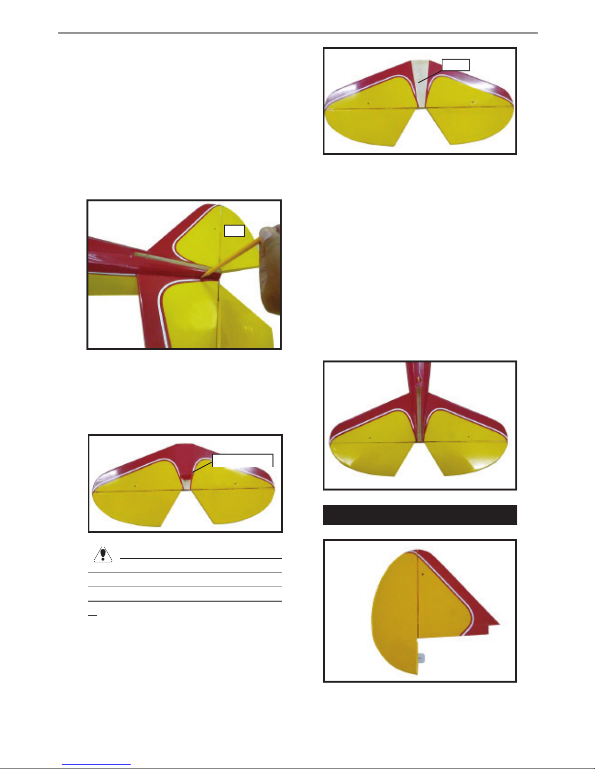
INSTALLING VERTICAL STABILIZER
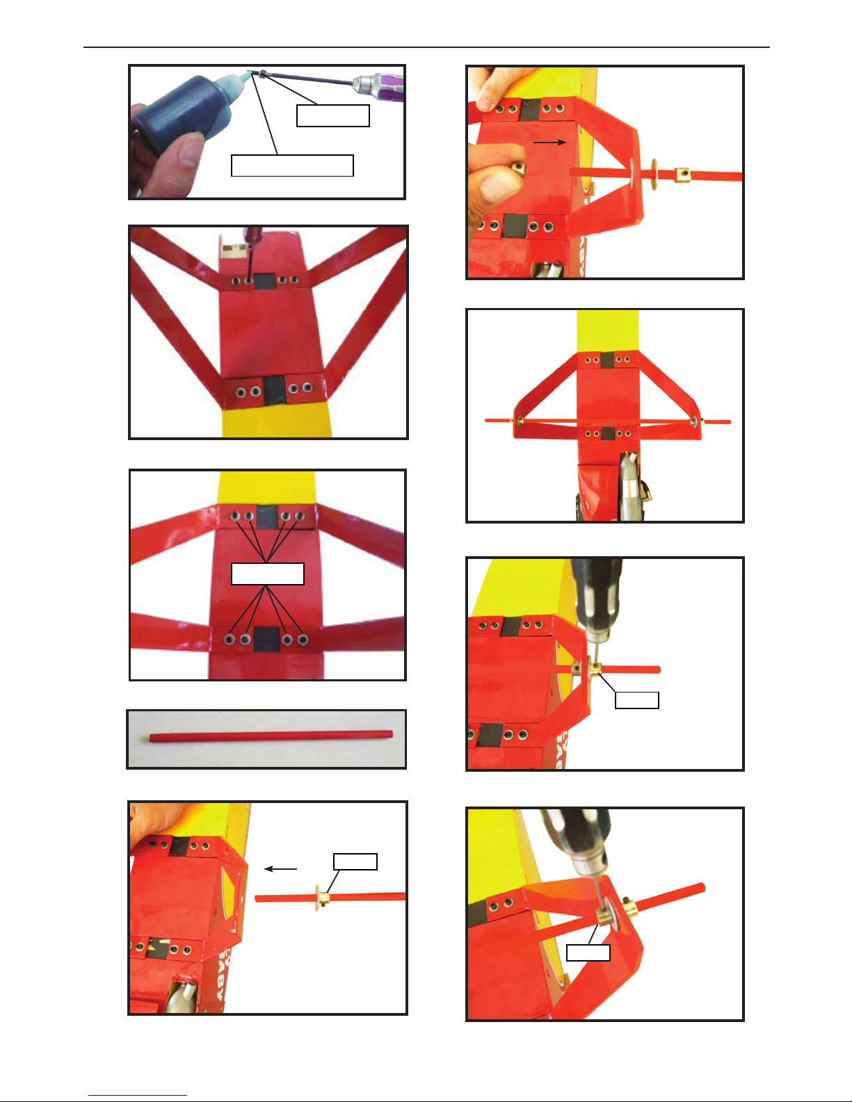
3) Slide the stabilizer into place in the
precut slot in the rear of the fuselage. e
stabilizer should be pushed rmly against
the front of the slot.
4) With the stabilizer held rmly in place,
use a pen and draw lines onto the stabi-
lizer where it and the fuselage sides meet.
Do this on both the right and le sides
and top and bottom of the stabilizer.
Pen
.
Table of contents
Other Seagull Toy manuals


Popular Toy manuals by other brands


Fisher-Price
Fisher-Price P6831 user manual

Little Tikes
Little Tikes Reindeer Carriage Assembly instructions

LEGO
LEGO CREATOR 31069 Leaflet

Faller
Faller 2 OLD-TOWN RELIEF HOUSES Assembly instructions

Hobbico
Hobbico Hobbistar 60 Select instruction manual

LEGO
LEGO Star Wars Cloud City 10123 Building instructions