OPERATION
MANUAL
Product: Document #: Rev: Page:
SEAKEEPER 6 90403 1 7 of 7
Section 1: SYSTEM OVERVIEW
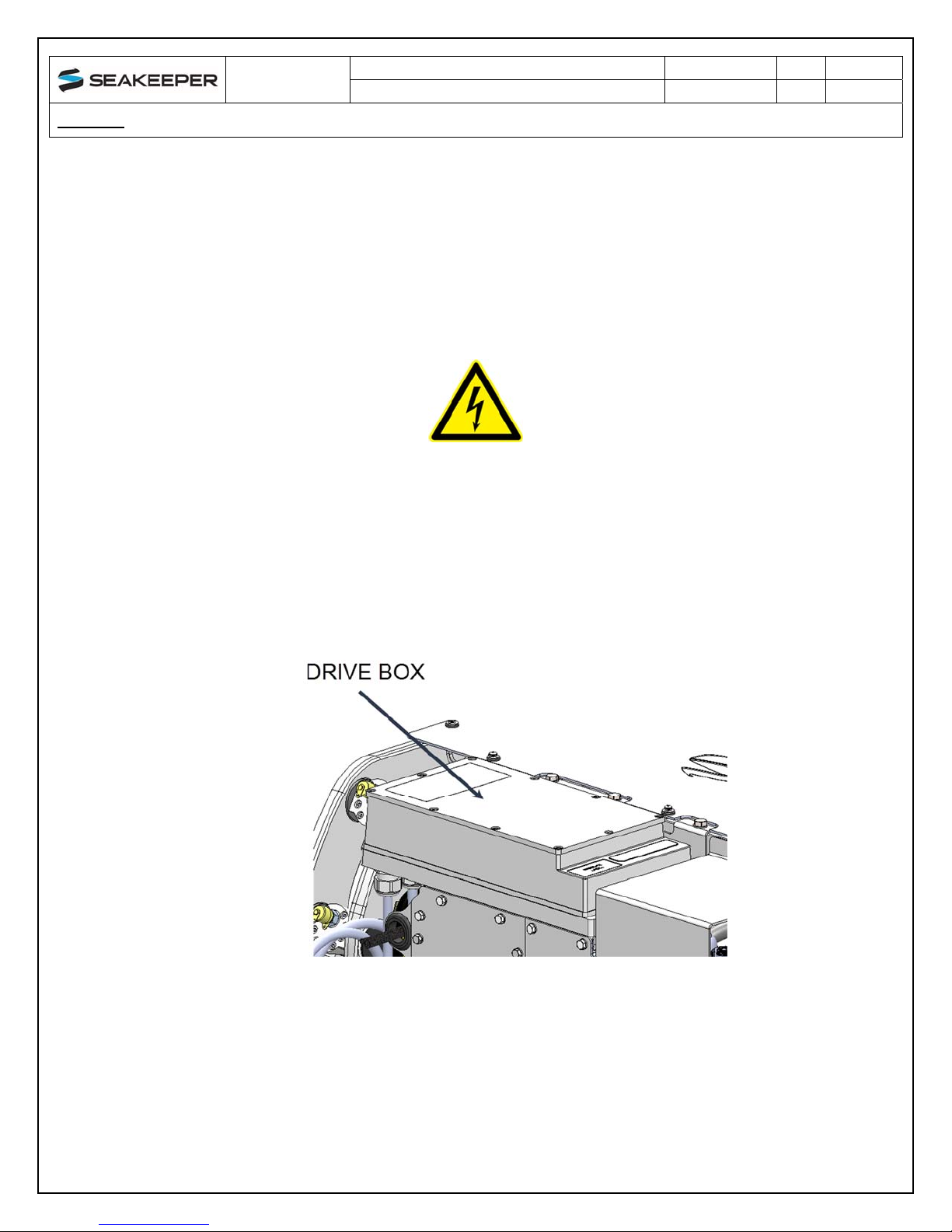
1.4 Electronic Control Module
The Electronic Control Module (ECM) monitors all the system sensors and automatically
regulates operation of the Seakeeper.
The controller commands the motor speed and regulates the Seakeeper’s precession rate and
gimbal angle. This is accomplished by commands to a high response flow control valve in the
hydraulic brake circuit that increases or decreases the brake pressure.
1.5 Inertia Measurement Unit (IMU)
The motion sensor suite in the IMU contains rate sensors that measure the angular movements
of the vessel and accelerometers that measure the vertical and lateral boat movement. These
signals are communicated to the ECM on a CANbus connection inside the Seakeeper’s wiring
harness.
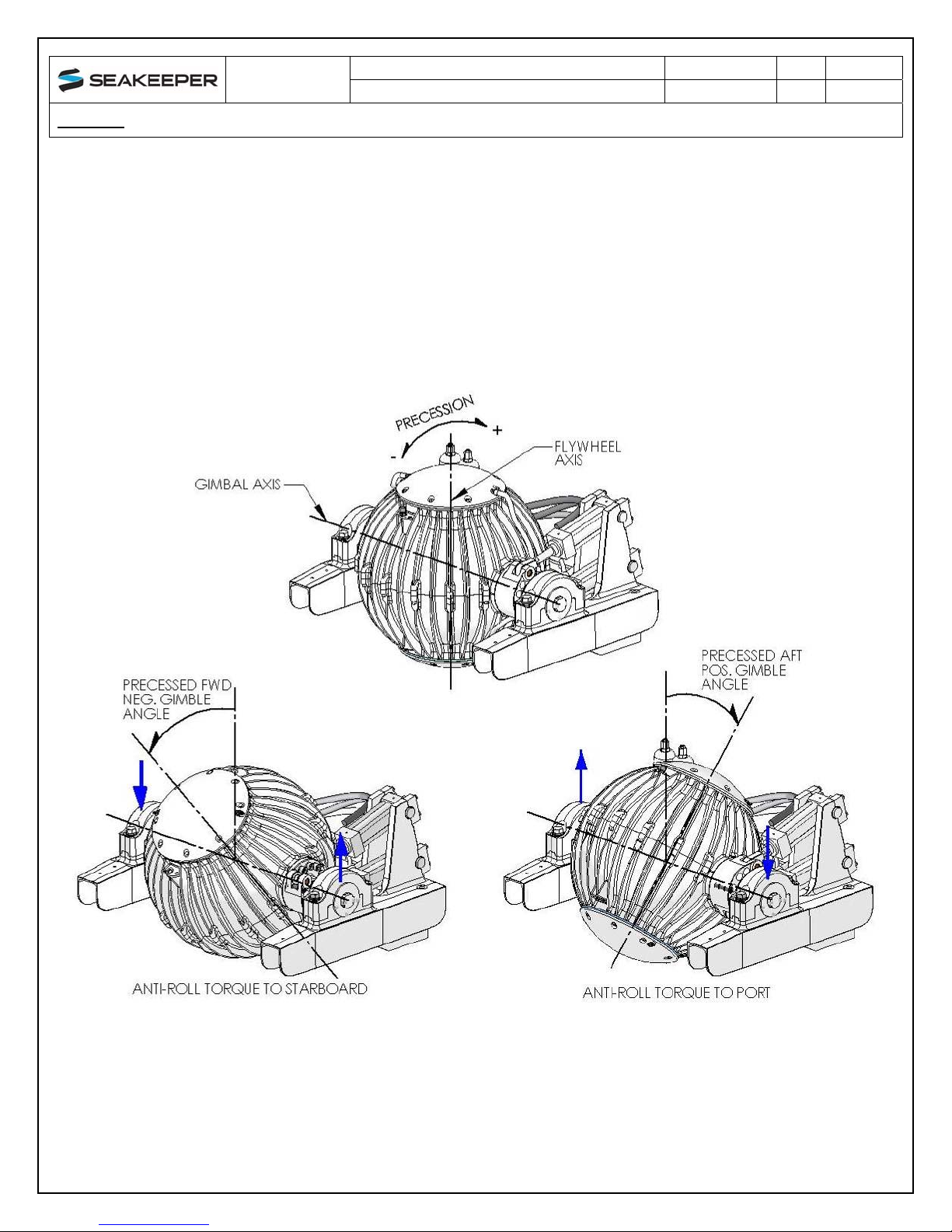
1.6 Brake
The brake mechanism consists of two hydraulic cylinders that attach to a crank arm on the
Seakeeper gimbal shaft. The Seakeeper controller modulates how fast the oil can flow through
a control valve thus controlling the precession rate of the Seakeeper.
The brake hydraulic circuit is a pre-charged closed loop – that is, there is no pump, motor or
reservoir in the circuit. Accumulators are installed in the circuit so the precharge pressure does
not increase as the fluid temperature rises due to the braking action. Locking solenoids are
installed in the circuit to lock the Seakeeper so it cannot precess during ‘lock’ mode or if there is
a leak in the circuit or a mechanical problem with the Seakeeper.
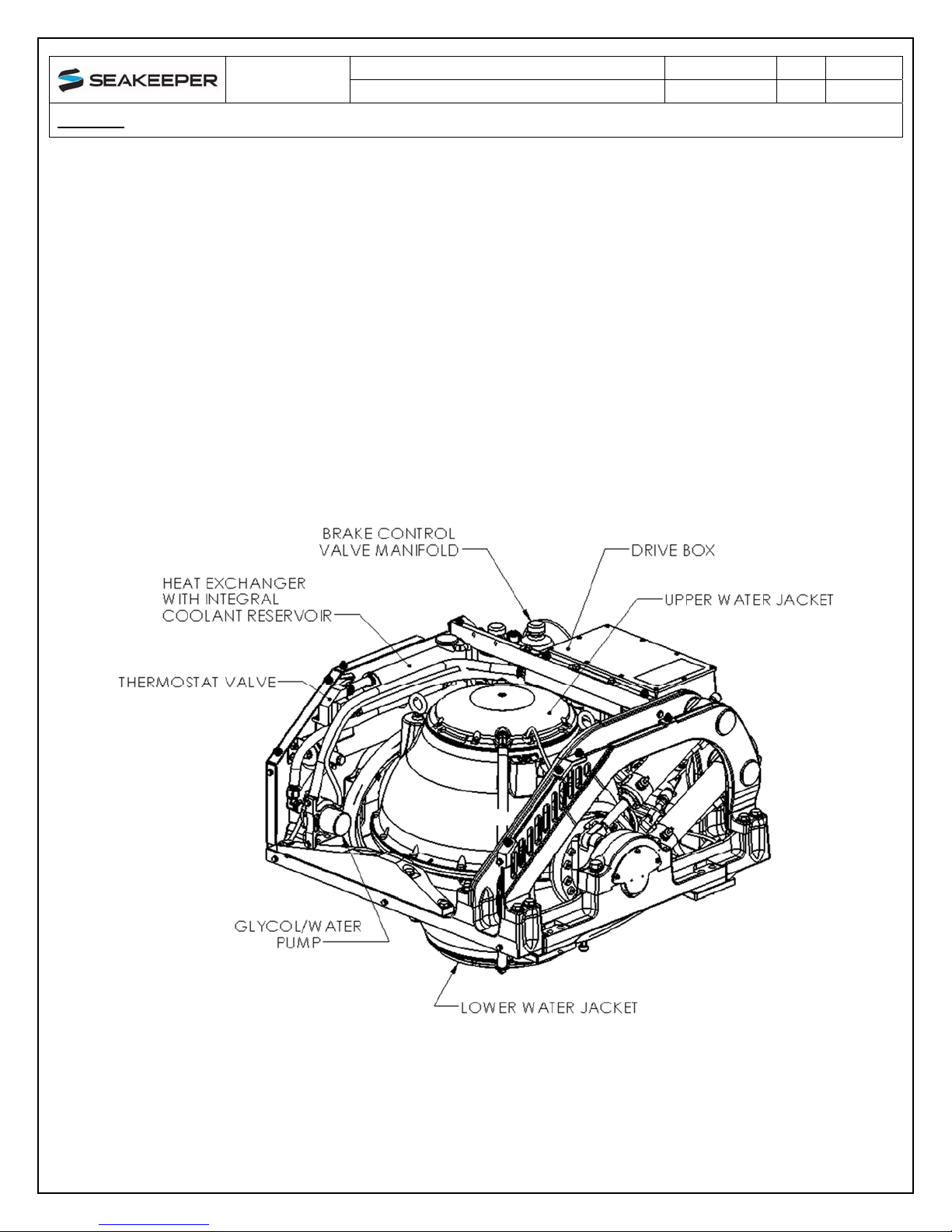
FIGURE 6 – BRAKE SYSTEM COMPONENTS
Seakeeper hydraulic Hand Pump Kit, P/N 10384, is required for servicing the brake system.
Pressure should never be relieved unless this tool is available.