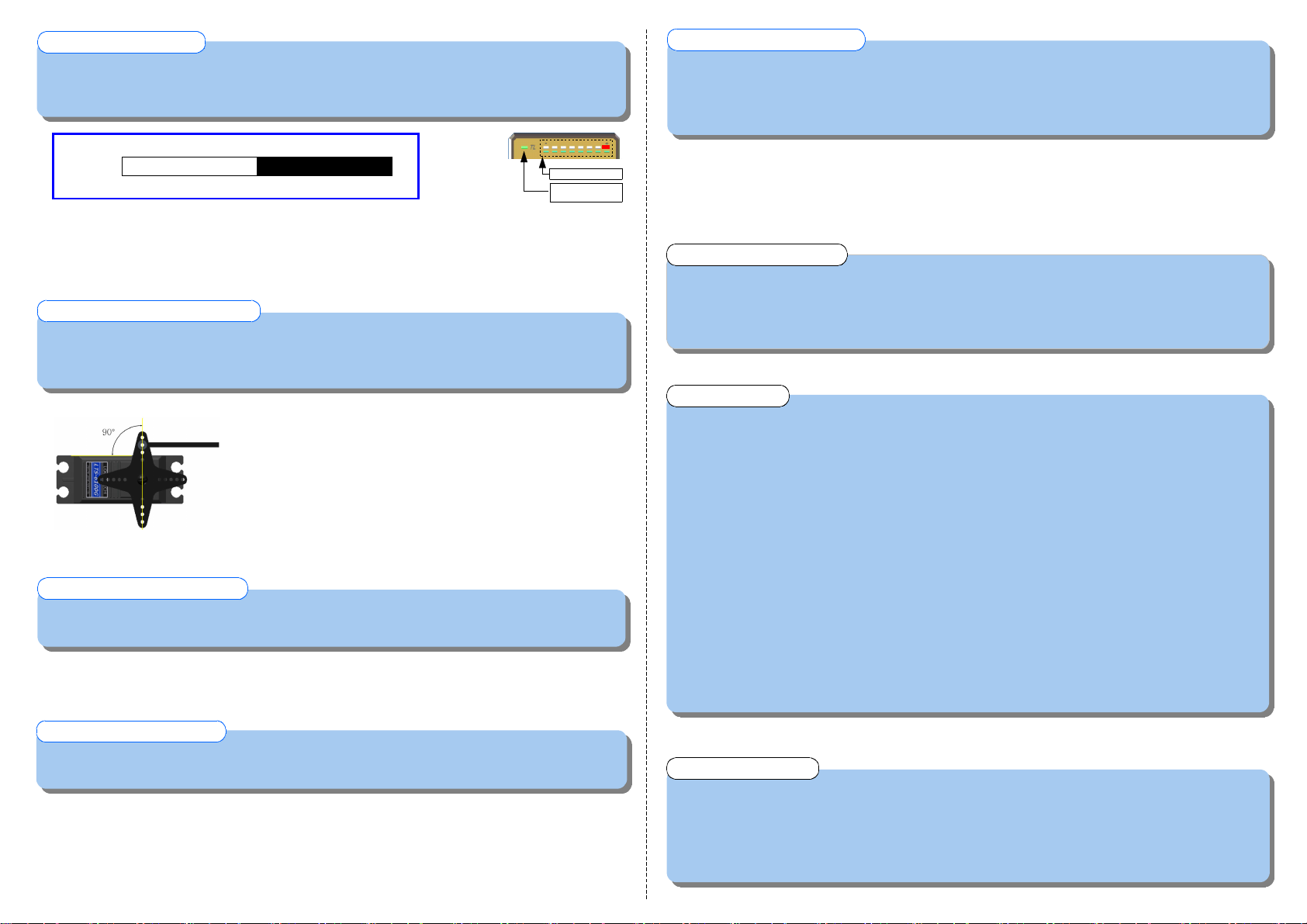
▶ Temporarily set Gain value of Transmitter to NORMAL 30% for adjusting the mechanical neutral.
▶ Gain data selected in Transmitter and real Gain of the gyro recognized has the relation as the below
figure.
STEP 3. GAIN SETTING
▶ This function is to define stick control character and motion speed of Servo.
Break character of the Helicopter and stick response speed could be coordinated.
▶ Fast Servo should be used high value and slow Servo should be used low value.
▶ LED #1: The most slow response LED #8: The most fast response
STEP 7. ROTATE RATE SETTING
▶ Adjust mechanical neutral so as not to be occurred Tail Drift in flying.
▶ Adjust the Linkage length repeatedly with hovering until the Tail has stopping almost in one point.
▶ If Helicopter rotate very quickly to the one direction taking off, Try STEP 5 first.
STEP 4. ADJUST MECHANICAL CENTER
▷ When powered on, LTG-2100T indicates the checked errors on the LED through self-diagnosis function.
LED #1 flickering : error of Sensor
LED #2 flickering : non-input RUDD signal or abnormal input.
LED #3 flickering : non-input GAIN signal or abnormal input.
◈ SELF-DIAGNOSIS FUNCTION
▷ Pirouette speed come to Max. in ATV(Traval Adjust) 140%, DUAL RATE 100%.
For the slow speed, lower the DUAL RATE value.(Don't change ATV value)
▷ When stopping after Pirouette, if tail is not stopped at a point or occurrence of bouncing, tune the
ROTATE RATE value appropriately.
▷ By the mechanical tolerance of the Transmitter stick, there is some case which can't be a auto recognizing
of the Receiver type. In this case try again after some increasing or decreasing of RUDD channel minutely.
▷ Helicopter vibration influence much on the Gyro performance.
Try to keep the helicopter condition without vibration.
▷ Be sure not to deliver helicopter vibration to the Gyro body through some other things.
▷ Installation tape should be used only appointed one by Logictech co.,ltd.
And don't change the way of installation and tape itself(size,shape).
▷ If Horn length is used longer In case of slow servo using, you can get the effect of Servo speed
increasing.
▷ If Receiver type selection is wrong, GAIN selected in Transmitter may can be displayed differently or
changed the feeling of stick steering.
◈ Tips
▶ This function is to select Servo control direction.( recommend to be used in need)
▶ LED #1: N O R M A L LED #2 : R E V E R S E
STEP 5. SELECT SERVO DIRECTION
▷ Place To Send
☞ Address : (High-tech industry Complex),976-2,WOL-CHUL DONG,BUK-GU,KWANG-JU METROPOLTAN CITY,KOREA
☞ TEL : +82-62-972-9173 FAX : +82-62-972-9174
☞ E - mail : logictech@logictech.co.kr
☞ Web : http://www.logictech.co.kr
◈ After Service
NORMAL MODE TAIL LOCK MODE
Real Gain 100% 0% 100%
Tx Gain 0% 50% 100%
▷ If Transmitter Gain is selected as 0%, Gyro recognize it as NORMAL MODE 100%.if Transmitter Gain is
selected as 100%, Gyro recognize it as TAIL LOCK MODE 100% and TL LED is turn on.
(TL LED is turn off in NORMAL MODE)
▷ GAIN is displayed by 8pcs LED.(LED 1: 0%-30%, LED 2 : 31%-40%......LED 8: 91-100%)
TAIL LOCK : ON
NORMAL : OFF
GAIN DISPLAY
▷ Press MENU button and select DIRECTION.
▷ After holding RUDD stick to the left or right side, press the button and change the data.
▶ This function is to define the Servo moving scope for getting enough lift power of Tail Rotor.
▶ Select RUDD channel of Transmitter to ATV(TRAVAL) 140%, DUAL RATE 100%.
STEP 6. SERVO LIMIT SETTING
▷ Press MENU button and select SERVO LIMIT.
▷ Push the stick slowly to the left limit and press button.(memorized the point)
▷ Push the stick slowly to the right limit and press button.(memorized the point)
▷ After finished SETUP MODE, the Real memorized Limit can be checked.
▷ If the Limit is selected too narrowly, It is reset as default value 25%.
▷ Press MENU button and select ROTATE RATE.
▷ Press the button and Change the data after holding stick to the left or the right side.
▷ Try the pirouette during the hovering and check the stop or the speed-up character and decide the
most appropriate value by changing data in case of need.
▷ Install the linkage so as to the Servo and Horn being 90°.
▷ Use the Horn length around 10 ~ 13.5 mm.
▷ If 90 is not made, adjust minutely by using SUB-TRIM of Transmitter.
※ In this case, Gyro power should be supplied again.
▷ When Linkage length need to be adjusted enough, it is better to move
Servo mount.
▷ Linkage should be moved so softly.


