DEWESOFT E-Mobility DEMO User manual

E-Mobility DEMO
USER MANUAL
1.1 Version of the document

USER MANUAL
E-Mobility DEMO
Table of content:
Table of content: 2
Introduction 4
Content of package 5
Unboxing and storage 6
Removing the demo from case 6
Attaching and detaching the car 6
Recommended Hardware and Software 7
Minimum hardware requirements 7
Recommended hardware 7
Recommended software 7
Connecting to the device 8
Connecting the car 8
Voltage measurement 8
Battery voltage measurement 8
Motor voltage measurement 9
Current measurement 9
Road speed 10
Setting up the software 11
Analog inputs 11
Voltage channel setup 11
Current channel setup 12
Counters 13
Math setup 13
Setting up the car 14
Handling the battery 14
Charging the battery 14
Battery charger operation 15
Remote control operation 16
ESC Low Voltage Cut-Off 17
1.1 Version of the document
2

USER MANUAL
E-Mobility DEMO
Controlling the car 18
Remote control 18
Turning on the remote control 18
Enabling remote control 18
Analog out control 19
Enabling analogue control 19
DEWESoft X analogue control configuration 19
Warranty information 21
Calibration 21
Support 21
Service/repair 21
Restricted Rights 21
Printing History 22
Copyright 22
Trademarks 22
Safety instructions 23
Safety symbols in the manual 23
General Safety Instructions 23
Environmental Considerations 23
Product End-of-Life Handling 23
System and Components Recycling 24
General safety and hazard warnings for all Dewesoft systems 22
1.1 Version of the document
3

USER MANUAL
E-Mobility DEMO
1. Introduction
Thank you for purchasing DEWESoft E-Mobility DEMO. This demo was designed for experimenting,
teaching and demonstration purposes. The demo unit is made of an electric car running on a rolling
road. The Car is a scaled-down representation of an electric car, with Battery, Inverter and a 3 phase
motor. The rolling road is equipped with a Tacho so the speed of the car can be calculated. The car is
attached to the road with standard SIRIUS plastic feet that can be detached so the car can be removed.
Once removed it can be driven as a normal RC Car.
Warning
The LiPo battery included in the set is only charged to storage specified level. Please charge the
battery to full potential before use.
Warning
While the car is running watch out for spinning parts that might catch on body parts or clothes.
The car is very robust so if you are using the car off the base, try not to hit anybody as it might
cause injury.
1.1 Version of the document
4

USER MANUAL
E-Mobility DEMO
2. Content of package
●Peli case 1620
●Compact battery charger (Flat EU plug to IEC320 C7)
●Remote control
●Desert FOX 1:10 4WD Electric car with Current CT’s and Voltage measurement connections
●DSUB25 to SIRIUS connection cable
●Rolling road base with Tacho
●Li-Po Battery: 2S (7,4V), 5000mAh, 20C, Max: 45Wh with XT60 or Dean’s T connector
●Original owners manuals for:
○Remote control
○ESC
○Car
○E3 Charger
1.1 Version of the document
5

USER MANUAL
E-Mobility DEMO
3. Unboxing and storage
Caution
The car is attached to the base for shipping. o avoid breaking the plastic feet, detach the car
prior to removing it from the case.
a. Removing the demo from case
A. To open the Peli case 1620 you must first unlock all 4 latches, two in the front and one on each
side.
B. Upon opening the case lid you can access the remote control and Charger. There is also space
for a USB stick and a large compartment for miscellaneous cables and adapters. Enough space
to store all required SIRIUS accessories, if you choose to transport your measurement equipment
in the same case.
C. By lifting the foam insert in upwards direction, beneath it, you will find the E-Mobility demo unit.
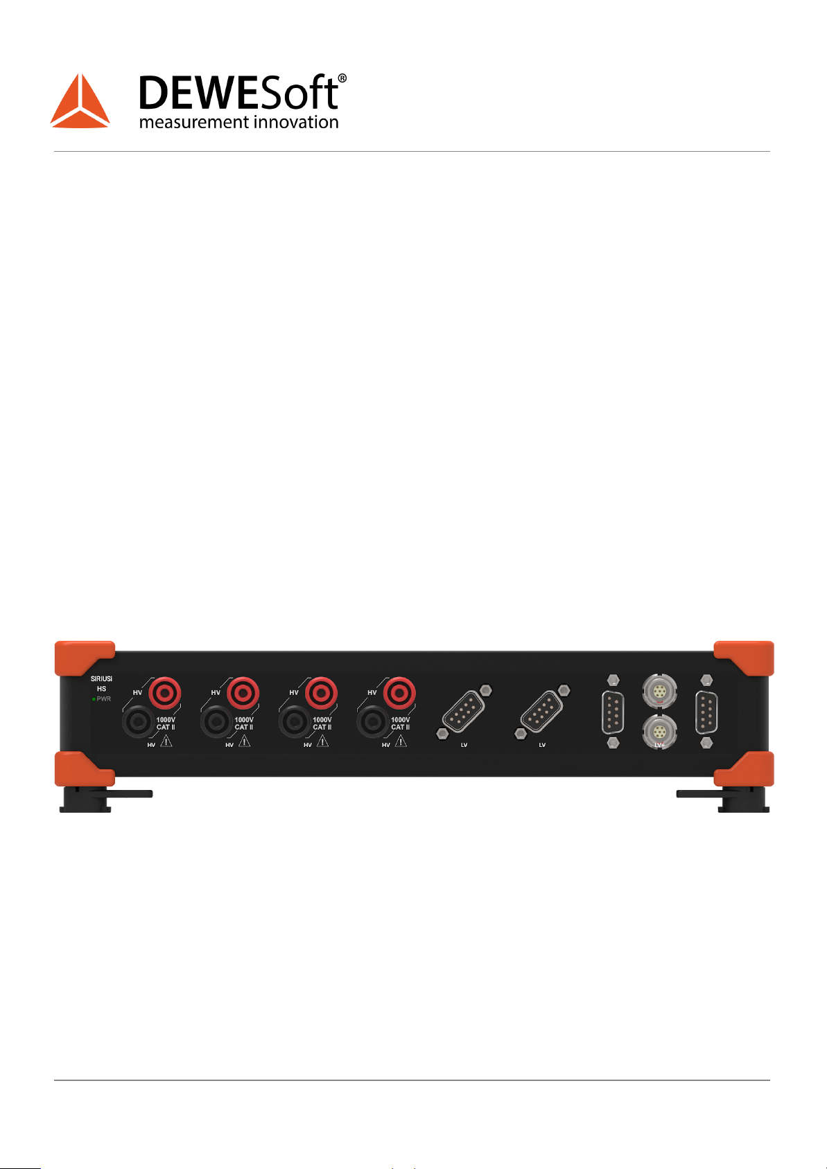
Note that there is still space between the front roller and the base support for a SIRIUS slice with
4x HV, 2x LV, 2x LV+.
D. For storage, please proceed in a reverse manner, by first inserting the base, clipping on the car
and covering it with the foam insert.
b. Attaching and detaching the car
To attach/detach the car to/from the base twist the black plastic lever on each side. To lock rotate
inwards or to unlock rotate outwards as indicated in the pictures:
Unlock:
Lock:
1.1 Version of the document
6

USER MANUAL
E-Mobility DEMO
4.Recommended Hardware and Software
For the use of E-Mobility demo, you will require DEWESoft Hardware, Software and a personal computer
or a Laptop.
Minimum hardware requirements
●4x HV or 4xLV (Banana plugs)
●4x LV or 4x STG or 4x STG-M (DSUB9)
●1x CNT (Lemo 7) or 1x ACC/CHG and 10-30V PSU
Recommended hardware
We recommend the following Hardware as it’s the most likely to be used in a real application.
●SIRIUSi HS of XHS
○4x HV
○2x LV
○2x LV+
○8x AO (For control)
Recommended software
We recommend using the latest version of Dewesoft X with the newest Power module.
The minimum licence you will need is the Power option (DEWESOFT-OPT-POWER) with
DEWESOFT-x-SE or DEWESOFT-x-PROF.
If you want to add and measure with additional sensors, we recommend a custom solution to your
needs or the Enterprise edition with full functionality.
1.1 Version of the document
7

USER MANUAL
E-Mobility DEMO
5. Connecting to the device
a. Connecting the car
To connect the car with the measurement system you first need to connect the Female DSUB 25
connector to the Male DSUB 25 located on the car.
b. Voltage measurement
Battery voltage measurement
To measure the voltage of the battery you need to connect the Green Ubatt and the Black GND banana
plug to HV (banana plug) input.
1.1 Version of the document
8

USER MANUAL
E-Mobility DEMO
Motor voltage measurement
To measure the voltage coming from the inverter you must connect Blue UU, Red UV, and Yellow Uw
banana plug each to its own input and complete the Delta connection with the corresponding cables.
c. Current measurement
To connect the Current transducers from the car to the measurement unit, you need to connect the
DSUB9 connectors to the LV inputs. Each DSUB9 is equipped with a TEDS chip so the channel setup
should be set automatically.
Warning
Excitation of Current Transducers (CT) should not exceed 5V.
1.1 Version of the document
9

USER MANUAL
E-Mobility DEMO
d. Road speed
Road speed is acquired by a single proximity probe providing 5V TTL signal. Connect it to a CNT input
with the Lemo 7 connector.
Note: If your Measurement unit doesn't have a counter input you can rewire it to an analogue input but
note that you will still need to supply power to the Tacho with 10-30VDC.
If your speed drops when the car is accelerating it could be that the distance between the Proximity
probe and the screw located in the roller is too big. To fix this problem use a Hex/Allen screwdriver to
adjust the gap. The recommended gap is 1mm.
When adjusting the screw, watch out that the head of the screw doesn't hit the sensor or the surface
beneath the roller. If this happens you might need to adjust the position of the sensor.
1.1 Version of the document
10

USER MANUAL
E-Mobility DEMO
6.Setting up the software
We recommend that you use the latest version of DEWESoft X, with the newest version of the Power
module. You can download it on our Web page under Support / Downloads.
a. Analog inputs
Voltage channel setup
The car is powered by a 2 cell LiPo battery that has a nominal voltage of 7,4V and a Maximum of 8,4V
when charged. For this reason, you can set the range of Amplifier to 50V when using HV input. We
recommend that your battery voltage is always more than 6,5V to prevent over-discharge.
1.1 Version of the document
11

USER MANUAL
E-Mobility DEMO
Current channel setup
The CT’s output a Maximum of 2,5V so a 10V Amplifier range is sufficient for this measurement.
If TEDS is neither programmed nor recognised, refer to the datasheet table for information:
Configuration: Amplifier
Value
Measurement:
Voltage
Range
10
Low-pass filter
Off
Coupling
DC
Input type
Differential
Excitation
5V
Excitation type
Bipolar
1.1 Version of the document
12

USER MANUAL
E-Mobility DEMO
Configuration: Sensor
Value
Physical quantity
Current
Unit
A
Scaling
By function
Sensitivity (1/k)
0,0125 V/A
Offset
0 A
b. Counters
For setting up the speed go to Ch.setup and add “Counters” module
Math setup
To calculate the speed of the car we can make a formula:
Where:
‘RPMChannel’: Counter input channel in units of RPM
Circumference of roller: 100,48mm
Factor of conversion from m/min to km/h: 0.06
1.1 Version of the document
13

USER MANUAL
E-Mobility DEMO
7.Setting up the car
a. Handling the battery
Warning
The LiPo battery included in the set is only charged to storage specified level. Please charge the
battery to full potential before use.
Warning
When you finish using the demo, ALWAYS DISCONNECT the BATTERY.
Charging the battery
To charge the battery first plug the charger into the main socket and connect the balancing cable from
the battery into the charger. Use the smaller 3 pin port intended for 2S batteries.
1.1 Version of the document
14

USER MANUAL
E-Mobility DEMO
b. Battery charger operation
1.1 Version of the document
15

USER MANUAL
E-Mobility DEMO
c. Remote control operation
1.1 Version of the document
16

USER MANUAL
E-Mobility DEMO
d. ESC Low Voltage Cut-Off
To prevent over-discharge of the battery the ESC will cut power when the voltage limit is reached.
The car’s ESC should be preset to the right configuration for the intended application of use. In case the
ESC was not set correctly please set the Low voltage cut off to 3,0V or higher by the following method:
1.1 Version of the document
17

USER MANUAL
E-Mobility DEMO
8.Controlling the car
There are two ways to operate a car. the first is via the remote control, and the second via the SIRIUS
analog output. If you want to make an automated demo consider the option to control the car with AO.
a. Remote control
Warning
Always turn on the remote control prior to connecting the battery and switching ON the RC Car.
Turning on the remote control
To turn on the remote control open the plastic cover by holding it at the back of the remote and pulling
it upwards. When you open the cover you will be able to switch on the power.
Enabling remote control
To activate the remote control mode move the switch to the forward position as indicated in the
picture.
1.1 Version of the document
18

USER MANUAL
E-Mobility DEMO
b. Analog out control
Enabling analogue control
To activate the Analog input mode move the switch to the backwards position as indicated in the
picture.
DEWESoft X analogue control configuration
Caution
Always set the sampling rate to Maximum frequency. The output sampling rate is dependant on
the sampling rate set in Analog in. If you are using SIRIUS HS, the maximum sampling rate of
Analog out is 250 kS/s.
A. Add user input
1.1 Version of the document
19

USER MANUAL
E-Mobility DEMO
B. Add math modules to simulate PWM
C. Configure Analog OUT
D. Add Automatic Run-up User inputs and Math
1.1 Version of the document
20
Table of contents
Other DEWESOFT Science Education Product manuals
Popular Science Education Product manuals by other brands

CPO Science
CPO Science Physics Stand Assembly instructions

3B
3B B55 manual

Electroflash Resourcing
Electroflash Resourcing Electric Paint manual

ScienceSeeds
ScienceSeeds MAGIC PENNY BOX quick start guide

Quick
Quick MC2X 16k Installation and use manual

Desert Star
Desert Star Acoustic Release Control System manual

Bresser
Bresser ASTRO PLANETARIUM operating instructions

Gaumard
Gaumard NOELLE S554.100 user guide

pitsco
pitsco Solar Designer user guide

Reality Works
Reality Works Cat Skeleton Model quick start guide

Bavarian Demon
Bavarian Demon CORTEX quick start guide

ARBOR SCIENTIFIC
ARBOR SCIENTIFIC Deluxe Van De Graaff Generator instructions