SeaLevel Relio R1 User manual

1
© Sealevel Systems, Inc. R1 Rugged Manual | SL9709 12/2023
Relio
™
R1 Rugged Industrial Computer
User Manual | Relio™R1 Rugged

2
© Sealevel Systems, Inc. R1 Rugged Manual | SL9709 12/2023
Contents
CONTENTS............................................................................................................................................................................................................................2
INTRODUCTION...................................................................................................................................................................................................................4
OVERVIEW ....................................................................................................................................................................4
FEATURES .....................................................................................................................................................................5
BEFORE YOU GET STARTED..............................................................................................................................................................................................6
WHAT’S INCLUDED .........................................................................................................................................................6
ADVISORY CONVENTIONS .................................................................................................................................................6
OPTIONAL ITEMS ............................................................................................................................................................6
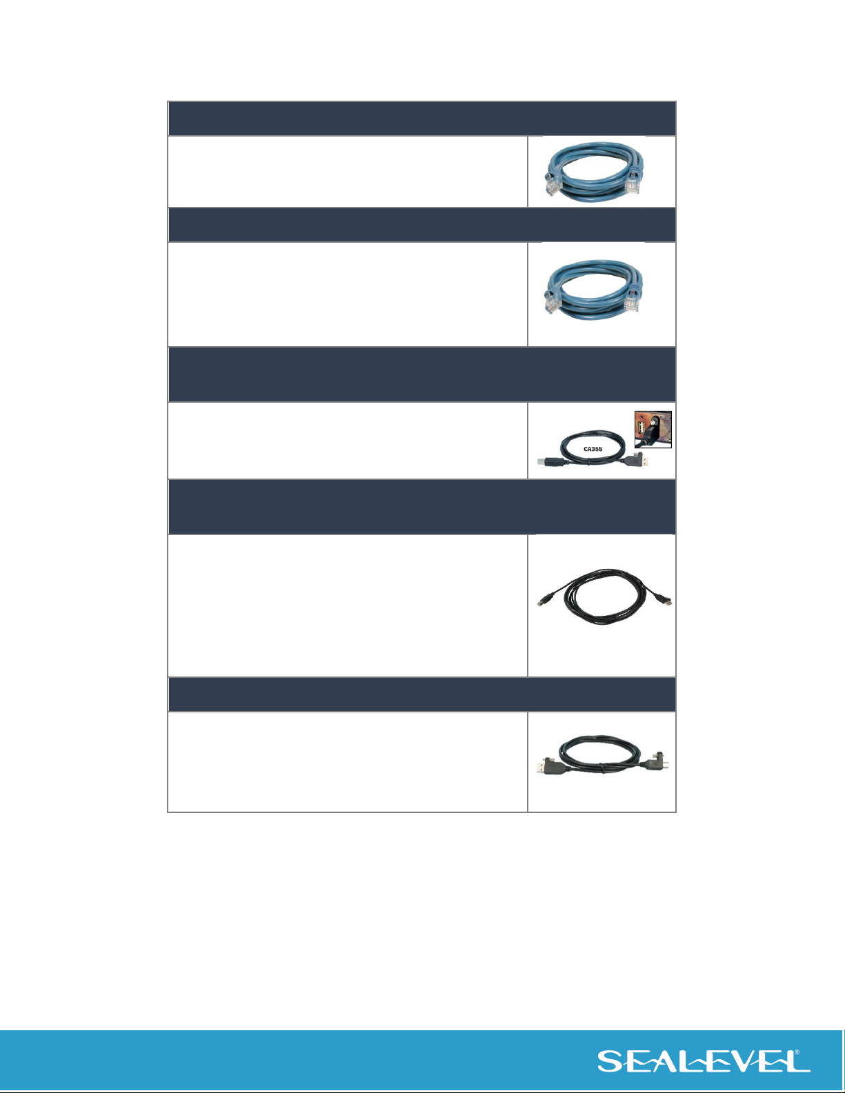
Cables ....................................................................................................................................................................7
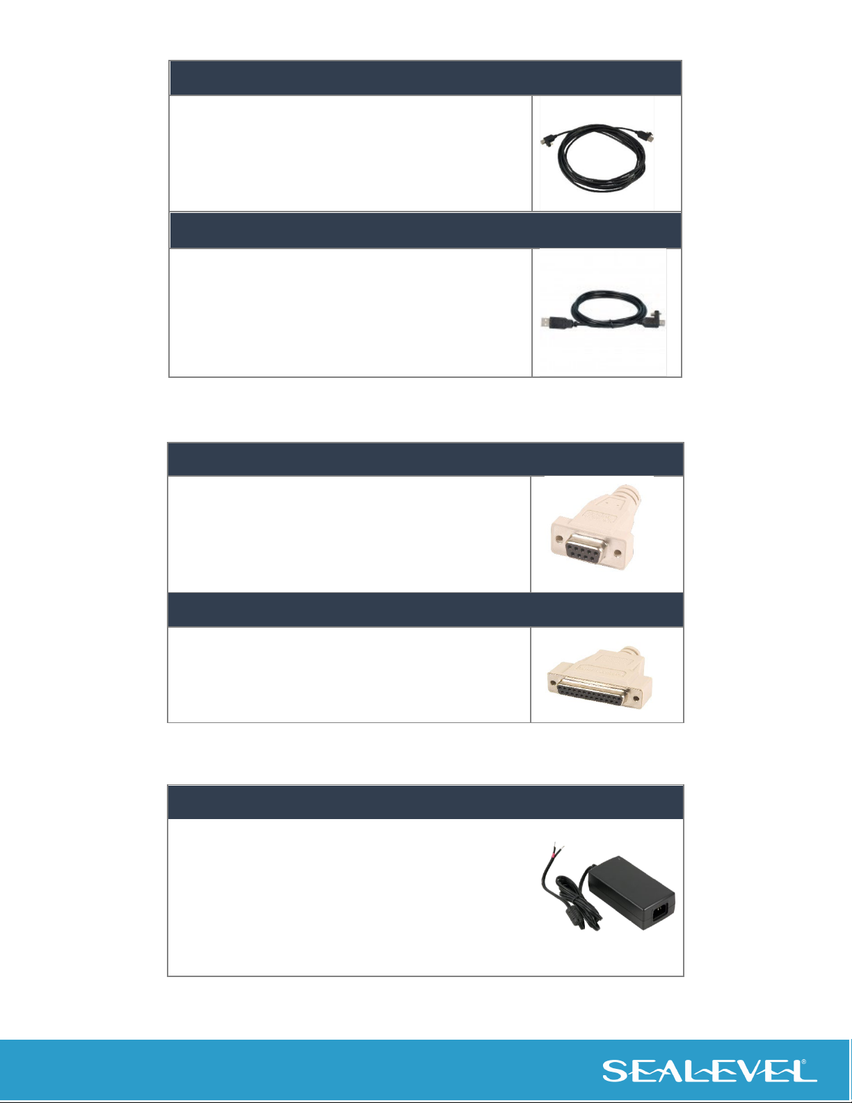
Loopback Adapters ................................................................................................................................................8
Power Supply .........................................................................................................................................................8
TECHNICAL DESCRIPTION................................................................................................................................................................................................9
R1 RUGGED PART NUMBER BREAKDOWN ...........................................................................................................................9
SAMPLE OF ORDERABLE R1 RUGGED PART NUMBERS ...........................................................................................................9
SYSTEM DESCRIPTION......................................................................................................................................................9
COM EXPRESS MODULE/RAM CONFIGURATION OPTIONS ..................................................................................................10
SATA CFAST TYPE I, II MEMORY ...................................................................................................................................10
POWER INPUT..............................................................................................................................................................11
DIGITAL VIDEO OUTPUT.................................................................................................................................................12
ETHERNET ...................................................................................................................................................................12
SERIAL COMMUNICATIONS .............................................................................................................................................12
RS-232/485 Serial Ports .......................................................................................................................................12
RS-485 Termination Resistors ..............................................................................................................................12
RS-232/485 Port 1 and RS-232/485 Port 2 ..........................................................................................................13
USB 2.0 DEVICE AND USB 3.1 DEVICE ............................................................................................................................13
CAN OPERATION .........................................................................................................................................................14
WI-FI OPERATION ........................................................................................................................................................15
CAD REFERENCES.............................................................................................................................................................................................................15
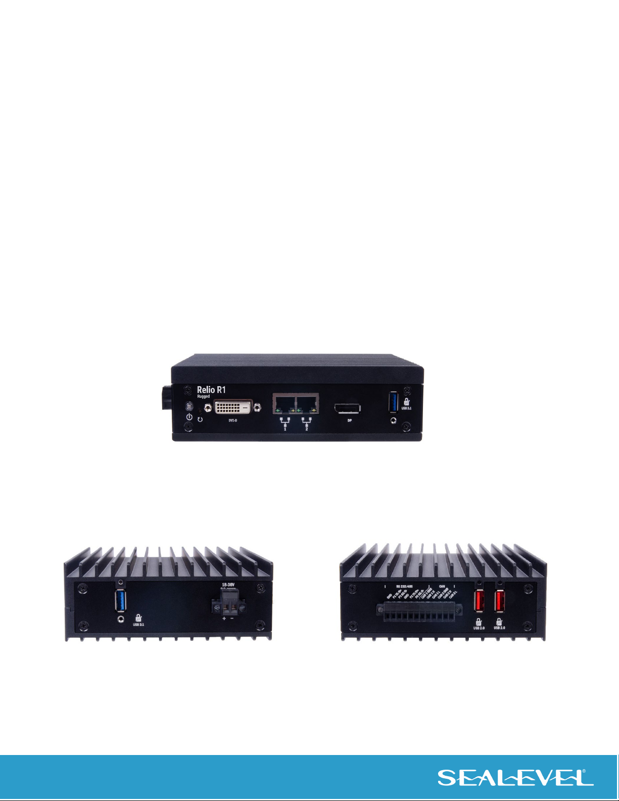
ISOMETRIC VIEW ..........................................................................................................................................................15
FRONT PANEL I/O CONNECTORS .....................................................................................................................................16
RIGHT PANEL I/O CONNECTORS ......................................................................................................................................16
LEFT PANEL I/O CONNECTORS ........................................................................................................................................17
SYSTEM SET-UP.................................................................................................................................................................................................................17
HARDWARE INSTALLATION............................................................................................................................................................................................18
INSTALLATION CONSIDERATIONS......................................................................................................................................18
SOFTWARE INSTALLATION .............................................................................................................................................................................................19
CONGATEC DRIVERS AND MODULE INFORMATION...............................................................................................................19

3
© Sealevel Systems, Inc. R1 Rugged Manual | SL9709 12/2023
ETHERNET DRIVER ........................................................................................................................................................19
SERIAL PORTS ..............................................................................................................................................................19
KVASER CAN CARD (LINUX AND WINDOWS)..................................................................................................................20
SILEX TECHNOLOGY WI-FI CARD (CONTACT THEIR SUPPORT DEPARTMENT FOR DRIVER AVAILABILITY) ...........................................20
SEACOM WINDOWS INSTALLATION.................................................................................................................................20
UPGRADING TO THE CURRENT SEACOM DRIVER .................................................................................................................22
TECHNICAL SPECIFICATIONS ENVIRONMENTAL SPECIFICATIONS.......................................................................................................................23
MECHANICAL DIMENSIONS.............................................................................................................................................23
POWER CONSUMPTION .................................................................................................................................................23
MANUFACTURING.........................................................................................................................................................23
MTBF (TELCORDIA SR-332, ISSUE 4CALCULATION PREDICTION METHOD)..............................................................................23
OPERATING TEMPERATURE RANGE ..................................................................................................................................24
SYSTEM OPERATION........................................................................................................................................................................................................24
POWER AND RESET AND BUTTONS ...................................................................................................................................24
HIGH PERFORMANCE SERIAL COMMUNICATION PORTS ........................................................................................................25
CLOCK MODES AND BAUD RATES ....................................................................................................................................26
SERIAL INTERFACE SELECTION..........................................................................................................................................26
COM Port Configuration ......................................................................................................................................27
RS-485 Enable Modes ..........................................................................................................................................29
Slew Rate Limiting ...............................................................................................................................................29
Receiver Biasing...................................................................................................................................................29
Line Termination Selection via Hardware ............................................................................................................29
RS-485 Auto-Enable Delay ...................................................................................................................................30
APPENDIX A – TROUBLESHOOTING SERIAL COMMUNICATION ISSUES.............................................................................................................31
TROUBLESHOOTING/VERIFICATION FOR ASYNCHRONOUS SERIAL PRODUCTS ............................................................................31
APPENDIX B – HOW TO GET ASSISTANCE..................................................................................................................................................................36
APPENDIX C – COMPLIANCE NOTICES........................................................................................................................................................................ 37
FEDERAL COMMUNICATIONS COMMISSION (FCC) STATEMENT .............................................................................................37
ISED CANADA .............................................................................................................................................................37
EMC DIRECTIVE STATEMENT ..........................................................................................................................................37
APPENDIX D - HANDLING INSTRUCTIONS..................................................................................................................................................................38
APPENDIX E – ELECTRICAL INTERFACE.......................................................................................................................................................................39
RS-232......................................................................................................................................................................39
RS-485......................................................................................................................................................................39
APPENDIX F – ASYNCHRONOUS COMMUNICATIONS .............................................................................................................................................40
WARRANTY ........................................................................................................................................................................................................................41

4
© Sealevel Systems, Inc. R1 Rugged Manual | SL9709 12/2023
Introduction
Overview
The Relio™ R1 Rugged Industrial Computer is an exceptionally rugged embedded computer for operating
in harsh environments. The R1 Rugged’s fanless and nearly cableless structure ensures durability over long-
term use. Built using the PICMG COM Express architecture, Sealevel has partnered with the leading COM
Express module manufacturers to ensure our customers benefit from the best in the industry.
The R1 Rugged is the latest addition to the industry-leading Relio embedded computer line. The R1 Rugged
incorporates the newest generation of industrial processors and a modernized video interface. With
versatile communication options for CAN, Wi-Fi, and RS-232/485, the R1 Rugged features (2) locking USB
3.1 ports, (2) locking USB 2.0 ports, (2) Gigabit Ethernet ports, and an extreme, wide operating temperature
range of up to -40°C to +71°C.
The R1 Rugged has an extreme rugged, anodized aluminum enclosure combined with intentional thermal
management for unmitigated performance under environmental extremes. The fanless, solid-state design,
combined with locking SeaLATCH USB connectors, ensures shock and vibration tolerance as well as long-
term reliability.
With a robust and flexible I/O mix, this rugged industrial computer is capable of managing a variety of data
inputs to interface with legacy systems and the most advanced peripherals. The embedded computer’s
COM Express architecture gives manufacturers a technology migration path to easily change, and upgrade,
the CPU functionality without a complete system redesign or replacement.
Inside the R1 Rugged, a CFAST SATA II card slot provides solid-state storage ranging from 64GB to 256GB.
The R1 Rugged is compatible with Windows 10 IoT Enterprise, Windows 11 Pro, Linux RHEL 8 (or later), and
Linux Ubuntu 21 (or later). The system is also Windows 11 IoT-ready to provide maximum flexibility for
evolving, customer-specific software applications. Sealevel’s SeaCOM hardware driver is included to
support system I/O. Serial application code samples assist with custom application development and
complete support documentation expedites configuration.

5
© Sealevel Systems, Inc. R1 Rugged Manual | SL9709 12/2023
(1) Video DVI-D Port Connector
(2) Gibabit (10/100/1000BaseT) Ethernet Ports
(1) Video DisplayPort Connector
(
1) USB 3.1 SeaLATCH Charging Port
Features
•Up to -40ºC to 71ºC wide operating temperature range
•18-36VDC input with locking 2-position connector
•(2) Gigabit (10/100/1000BaseT) Ethernet Ports
•(2) USB 3.1 SeaLATCH Charging Ports
•(2) USB 2.0 SeaLATCH Ports
•(1) Video DVI-D Port connector
•(1) Video DisplayPort connector
•(2) 2-wire RS-232/485 Ports
•(1) CFAST SATA SSD Interface
•6.6” (L) x 5.0” (W) x 1.9” (H) dimensions
•(2) High-Speed Controller Area Network (HS-CAN) ports (optional)
•Wi-Fi 4 (optional)
HS-CAN Option
(2)
2-wire RS-232/485 Ports
(2) High
-Speed CAN Ports
(2) USB 2.0
SeaLATCH Ports
(1) CFAST SATA SSD Interface
(1) 18-36VDC input with Locking 2-Pos Connector
(2) USB 3.1 SeaLATCH Charging Ports

6
© Sealevel Systems, Inc. R1 Rugged Manual | SL9709 12/2023
Before You Get Started
What’s Included
The R1 Rugged is shipped with the following items. If any of these items are missing or damaged, please
contact Sealevel for replacement.
•Relio™ R1 Rugged Industrial Computer System
•2-POS terminal block for power input.
•Installation instructions including compliance and rating information
Advisory Conventions
Warning
The highest level of importance used to stress a condition where damage could result to the
product, or the user could suffer serious injury.
Important
The middle level of importance used to highlight information that might not seem obvious or a
situation that could cause the product to fail.
Note
The lowest level of importance used to provide background information, additional tips, or other
non-critical facts that will not affect the use of the product.
Optional Items
Depending upon your application, you are likely to find one or more of the following items useful with the
R1 Rugged. All items can be purchased from our website (www.sealevel.com) or by calling our sales team
at (864) 843-4343.

7
© Sealevel Systems, Inc. R1 Rugged Manual | SL9709 12/2023
Cables
CAT5 Patch Cable, 7’ In Length (Part# CA246)
Standard 7' CAT5 Unshielded Twisted Ethernet Pair Patch Cable
(RJ45) with blue jacket.
CAT5 Patch Cable, 10' In Length (Part# CA247)
Standard 10’ CAT5 Unshielded Twisted Pair Ethernet Patch
Cable (RJ45) with blue jacket. USB 2.0, TYPE A SeaLATCH TO
USB 2.0 TYPE B, 6 FT LONG
SeaLATCH USB 2.0 Type A to USB 2.0 Type B, 72” Length - Device Cable,
(Part# CA355)
The CA355 is a 72” USB device cable with Sealevel’s SeaLatch
locking USB type A and type B connectors.
The metal
thumbscrew on each connector provides a secure metal-to-
metal connection to devices with SeaLatch USB ports.
SeaLATCH USB Type A to USB Type B, 5 Meter Length - Device Cable
(Item# CA355-5M)
The CA355-5M is a 5 meter (16 feet) USB device cable
with Sealevel’s SeaLatch locking USB type A connector
and standard type B connector. The metal thumbscrew
on the type A connector provides a secure metal-to-metal
connection to devices with SeaLatch USB ports.
SeaLATCH USB Type A to SeaLATCH USB Type B, 72” Length - Device Cable,
(Item# CA332)
The CA332 is a 72” USB device cable with Sealevel’s
SeaLatch locking USB type A and type B connectors. The
metal thumbscrew on each connector provides a secure
metal-to-metal connection to devices with SeaLatch USB
ports.

8
© Sealevel Systems, Inc. R1 Rugged Manual | SL9709 12/2023
SeaLATCH USB Type A to SeaLATCH USB Type B, 5 Meter Length - Device
Cable (Item# CA332-5M)
The CA332-5M is a 5 meter (16 feet) USB device cable
with
Sealevel’s SeaLatch locking USB Type A and B
connectors. The metal thumbscrew on the type A
connector ensures secure connection.
USB Type A to SeaLATCH USB Type B, 72” Length – Device Cable (Item#
CA356)
The CA356 is a 72” USB device cable that securely connects
USB device port (metal thumbscrew lock) to a host computer.
The CA356 is USB 2.0 compliant and is compatible with USB 1.1
and 1.0 devices.
Loopback Adapters
DB9 Female Serial Loopback Adapter (Part# LB101)
The LB101 can be used to test any Sealevel serial device with a
DB9 male connector. Only the data pins are looped back.
DB25 Female Serial Loopback Adapter (Part# LB102)
The LB102 can be used to test any Sealevel serial device
with a DB25 male connector. Only the data pins are
looped back.
Power Supply
100-240VAC to 24VDC @ 2.7A , Desktop Power Supply (Part# TR152)
The TR152 is a desktop (brick style) power supply rated
for 100-240VAC input and 24VDC output at 2.7 amps.
The cable has tinned leads for use with products that
have screw terminals for input power.

9
© Sealevel Systems, Inc. R1 Rugged Manual | SL9709 12/2023
Technical Description
R1 Rugged Part Number Breakdown
Sample of Orderable R1 Rugged Part Numbers
Part Number
COM Express
Module
COM Express Module Description RAM
R17316xx-DPDV
congatec TC570
Type 6 Compact Module with INTEL i7 1185GRE CPU
16GB DDR4 3200
R15416xx-DPDV
congatec TC570
Type 6 Compact Module with INTEL i5 1145GRE CPU
16GB DDR4 3200
R14316xx-DPDV
congatec TCA7
Type 6 Compact Module with INTEL ATOM 6425RE CPU
16GB DDR4 3200
R14208xx-DPDV
congatec TCA7
Type 6 Compact Module with INTEL ATOM 6414RE CPU
8GB DDR4 3200
System Description
The following I/O connectors use industry standard pin outs for maximum compatibility.
Function Connector Type
Digital Video Output DVI-D
DisplayPort
10/100/1000 (Gigabit Ethernet) Network
Connections
RJ45
RS-232 Serial Ports 3.5mm Terminal Block
USB 2.0 Device USB Type A (High Retention)
USB 3.1 Device USB Type A
Wi-Fi Internal mPCIe
CAN Internal mPCIe

10
© Sealevel Systems, Inc. R1 Rugged Manual | SL9709 12/2023
COM Express Module/RAM Configuration Options
The R1 Rugged Industrial Computer is compatible with compact form factor Type 6 COM Express modules.
COM Express is a widely supported implementation of Computer on Module (COM) design. The COM
Express architecture reduces the complexity, cost and time required for computer system design by
combining the processing, memory, video, Ethernet and USB functionality in a small, highly integrated
module. COM Express modules install on a carrier board that provides the application specific I/O and
external connectors best suited for the system requirements.
Our COM Express carrier boards leverage Sealevel’s I/O and communication expertise, providing carrier
board and full system solutions as rapidly as possible.
The R1 I/O Rugged Industrial Computer is available in a variety of configurations, see the Sealevel website
for all configurations:
Relio™ R1 Rugged Industrial Computers
SATA CFAST Type I, II Memory
When power is removed from the R1 Rugged, the CFAST memory card inside can be replaced. To do this
remove all screws from the side faceplate. The existing card can then be pulled from the port and a new
card inserted. Reinstall the faceplate before connecting power to the device.
SATA CFast Type I, II Memory Card Port

11
© Sealevel Systems, Inc. R1 Rugged Manual | SL9709 12/2023
Power Input
The system is designed to operate from 18VDC up to 36VDC. The current draw varies across this range;
it is heavily dependent on the COM Express module, peripheral devices and installed software. The main
power input is via a 2-pos 5.08mm pluggable, locking connector (SL#104456). The power source must
be appropriately listed ITE Power Supply Limited Power Source, or LPS, suitable for the maximum
ambient temperature at the installation.
18-36VDC Input Power
If the computer must be located in an environment outside of 0°C to +40°C, ensure the power
source that you will be using can supply the power listed over the operational temperature range.
CKT # Signal Name
1
+
Positive DC Power
2
-
Negative DC Power (GND)

12
© Sealevel Systems, Inc. R1 Rugged Manual | SL9709 12/2023
Digital Video Output
The system has two video outputs: (1) DVI-D and (1) DisplayPort.
Ethernet
The system has two 10/100/1000 (Gigabit Ethernet) Network ports.
Serial Communications
You can connect to a variety of serial peripherals via the R1 Rugged serial ports. To start with, there are two
configurable serial ports which are provided on both the 6 and 12 position 3.5mm pitch terminal blocks
with screw retention. The serial ports are software configurable to add Termination across each data pair.
RS-232/485 Serial Ports
The system has two asynchronous serial ports that are configurable via the SeaCOM software driver
to operate as RS-232, or RS- RS-485.
RS-485 Termination Resistors
Each RS-485 port has selectable termination via software configuration.
Description: 12 Postion 3.5mm Terminal Block

13
© Sealevel Systems, Inc. R1 Rugged Manual | SL9709 12/2023
RS-232/485 Port 1 and RS-232/485 Port 2
Serial Connector (6 Position):
6 Position SERIAL 3.5mm Terminal Block Pin Out
PIN
RS-232
RS-485
1
GND
GND
2
TX 1
DATA+(I/O) 1
3
RX1
DATA-(I/O) 1
4
GND
GND
5
TX2
DATA+(I/O) 2
6
RX2
DATA-(I/O) 2
USB 2.0 Device and USB 3.1 Device
The USB 2.0 ports are equipped with high retention connectors that are designed with a minimum of 15 N
withdrawal force. These connectors are indicated by an orange insert within the connector. For situations
where accidental disconnection of the USB cable must be prevented, the system has three of the 6 USB 2.0
ports equipped for SeaLATCH USB cables. SeaLATCH cables have a thumbscrew that provides a secure
metal-to-metal connection preventing accidental disconnection.
The system has two USB 3.1 port with SeaLATCH support. The USB 3.1 ports have a blue insert within the
connector.
1 2 3 4 5 6

14
© Sealevel Systems, Inc. R1 Rugged Manual | SL9709 12/2023
CAN Operation
The R1 Rugged can be ordered with an option to support either two High Speed Controller Area Network
(HS-CAN) ports, or two Controller Area Network Flexible Data-Rate (CAN-FD) ports. This feature provides a
CAN to PCIe connection in your choice of operating system. HS-CAN is capable of 1 Mbps data rates in a
noisy party line environment, and CAN-FD is capable of 2Mbps. When ordered with this option, the R1
Rugged is preloaded with drivers for your selected operating system (Windows and Linux OS).
The R1 Rugged with Controller Area Network (CAN) feature has the following specs:
•(2) Isolated CAN Ports
•HS-CAN or CAN-FD
•1 Mbits Max data rate
•PCIe
•Up to -40°C to 71°C wide operating temperature range
For more information about the CAN module please contact Sales.
12 Position SERIAL + CAN 3.5mm Terminal Block Pin Out
PIN
RS-232
RS-485
CAN
1
GND
GND
2
TX1
DATA+(I/O)1
3
RX1
DATA-(I/O)1
4
GND
GND
5
TX2
DATA+(I/O) 2
6
RX2
DATA-(I/O) 2
7
CAN1-GND
8
CAN1 +
9
CAN1 -
10
CAN2-GND
11
CAN2 +
12
CAN2 -

15
© Sealevel Systems, Inc. R1 Rugged Manual | SL9709 12/2023
Wi-Fi Operation
The R1 Rugged can be ordered with an option to support 802.11 a/ WLAN/ Wi-Fi communications. The Wi-
Fi 4 module operates in the 2.4GHz and 5GHz frequency range and is capable of 300Mbps communication.
When ordered with this option, the R1 Rugged is preloaded with drivers for both Windows and Linux OS.
The R1 Rugged with Wi-Fi (WLAN) feature has the following specs:
•PCIe Wi-Fi 4 module
•802.11a/b/g/n
•2.4GHz/5GHz
•2x2 MIMO performance with 300Mbps data rate
•Up to -40°C to 71°C wide operating temperature range
For more information about the Wi-Fi module please contact Sales.
CAD References
Isometric View

16
© Sealevel Systems, Inc. R1 Rugged Manual | SL9709 12/2023
Front Panel I/O Connectors
Right Panel I/O Connectors

17
© Sealevel Systems, Inc. R1 Rugged Manual | SL9709 12/2023
Left Panel I/O Connectors
System Set-Up
The Base R1 Rugged Industrial Computer system does not include a solid-state drive or operating system.
These are added at the time of purchase and will be installed by Sealevel’s experienced technicians. The
OS and all necessary software drivers are preinstalled at the factory.
If need to install the operating system yourself, you will also need to install the applicable drivers. Some
drivers apply to the hardware on the COM Express module; some are for devices present on the carrier
board. The following table lists the devices that will require drivers.
Device Location Driver Source
Chipset COM Express Module COM Express Module Manufacturer
Integrated Graphics COM Express Module COM Express Module Manufacturer
Network Connection 1 COM Express Module COM Express Module Manufacturer
Network Connection 2 Carrier Board Intel website
Serial Ports Carrier Board Sealevel website

18
© Sealevel Systems, Inc. R1 Rugged Manual | SL9709 12/2023
Hardware Installation
For full installation instructions, please refer to the Installation Guide provided with your R1 Rugged. If you
do not have the installation guide readily available, contact our sales team at sales@sealevel.com. They
can also provide you with 3D model images, and compliance certifications for the R1 Rugged.
Installation Considerations
The R1 Rugged can operate without airflow at 50°C as long as the steady-state CPU usage does not
exceed 50%. If CPU usage is sustained at a workload greater than 50%, the CPU will throttle itself back to
keep its internal temperature in a safe range.
If the application environment requires the computer to operate at 50°C with steady state CPU usage
greater than 50%, some additional cooling must be used to ensure safe operation of the electronics.
The R1Rugged Industrial Computer system is a fanless, solid state computer that relies on thermal
conduction to move heat from internal components to the outside of the enclosure. The lid is designed as
a finned heat sink to increase overall surface area. Three main cooling methods can be used to optimize
removal of heat from the system.
1. Airflow
2. Thermal conduction through mounting
3. Computer orientation
Airflow over the lid provides the most effective heat removal of these three options. It is optimal to mount
the computer in an area that has either natural or forced airflow to constantly remove heat from the
enclosure.
Mounting the computer to a large thermally conductive surface (such as an I-Beam, steel cabinet or other
large metal surface) allows heat to travel through the enclosure and be dissipated into the large structure.
•Only technically qualified personnel are permitted to install the equipment.
• Do not use the system with visible damage to any part of the unit or cable connection.
• Reduced Air Flow - Installation of the equipment should be such that the natural airflow around
the equipment is not compromised.
•Thermal derating – Installation of the system in vertical orientation is preferred for thermal
performance. Forced airflow or derating of the maximum operating temperature may need to be
considered in horizontal mounting orientation.

19
© Sealevel Systems, Inc. R1 Rugged Manual | SL9709 12/2023
Software Installation
At Sealevel Systems, we preinstall all required software needed for the R1 Rugged. If for some reason you
need to reinstall any software or drivers, you can find what you need at the below links:
congatec Drivers and Module Information
The following table provides the COM Express module family for the different models of the R1 Rugged
Industrial Computers.
Model
Manufacturer
Vendor Website
Module Family
R17316xx-DPDV
congatec
www.congatec.com
TC570
R15416xx-DPDV
congatec
www.congatec.com
TC570
R14316xx-DPDV
congatec
www.congatec.com
TCA7
R14216xx-DPDV
congatec
www.congatec.com
TCA7
The below links require a free congatec account.
Drivers and other information for the modules can be found here:
4. congatec conga-TC570 (product page)
5. congatec conga-TCA7 (product page)
Ethernet Driver
The congatec module drivers support one of the two Ethernet ports.
Intel i210 10/100/1000Mbps Ethernet:
6. Intel Download Drivers & Software
Serial Ports
7. Sealevel Software: SeaCOM - Windows

20
© Sealevel Systems, Inc. R1 Rugged Manual | SL9709 12/2023
KVASER CAN CARD (Linux and Windows)
Mini PCI Express (2) HS-CAN or (2) CAN-FD:
8. KVASER Downloads (drivers)
9. KVASER Associate Software
Silex Technology Wi-Fi Card (Contact their support department for driver
availability)
SX-PCEAN2 Radio Module:
10. Silex Technology (product page)
SeaCOM Windows Installation
To install Sealevel software, you must log in as an administrator or have administrator privileges.
1. Open Windows Explorer and navigate to the downloaded Sealevel software. For example:
C:\Downloads\SS030705.exe
2. If you are using Windows Vista or newer operating systems, right click on the installer executable
and choose ’Run as Administrator’. If you are using an operating system prior to Windows Vista,
double click on the executable to launch the InstallShield wizard and initiate the driver installation.
3. Once opened Select ‘Next’ as demonstrated in the image below.
Table of contents
Other SeaLevel Desktop manuals