SeaLevel Relio R9 User manual

1
© Sealevel Systems, Inc. R91001 Manual | SL9211 11/2022
Relio R9 ARM9 RISC Embedded Computer
User Manual | Relio R91001

2
© Sealevel Systems, Inc. R91001 Manual | SL9211 11/2022
Contents
CONTENTS...........................................................................................................................................................2
ESD WARNINGS ...................................................................................................................................................3
INTRODUCTION ................................................................................................................................................... 4
BEFORE YOU GET STARTED ...............................................................................................................................5
PRODUCT OVERVIEW..........................................................................................................................................8
TECHNICAL DESCRIPTION ...............................................................................................................................11
INSTALLATION ..................................................................................................................................................32
APPLICATION DEVELOPMENT.........................................................................................................................38
APPLICATION DEBUGGING...............................................................................................................................43
SPECIFICATIONS ...............................................................................................................................................71
APPENDIX A – RESOURCES..............................................................................................................................72
APPENDIX B – RELIO R9 INTERNAL CONNECTOR REFERENCE....................................................................73
APPENDIX C – APPLICATION DEBUGGING OVER ETHERNET.......................................................................74
APPENDIX D – CAD DRAWING .........................................................................................................................76
APPENDIX E – HOW TO GET ASSISTANCE .....................................................................................................77
APPENDIX F – TROUBLESHOOTING................................................................................................................78
WARRANTY ........................................................................................................................................................79

3
© Sealevel Systems, Inc. R91001 Manual | SL9211 11/2022
ESD Warnings
Electrostatic Discharges (ESD)
A sudden electrostatic discharge can destroy sensitive components. Proper packaging and earthing rules
must therefore be observed. Always take the following precautions.
•Transport boards and cards in electrostatically secure containers or bags.
•Keep electrostatically sensitive components in their containers, until they arrive at an
electrostatically protected workplace.
•Only touch electrostatically sensitive components when you are properly earthed.
•Store electrostatically sensitive components in protective packaging or on anti-static mats.
Grounding Methods
The following measures help to avoid electrostatic damages to the device:
•Cover workstations with approved antistatic material. Always wear a wrist strap connected to
workplace as well as properly grounded tools and equipment.
•Use antistatic mats, heel straps, or air ionizers for more protection.
•Always handle electrostatically sensitive components by their edge or by their casing.
•Avoid contact with pins, leads, or circuitry.
•Turn off power and input signals before inserting and removing connectors or connecting test
equipment.
•Keep work area free of non-conductive materials such as ordinary plastic assembly aids and
Styrofoam.
•Use field service tools such as cutters, screwdrivers, and vacuum cleaners which are conductive.
•Always place drives and boards PCB-assembly-side down on the foam.

4
© Sealevel Systems, Inc. R91001 Manual | SL9211 11/2022
Introduction
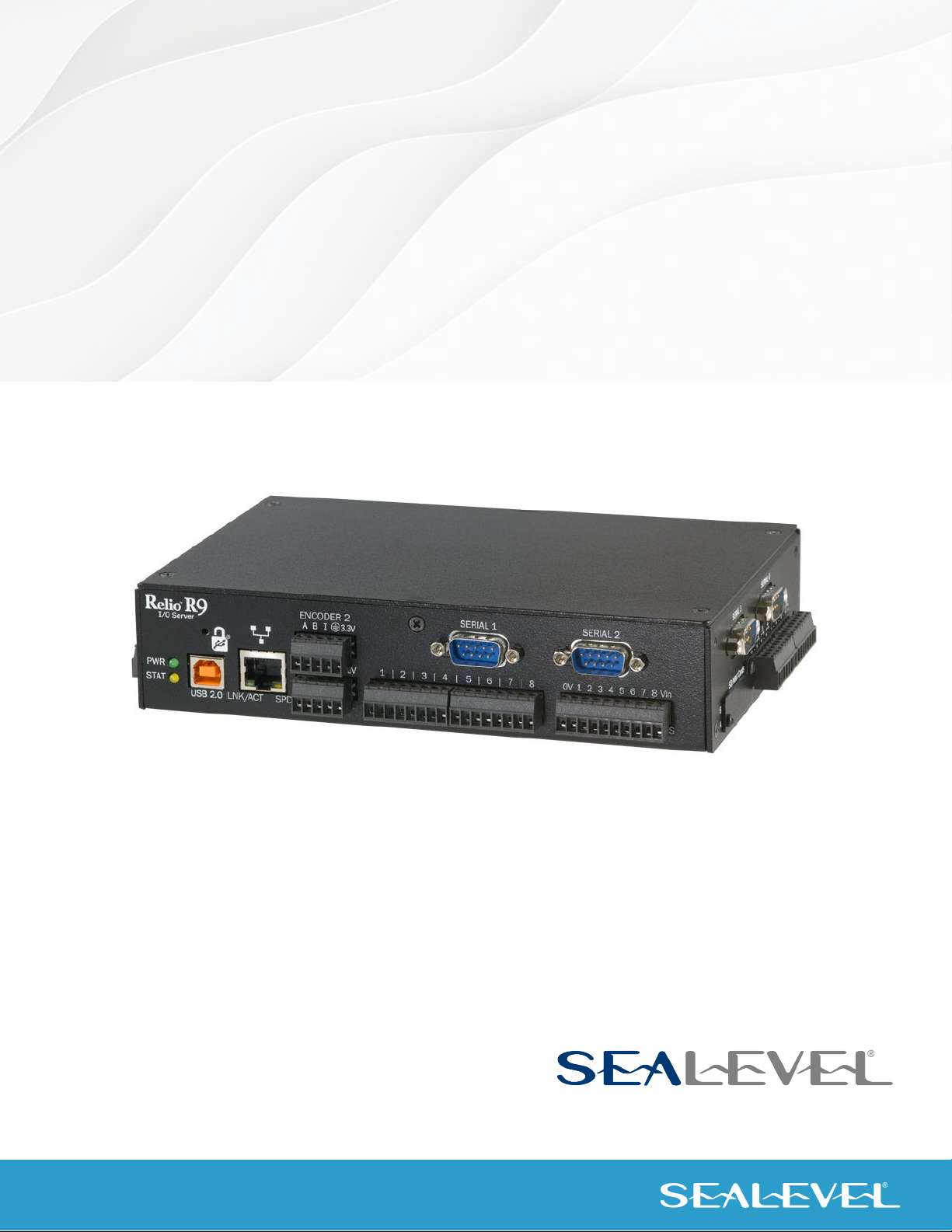
The Relio R9 is an application-ready platform for your next product design. The system is based on the
200MHz Atmel AT91SAM9263 microcontroller boasting a 32-bit ARM® instruction set for maximum
performance. With up to 256MB RAM and 256MB NAND Flash memory, the unmatched I/O features of the
Relio R9 extend the possible uses beyond traditional ARM applications.
To provide the fastest time to market, the Windows CE 6.0 BSP binary and low-level drivers for system I/O
are included. Additionally, the Relio R9 software package is equipped with the Sealevel Talos I/O
Framework, which offers a high-level object-oriented .NET Compact Framework (CF) device interface. This
interface provides an I/O point abstraction layer with built-in support for the specific needs of analog and
digital I/O such as gain control and debouncing.
The Relio R9 is housed in a rugged, small enclosure suitable for mounting almost anywhere and is rated for
a full -40° – +85°C operating temperature range. The Relio R9 is powered from your 7-30VDC source or
select from a variety of Sealevel power supply options.
Features
1. Atmel AT91SAM9263 ARM® Processor
2. Up to 256MB SDRAM and 256MB NAND Flash Memory
3. Dual SD/MMC Expansion Card Slots
4. LCD and Backlight Controller
5. Resistive Touchscreen Controller
6. 10/100 BaseT Ethernet
7. Two USB 2.0 Ports; USB Device Port
8. CAN Bus Interface
9. On-board Serial, Digital, and Analog I/O
10. Compatible with Windows Embedded CE 6.0 and Linux
11. Low Power Requirements
12. Power and Status LED Indicators

5
© Sealevel Systems, Inc. R91001 Manual | SL9211 11/2022
Before You Get Started
What’s Included
The Relio R9 is shipped with the following items. If any of these items are missing or damaged, please
contact Sealevel for replacement.
1. Relio R9 ARM9 Embedded RISC Single Board Computer
2. SD Card with CE runtime image, Talos .NET Framework, application samples, and
documentation
3. Microsoft® Windows® CE 6.0 Core license
Advisory Conventions
Warning
The highest level of importance used to stress a condition where damage could result to the
product, or the user could suffer serious injury.
Important
The middle level of importance used to highlight information that might not seem obvious or a
situation that could cause the product to fail.
Note
The lowest level of importance used to provide background information, additional tips, or other
non-critical facts that will not affect the use of the product.

6
© Sealevel Systems, Inc. R91001 Manual | SL9211 11/2022
Quickstart Kit
The Relio R9-KT QuickStart kit is available, which includes the most common accessories. For applications
with specialized hardware requirements, developers can use the Relio R9 as a platform for application
development while Sealevel designs a customized target system specific to the user’s application
requirements.
The Relio R9-KT includes the following items:
•Relio R9 - ARM9 Embedded RISC Computer
•SD Card with CE runtime image, Talos .NET Framework, application samples, and documentation
•Microsoft Windows CE 6.0 Core License
•TR123 – 100-240VAC to 12VDC @ 2.5A, wall mount power supply
•CA356 - USB Type A to SeaLATCH USB Type B, Device Cable
•CA429 - R9 serial debug cable
•CA246 - CAT5 patch cable, 6' length

7
© Sealevel Systems, Inc. R91001 Manual | SL9211 11/2022
Optional Items
Depending upon your application, you are likely to find one or more of the following items useful with the
Relio R9. All items can be purchased from our website (www.sealevel.com) by calling our sales team at
(864) 843-4343.
Cables
USB Type A to USB Type B, 72" in Length - Device Cable (Item# CA179)
The CA179 is a 72" standard USB device cable that
connects USB peripherals with a Type B connector to
the Type A connector on a host computer. The CA179 is
USB 2.0 compliant and is compatible with USB 1.1 and
1.0 devices.
CAT5 Patch Cable, 7' in Length – Blue (Item# CA246)
Standard 7' CAT5 UTP Patch Cable (RJ45).
R9 Serial Debug Cable, 72" in Length (Item# CA429)
The CA429 is a 72" serial debug cable with a 1x4
connector on one end and a standard DB9F connector
on the other end. The DB9F connector is compatible
with any standard RS-232 DB9M serial port.
Power Supply
100-240VAC to 12VDC @ 2.5A, Wall Mount Power Supply (Item# TR123)
The TR123 is a wall mount (wall wart style) power supply
rated for 100-240VAC input and 12VDC output at 2.5
amps. The 72" cable has tinned leads for use with
products that have screw terminals for input power. The
white line or printing on the insulation indicates positive
polarity.

8
© Sealevel Systems, Inc. R91001 Manual | SL9211 11/2022
Product Overview
Specifications
PROCESSOR
Atmel (AT91SAM9263) — 200MIPS RISC Processor
16KB Data Cache, 16KB Instruction Cache, Write Buffer
Integrated Memory Management Unit (MMU)
MEMORY
Up to 256MB SDRAM (64MB Standard)
256MB NAND Flash
Two SD Memory Card Sockets
LCD CONTROLLER
Supports Passive or Active Displays
16-bit Color in TFT/STN Modes
Resolution Up to 2048 x 2048
TOUCHSCREEN CONTROLLER
Supports 5-wire Resistive Touchscreens
BUS INTERFACES
10/100 BaseT Ethernet
USB Device Port
Two USB 2.0 Ports
CAN Bus
Dedicated RS-485 Expansion
INDUSTRIAL I/O
Four Software Configurable RS-232/422/485 Ports
Eight Optically Isolated Inputs (5 – 24V)
Eight Open-Collector Outputs (5 – 30V; 3 with PWM)
Eight Analog Inputs (12-bit or 16-bit)
Two 32-bit Quadrature Counters
INDICATORS
Dual LED Indicators for Power and Status

9
© Sealevel Systems, Inc. R91001 Manual | SL9211 11/2022
Product Views
RELIO R9 LEFT
RELIO R9 RIGHT
RELIO R9 FRONT

11
© Sealevel Systems, Inc. R91001 Manual | SL9211 11/2022
Technical Description
Memory
The Relio R9 base configuration includes 64MB SDRAM and 256MB NAND Flash. For memory intensive
applications, the board can be ordered preconfigured with up to 256MB SDRAM.
Ethernet
The Relio R9 includes a 10/100 BaseT Ethernet interface accessed via the RJ45 connector located on the
front of the enclosure.
The RJ45 port on the left side of the Relio R9 is a RS-485 Expansion Port (labeled “RS-485 OUT”) and
is NOT an Ethernet port. Damage to Ethernet networking equipment can result if connected to the
RS-485 RJ45 connector.
Pin Signal
1 TX+
2 TX-
3 RX+
4 NC
5 NC
6 RX-
7 NC
8 NC

12
© Sealevel Systems, Inc. R91001 Manual | SL9211 11/2022
USB
The Relio R9 provides two SeaLATCH USB 2.0 host ports, and one SeaLATCH USB device port. The USB
host ports are located on the left side of the enclosure. The USB device port is located on the front of the
enclosure.
Connector: SeaLATCH USB 2.0 Host Port
Manufacturer: Samtec
Description: Standard USB Type A
Mates with: SeaLATCH USB Type A, or Standard USB Type A
Connector: SeaLATCH USB 2.0 Device Port
Manufacturer: Samtec
Description: Standard USB Type B
Mates with: SeaLATCH USB Type B, or Standard USB Type B

13
© Sealevel Systems, Inc. R91001 Manual | SL9211 11/2022
LCD and Touchscreen Controllers
A variety of LCDs can be directly controlled by the Relio R9’s on-board LCD controller. All LCD power and
control signals are available on header connector P2. To access you will need to remove the cover of the
Relio R9.
Connector: P2
Manufacturer: Samtec
Part Number: TFML-125-02-S-D
Description: Locking terminal strip, 50 pos, 0.050” pitch
Mates with: Samtec SFML-125-T2-S-D or Samtec TFMDL-25-T-03.00

14
© Sealevel Systems, Inc. R91001 Manual | SL9211 11/2022

15
© Sealevel Systems, Inc. R91001 Manual | SL9211 11/2022
Serial Debugging
Debug the R9 through the RS-232 debug port. To access you will need to remove the cover of the Relio
R9.
Connector: J6
Manufacturer: Amp/Tyco
Part Number: 9-146278-0-04
Description: Header, 0.100” Polarized 4 pos, pin 3 Removed
Pin RS-232
1 RX
2 GND
3 Key
4 TX

16
© Sealevel Systems, Inc. R91001 Manual | SL9211 11/2022
Serial Communications
Connect to a variety of serial peripherals via the Relio R9’s software configurable RS-232/422/485 ports.
The serial port interfaces are available on DB-9 male connectors. Serial 1 and Serial 2 ports are located on
the front of the enclosure, and Serial 3 and Serial 4 ports are located on the right side of the enclosure.

17
© Sealevel Systems, Inc. R91001 Manual | SL9211 11/2022
Connectors: Serial 1 – Serial 4
Description: DB-9 Male
PIN RS-232 RS-422/485
1 DCD RX+
6 DSR NC
2 RX RX-
7 RTS NC
3 TX TX-
8 CTS NC
4 DTR TX+
9 RI NC
5 GND GND
COM Port Assignments
Serial Port Assignment
RS485 Expansion Port COM1
SERIAL1 COM2
SERIAL2 COM3
SERIAL3 COM4
SERIAL4 COM5

18
© Sealevel Systems, Inc. R91001 Manual | SL9211 11/2022
CAN Bus
Connect directly to a Control Area Network (CAN) bus via the CAN connector on the left side of the
enclosure.
Connector: CAN
Manufacturer: Weco
Part Number: 110-M-111/04
Description: Terminal Block 4 position 3.5mm spacing
Mates with: Weco 110-A-111/04 4 position screw-terminal plug (provided)
Pin Signal
H CAN High
GND
L CAN Low
S Shield

19
© Sealevel Systems, Inc. R91001 Manual | SL9211 11/2022
Optically Isolated Inputs
Interface 8 optically isolated inputs. The non-polarized inputs can range from 5-24VDC and provide 300V
external isolation. Connection is made at on the front of the enclosure.

20
© Sealevel Systems, Inc. R91001 Manual | SL9211 11/2022
Connector: OPTO INPUTS
Manufacturer: Weco
Part Number: (2) 110-M-111/08
Description: (2) Terminal Block 8 position 3.5mm spacing
Mates with: (2) Weco 110-A-111/08 8 position screw-terminal plugs (provided)
Pin Signal
1
Input 1A
Input 1B
2
Input 2A
Input 2B
3
Input 3A
Input 3B
4
Input 4A
Input 4B
5
Input 5A
Input 5B
6
Input 6A
Input 6B
7
Input 7A
Input 7B
8
Input 8A
Input 8B
This manual suits for next models
1
Table of contents
Other SeaLevel Desktop manuals