INSTRUCTIONS FOR:
FUSE FINDER KIT
Model EFF7
Thank you for purchasing a Sealey product. Manufactured to a high standard this product will, if used according to these instructions and properly maintained, give you years of trouble free performance.
IMPORTANT: PLEASE READ THESE INSTRUCTIONS CAREFULLY. NOTE THE SAFE OPERATIONAL REQUIREMENTS, WARNINGS AND CAUTIONS. USE THIS PRODUCT
CORRECTLY AND WITH CARE FOR THE PURPOSE FOR WHICH IT IS INTENDED. FAILURE TO DO SO MAY CAUSE DAMAGE AND/OR PERSONAL INJURY AND WILL
INVALIDATE THE WARRANTY. PLEASE KEEP INSTRUCTIONS SAFE FOR FUTURE USE.
C
C
H
H
E
E
C
C
K
K
E
E
L
L
E
E
C
C
1.1. ELECTRICAL SAFETY
p WARNING! It is the responsibility of the owner and the operator to read, understand and comply with the following:
You must check all electrical products, before use, to ensure that they are safe. You must inspect power cables, plugs, sockets and any other
connectors for wear or damage. You must ensure that the risk of electric shock is minimised by the installation of appropriate safety devices.
A Residual Current Circuit Breaker (RCCB) should be incorporated in the main distribution board. We also recommend that a Residual Current
Device (RCD) is used. It is particularly important to use an RCD with portable products that are plugged into a supply which is not protected by
an RCCB. If in any doubt consult a qualified electrician. You may obtain a Residual Current Device by contacting your Sealey dealer.
You must also read and understand the following instructions concerning electrical safety.
1.1.1. The Electricity at Work Act 1989 requires all portable electrical appliances, if used on business premises, to be tested by a qualified
electrician, using a Portable Appliance Tester (PAT), at least once a year.
1.1.2. The Health & Safety at Work Act 1974 makes owners of electrical appliances responsible for the safe condition of those appliances and
the safety of the appliance operators. If in any doubt about electrical safety, contact a qualified electrician.
1.1.3. Ensure that the insulation on all cables and on the appliance is safe before connecting it to the power supply. See 1.1.1. and 1.1.2. and use
a Portable Appliance Tester.
1.1.4. Ensure that cables are always protected against short circuit and overload.
1.1.5. Regularly inspect power supply cables and plugs for wear or damage and check all
connections to ensure that none is loose.
1.1.6. Important: Ensure that the voltage marked on the appliance matches the power supply
to be used and that the plug is fitted with the correct fuse - see fuse rating at right.
1.1.7. DO NOT pull or carry the appliance by the power cable.
1.1.8. DO NOT pull the plug from the socket by the cable.
1.1.9. DO NOT use worn or damaged cables, plugs or connectors. Immediately have any faulty
item repaired or replaced by a qualified electrician. When a BS 1363/A UK 3 pin plug is
damaged, cut the cable just above the plug and dispose of the plug safely.
Fit a new plug according to the following instructions (UK only).
a) Connect the GREEN/YELLOW earth wire to the earth terminal E.
b) Connect the BROWN live wire to the live terminal L.
c) Connect the BLUE neutral wire to the neutral terminal N.
d) After wiring, check that there are no bare wires, that all wires have been correctly connected, that the cable outer insulation
extends beyond the cable restraint and that the restraint is tight.
1.2. OPERATIONAL SAFETY
1.2.1. The Fuse Finder Kit is for use on 230V 50Hz circuits only.
1.2.2. The kit is intended for use by suitably qualified electricians familiar with electrical supply systems.
1.2.3. When using the test lead adaptor to connect the transmitter to bare wires, light fittings etc. take extreme care and, if possible, switch off the
power whilst connections are being made.
1.2.4. Use only in dry conditions, where there is no condensation.
1. SAFETY INSTRUCTIONS
2. INTRODUCTION
3. BATTERY
FUSE RATING 13 AMP
Blue
Neutral
Wire
Yellow & Green
Earth Wire
Cable
Restraint
Brown
Live
Wire
2.1. DESCRIPTION
The EFF7 Fuse Finder Kit enables the fuse or breaker which protects the circuit in question to be easily located. The transmitter is plugged into, or
connected by clip/probe test leads to, the circuit (which must be live) into which it then injects a signal. This signal is detected by the receiver when
passed over the circuit fuse or breaker.
2.2. CONTENT
Check the contents of the kit against the list below. If any item is missing,
or damaged, contact your Sealey dealer immediately.
1Receiver 4 Transmitter
2 Test Lead + Crocodile Clips 5 Test Probes
313A Adaptor Lead 6Case
3.1. Remove the rear cover of the receiver (fig. 1.1), by removing
the screw and sliding the cover down, to reveal the battery
compartment. Install a 9V alkaline battery (not supplied) and
replace cover and screw. Battery type PP3/MN1604/6F22.
Note: The transmitter is powered by the 230V supply and does not require a battery.
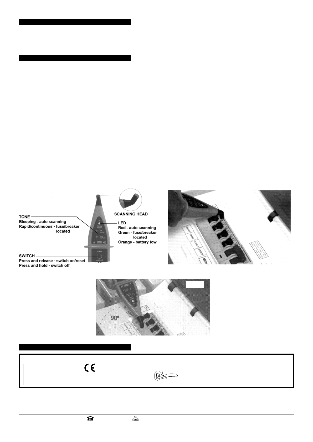
3.2. When the receiver is in use and the battery is low the scanning function LED (see fig. 2) will show orange and the beeping tone will have
a longer than normal duration - battery is down to approximately 20% of full capacity and will require replacement shortly.
fig. 1
EFF7 - 1 - 110702