4.1. Unpack the product and check contents against the parts listed below.
If there is anything damaged or missing contact your supplier immediately.
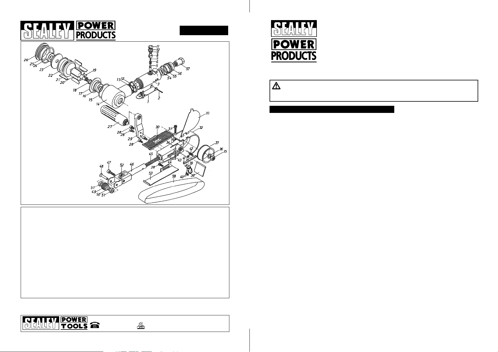
Contents: SA356 Belt Sander, Sanding Belt and Hex. Key.
pWARNING! Ensure that you have read and
understood and then apply the safety instructions in Section 1.
4.2. Loosening the slider bolt on the underside of the sander allows the
slider to move closer to/further away from the idle pulley, tightening the belt
to suit the job in hand. After adjustment retighten the slider bolt.
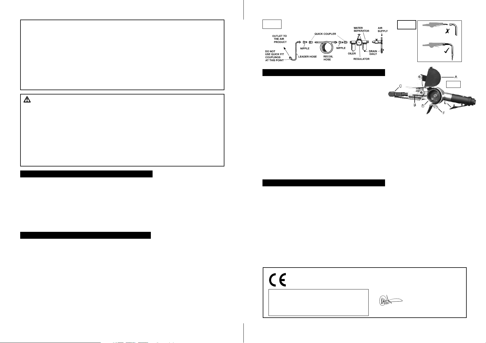
4.3. Once connected to the air supply the sander is started by squeezing the trigger (E).
4.4. To remove and replace the sanding belt:
4.4.1 Ensure air-line is detached from the unit.
4.4.2 Release metal clip (F) retaining the pulley cover (A).
4.4.3 Press and hold spring-loaded latch (B), whilst pulling the idle pulley (C) inwards, towards the
drive pulley (D). once compressed, release the latch (B), ensuring it is engaged.
4.4.4 Replace/fit new sanding belt, close the pulley cover and release the spring loaded latch (B), being
careful of fingers or lose items.
4.5. The tracking of the belt can be altered by the adjusting bolt closest to the idle pulley on the opposite side of fig.1.
2. INTRODUCTION AND SPECIFICATIONS
3.1. AIR SUPPLY
Recommended hook-up procedure is shown in fig 1.
3.1.1 Ensure the sander air valve (or throttle) is in the "off" position before connecting to the air supply.
3.1.2 You will require an air pressure between 70-90psi, and an air flow according to the specification above.
3.1.3 pWARNING! Ensure the air supply is clean and does not exceed 90 psi while operating the sander.
Too high an air pressure and unclean air will shorten the product life due to excessive wear, and may be
dangerous causing damage and/or personal injury.
3.1.4 Drain the air tank daily. Water in the air line will damage the sander and invalidate your warranty.
3.1.5 Clean air inlet filter weekly.
3.1.6 Line pressure should be increased to compensate for unusually long air hoses (over 8 metres).
The minimum hose diameter should be 1/4 I.D. and fittings must have the same inside dimensions.
3.1.7 Keep hose away from heat, oil and sharp edges. Check hoses for wear, and make certain that all
connections are secure.
3.2 COUPLINGS
Vibration may cause failure if a quick change coupling is connected directly to the air sander. To
overcome this, connect a leader hose to the sander. Aquick change coupling may then be used to
connect the leader hose to the air line recoil hose. See fig 1 & 2 (next page).
pWARNING! Disconnect sander from air supply before changing accessories, servicing or performing
maintenance. Replace or repair damaged parts. Use genuine parts only. unauthorised parts may be
dangerous and will invalidate the warranty.
5.1. If the system does not have an oiler, lubricate the air sander daily with a few drops of good grade air tool
oil such as Sealey ATO/500 or ATO1000, dripped into the air inlet (8) before use.
5.2. Clean the sander after use and change belts when required.
5.3. Loss of power or erratic action may be due to the following:
a) Excessive drain on the air line. Moisture or restriction in the air pipe. Incorrect size or type of hose
connectors. To remedy check the air supply and follow instructions in chapter 3.
b) Grit or gum deposits in the sander may also reduce performance. If your model has an air strainer
(located in the area of the air inlet), remove the strainer and clean it. Flush the sander out with gum
solvent oil or an equal mixture of SAE No 10 oil and kerosene. Allow to dry before use.
If you continue to experience problems, contact your local Sealey service agent.
5.4. For a full service contact your local Sealey service agent.
5.5. When not in use, disconnect from air supply, clean sander and store in a safe, dry, childproof location.
3. PREPARING SANDER FOR USE
4. OPERATING INSTRUCTIONS
5. MAINTENANCE
1.2. LEAD PAINT WARNING!
Paint once contained lead as a traditional ingredient. Contact with the dust from the removal of such
paint is toxic and must therefore be avoided. The following action must be taken before using the
sander on a surface that you suspect may contain lead paint.
1. User must determine potential hazard relating to age of paint to be removed.
(Modern paints do not have lead content).
2. DANGER! Keep all persons and pets away from the working area. The following persons are
particularly vulnerable to the effects of lead paint dust: Expectant women, babies and children.
3. We recommend personal protection by using the following safety items:
a) Paint Spray Respirator (Our ref SSP16EN)
b) PE Coated Hooded Coverall (Our ref SSP266). c) Latex Gloves (Our ref SSP24).
4. Take adequate measures to contain the paint dust, flakes and scrapings.
5. Continue to wear safety equipment as in (3) above and thoroughly clean all areas when task is
complete. Ensure paint waste is disposed of in sealed bags or containers.
fig 1
We, the sole importer into the UK, declare that the product listed here is in conformity with the
following EEC standards and directives. The construction file for this product is held by the
Manufacturer and may be inspected, by a national authority, upon request to Jack Sealey Ltd.
For Jack Sealey Ltd. Sole importer into the UK
of Sealey Power Products.
Air Operated 30mm Belt Sander
Model SA356
98/37/EC Machinery Directive
93/68/EEC Marking Directive
21st Oct 2004
Declaration of Conformity
Signed by Mark Sweetman
fig 2
Aluminium housing with articulated sanding arm and integral regulator. Features belt tracking control, heavy-duty
nose roller and left- or right-hand mounting for side handle. Suitable for sanding otherwise inaccessible areas
such as around door-shuts. Wide belt makes tool suitable for welding work too. Spare belts available from stock.
Specification
Belt . . . . . . . . . . . . . .30 x 540mm
Air Pressure . . . . . . . . . . . . .90psi
Air Consumption . . . . . . . . .20cfm
Air Inlet . . . . . . . . . . . . . . .¼BSP
Weight . . . . . . . . . . . . . . . . .2.1kg
Sound Level . . . . . . . . . . .85dB.A
Vibration level . . . . . . . . . .0.3m/s²
Uncertainty Value . . . . . . . 0.12m/s²
fig 1
SA356 - 1 - 211004
Risk of Hand Arm Vibration Injury
Air Operated 30mm Belt Sander SA356 when operated in accordance with these instructions and tested in
accordance with EN 28662-2: 1994 results in the following vibration emission declared in accordance with
BS EN12096: 1996.
Measured vibration emission value: . . . . . . . . . . .0.3m/s2
Uncertainty: . . . . . . . . . . . . . . . . . . . . . . . . . . . . .0.12m/s2
These values are suitable for comparison with emission levels of other tools that have been subject to
the same test.
This tool may cause hand-arm vibration syndrome if its use is inadequately managed.
Recommended Measures to reduce risk of hand-arm vibration syndrome:
This item represents a low Hand Arm Vibration risk to users. The calculated minimum usage period exceeds 8
hours. We recommend appropriate safety equipment is utilised and regular breaks for the operator are
employed to reduce any residual risk of fatigue or repetitive strain injury.