INSTRUCTIONS FOR:
CAR PORT SHELTER 3 X 5.1 X 2.4M
MODEL NO: CPS01
IMPORTANT: PLEASE READ THESE INSTRUCTIONS CAREFULLY. NOTE THE SAFE OPERATIONAL REQUIREMENTS, WARNINGS & CAUTIONS. USE THE PRODUCT
CORRECTLY AND WITH CARE FOR THE PURPOSE FOR WHICH IT IS INTENDED. FAILURE TO DO SO MAY CAUSE DAMAGE AND/OR PERSONAL INJURY AND WILL
INVALIDATE THE WARRANTY. KEEP THESE INSTRUCTIONS SAFE FOR FUTURE USE.
Thank you for purchasing a Sealey product. Manufactured to a high standard, this product will, if used according to these
instructions, and properly maintained, give you years of trouble free performance.
1. SAFETY
Refer to
instruction
manual
Wear eye
protection
Wear
protective
gloves
7 This is a temporary structure and is not recommended as a permanent structure.
3Choose your shelter’s location carefully. Check for overhead utility lines, branches, etc. DO NOT install near rooves or other structures that
may shed snow, ice or excessive run-off onto your shelter. Keep away from electrical wires!
3 Have an overview of all parts before attempting installation. Make sure all components are available.
7 DO NOT use this product in environments for which it is not intended (i.e. extreme cold, high winds, extreme heat, heavy rainfall, etc).
3 Always wear safety glasses when assembling this product. Wear gloves when working with tubing to prevent cuts or abrasions.
WARNING! Anchors must be used with alI shelters. Covers should NOT be installed untiI it has been properly anchored to the ground.
3Proper anchoring and keeping cover tight and free of snow and debris, is the responsibility of the consumer. Damages caused by improper
anchoring are not covered under warranty.
WARNING! Keep all flame and heat sources away from the shelter fabric. The fabric will burn if left in continuous contact with a flame
source.
7 DO NOT use open flames or cooking or heating devices inside or in close proximity to the product,including all types of stoves, gas
heaters, gas lanterns, citronella torches, mosquito coils, etc.
WARNING! In order to reduce risk of burning and avoid damage, DO NOT:
- cook, smoke, refuel or use any open flame devices in or around the shelter.
- store flammable liquids (gasoline, kerosene, propane, etc.) in the shelter.
- operate gas powered equipment in or around the shelter.
3Keep open flames a safe distance away from the shelter.
7DO NOT use hard-edged tools or instruments, such as rakes or shovels, to remove snow. These can cause punctures to the cover.
7NEVER start the engine of any vehicle or machine inside a closed shelter. Ensure that there is adequate ventilation for starting engines
and for any work with paints, cleaners, etc.
7DO NOT use bleach, alkaline or harsh detergents for cleaning. Doing so will damage the polycarbonate material. Soap and warm water
are recommended.
3This temporary shelter is intended to offer protection from damages caused by the sun, light rain, light snow, tree sap, bird and animal
excrements. DO NOT use it to shield goods from high winds, heavy snow or ice storms. Only use it for its intended use.
2. INTRODUCTION
3. SPECIFICATION
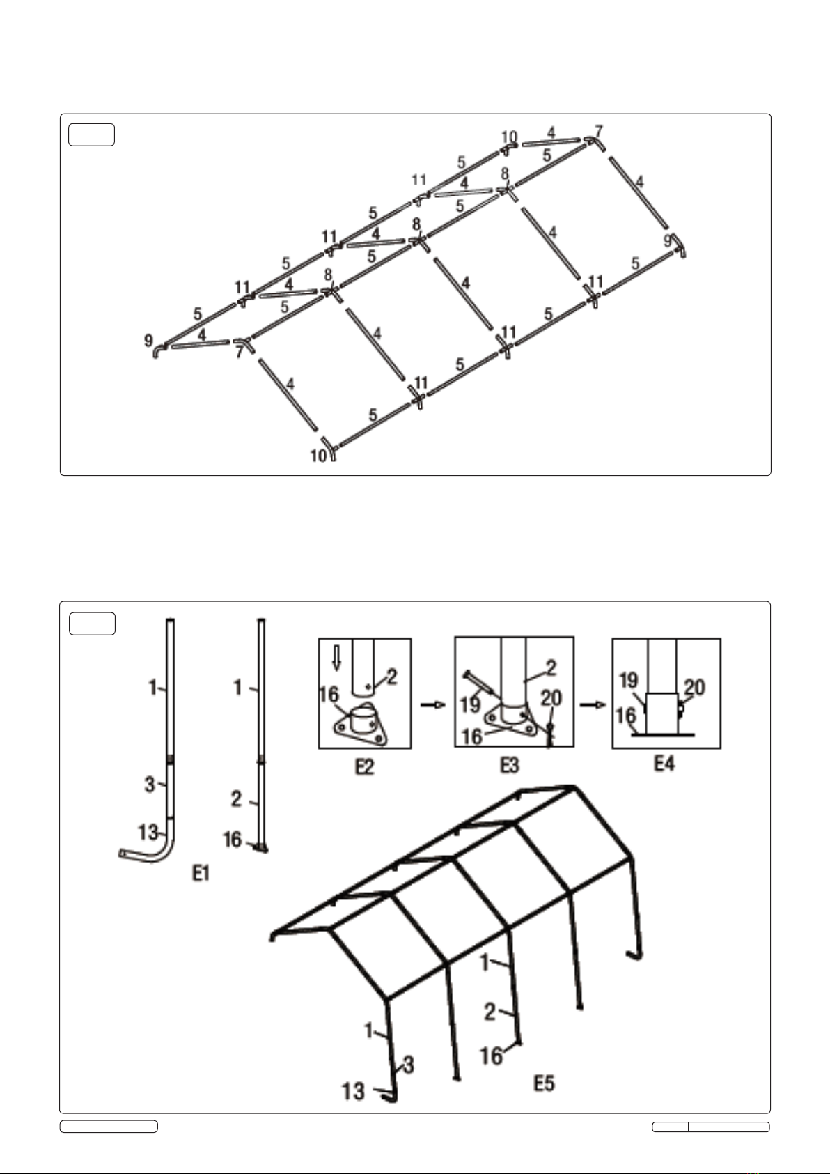
4. ASSEMBLY
Allows for extra space quickly when required, a garage for cars, storage for boats, materials and machinery. Constructed of a Thermoset
powder coated nished steel frame work, which is strong and rust resistant with a heavy-duty tarpaulin made of a PE (polyethylene) material
of a 3 layer construction with rip stop to help prevent tears. UV resistant and offers long life and good protection to stored items. Included stake
pegs secure the shelter against strong winds, a dirt skirt on both sides further protect against crosswinds. A wide opening double zip door, which
can be rolled up out of the way, provides easy access.
Model No: ......................CPS01
Overall Size: .....................3040 x 5180 x 2430mm
4.1. Assembly Preparation
4.1.1. Place all parts from the packaging box in a cleared area and arrange them on the ground in front of you.
4.1.2. Remove all packaging materials and place them back in the box. DO NOT dispose of the packaging materials until assembly is
complete.
Check for completeness and transport damages.
WARNING! DO NOT place the product under trees from which hard fruit such as apples, walnuts or heavy pine cones, etc., may fall.
4.1.3. Keep children away during assembly. This product contains small parts which can be swallowed by children.
4.1.4. DO NOT attempt to assemble the product if any parts are missing.
4.1.5. At least 3 people are needed to complete the assembly as some of the steps require heavy lifting.
WARNING! DO NOT leave the shelter unattended during assembly. Otherwise, personal injury or damage to the shelter may occur!
CPS01 Issue: 1 - 19/12/14
Original Language Version
© Jack Sealey Limited