Sealy RS131.V3 User manual

INSTRUCTIONS FOR
ROADSTART EMERGENCY POWER PACKS
MODEL NOS: RS131.V3, RS132
Thank you for purchasing a Sealey product. Manufactured to a high standard, this product will, if used according to these
instructions, and properly maintained, give you years of trouble free performance.
IMPORTANT: PLEASE READ THESE INSTRUCTIONS CAREFULLY. NOTE THE SAFE OPERATIONAL REQUIREMENTS, WARNINGS & CAUTIONS. USE
THE PRODUCT CORRECTLY AND WITH CARE FOR THE PURPOSE FOR WHICH IT IS INTENDED. FAILURE TO DO SO MAY CAUSE DAMAGE AND/OR
PERSONAL INJURY AND WILL INVALIDATE THE WARRANTY. KEEP THESE INSTRUCTIONS SAFE FOR FUTURE USE.
1. SAFETY
IMPORTANT: To reduce the risk of a battery explosion, follow these instructions and those published by the battery manufacturer and the
manufacturer of any equipment you intend to use in the vicinity of the battery. Remember to review warning marks on all products and on
engines.
1.1. PERSONAL PRECAUTIONS
Ensure there is another person within hearing range, or close enough to come to your aid should a problem arise, when working
near a lead-acid battery.
Have fresh water and soap nearby in case battery acid contacts skin, clothing or eyes.
Wear safety eye protection and protective clothing. Avoid touching eyes while working with a battery.
Washimmediatelywithsoapandwaterifbatteryacidcontactsskinorclothing.Ifacidenterseye,usheyeimmediatelywithcool,
clean running water for at least 15 minutes and seek immediate medical attention.
Remove personal metallic items such as rings, bracelets, necklaces and watches. A lead-acid battery can produce a short-circuit
current high enough to weld a ring or the like to metal, which may cause severe burns.
1.2. IMPORTANT SAFETY INSTRUCTIONS
Familiarise yourself with the applications, limitations and potential hazards of the RoadStart.
Keep the unit in good working order and condition. Replace damaged parts immediately.
Use only recommended parts. To use unapproved parts may be dangerous and will invalidate your warranty.
TheRoadStartmustonlybeopenedandcheckedbyqualiedservicepersonnel.DO NOT disassemble the unit for any reason.
Keep children and unauthorised persons away from the work area.
Keep work area clean and tidy and free from unrelated materials. Ensure that there is adequate lighting.
IftheRoadStartreceivesasharpknockorblow,itmustbecheckedbyaqualiedserviceagentbeforebeingused.
When not in use re-charge every two months.
DO NOTsmokeorallowaspark,orameinthevicinityofthebatteryorengine.
DO NOT drop any metal item onto the battery as it may spark or short circuit the battery, which could cause an explosion.
DO NOT use RoadStart to recharge dry cell batteries that are commonly used with home appliances. These batteries may explode and
cause personal injury and damage to property.
DO NOT charge or boost a frozen battery.
DO NOT use attachments other than those recommended. To do so may risk damage to the unit and other equipment and possible
personal injury.
DO NOT pull or carry the unit by its cables and do not pull the negative and positive clamps from the battery terminals.
DO NOToperateinvicinityofammableliquidsorgases.
DO NOT recharge the unit with plugs, cables or attachments that are damaged. Replace such items immediately.
DO NOT use this product to perform a task for which it is not designed.
DO NOT store the unit in damp or wet locations or where the temperature may exceed 50°C.
DO NOT submerge the unit in water.
Refer to
Instruction
Manual
Warning:
Explosive
Material
Warning:
Corrosive
substance
Wear eye
Protection
RS131.V3 RS132 | Issue 4(I) 21/05/15
Original Language Version
© Jack Sealey Limited
IMPORTANT WARRANTY INFORMATION: KEEP YOUR ROADSTART HEALTHY
Read and understand the general safety and operating instructions before use. The following information is intended to help you
keep the product in top working order.
NOTE – The battery in this unit is a consumable item and its ability to accept charge will reduce over time. We will warranty it
against mechanical and electrical defect for a period of one year - this does not cover fair wear and tear.
If the battery is not properly charged before first use, or regularly conditioned, its capacity will diminish. Under these circumstances we will
not replace the battery even if it is less than one year old.
You can help prolong the lifecycle of the battery by following a few simple guidelines.
• Plug in your new Roadstart to the mains transformer and make an INITIAL charge lasting 38 hours.
• Ensure the unit is fully charged before storage.
• DO NOT leave the Roadstart for longer than 2 months without putting it on charge.
• DO NOT attempt to start a vehicle when the Roadstart battery voltage is reduced to less than 7Volts.
• DO NOT drop or roughly handle the Roadstart – this will break or disjoin the battery terminals rendering the battery useless and the
warranty void.
• DO NOT use any other charger, other than the one supplied, to recharge the battery.
DO NOTusewhilstundertheinuenceofdrugs,alcoholorintoxicatingmedication.
DO NOT leave the unit in a totally discharged state for an extended period of time as this may result in permanent damage.
DO NOT cross-connect the power leads from the RoadStart to the battery. Ensure that positive is to positive and negative is to
negative. Observe polarity indicator during connection.
Ensure that the unit is fully charged before storage.
1.3. ELECTRICAL SAFETY (with respect to mains chargers)
RWARNING! It is the user’s responsibility to check the following:
You must check the AC adaptor to ensure that it is safe before using. You must inspect the power supply lead, plugs and all
electrical connections for wear and damage. You must ensure the risk of electric shock is minimised by the installation of
appropriate safety devices. An RCCB (Residual Current Circuit Breaker) should be incorporated in the main distribution board.
We recommend that an RCD (Residual Current Device) is used with all electrical products. It is particularly important to
useanRCDwithportableproductsthatplugintoanelectricalsupplynotprotectedbyanRCCB.Ifindoubtconsultaqualied
electrician. You can obtain a Residual Current Device through your Sealey dealer. You must read and understand instructions
concerning electrical safety.
1.3.1.The Electricity At Work Act 1989 requires all portable electrical appliances, if used on business premises, to be tested
byaqualiedperson,usingaPortableApplianceTester(PAT),atleastonceayear.
1.3.2.The Health & Safety at Work Act 1974 makes owners of electrical appliances responsible for the safe condition of the appliance and the
safetyoftheapplianceoperator.Ifinanydoubtaboutelectricalsafety,contactaqualiedelectrician.
1.3.3.DO ensure that the insulation on all cables and the product itself is safe before connecting to the mains power supply.
1.3.4.DO ensure that cables are always protected against short circuit and overload.
1.3.5.DO regularly inspect power supply, leads, plugs for wear and damage and power connections to ensure that none is loose.
1.3.6.DO checkproductvoltageisthesameaspowersupplytobeusedandcheckthatallfusedplugsarettedwiththecorrectcapacity
fuses.
2. INTRODUCTION
Composite case with moulded rubber protection, integral battery cable storage and carry handle. LED battery condition, polarity check and
chargeindicators.Featuresindependenton/offswitchwhichallowsthepositiveclamptobeconnectedwithouttheriskofsparking.Alsotted
withanintegralKryptonworklightforuseatnight.Fittedwith12Voltpowersocketthatwillacceptany12Voltdevicettedwithacigarette
lighter type plug. Supplied with mains charger and double plug adaptor for in-car charging. RS132 has integral air compressor with pressure
gauge for accurately topping/pumping up tyres etc.
3. SPECIFICATION
Model: ................................................... RS131.V3 & RS132
Cold cranking amps: ......................................................200A
Peak amps: ....................................................................900A
Voltage: ............................................................................12V
Auxillary output: ...............................................................12V
Cable and clamp length: ............................................ 780mm
Built in compressor (RS132 only):.................................... yes
Max pressure: ............................................................... 80psi
Weight:...............................(RS131.V3) 5.9kg (RS132) 6.5kg
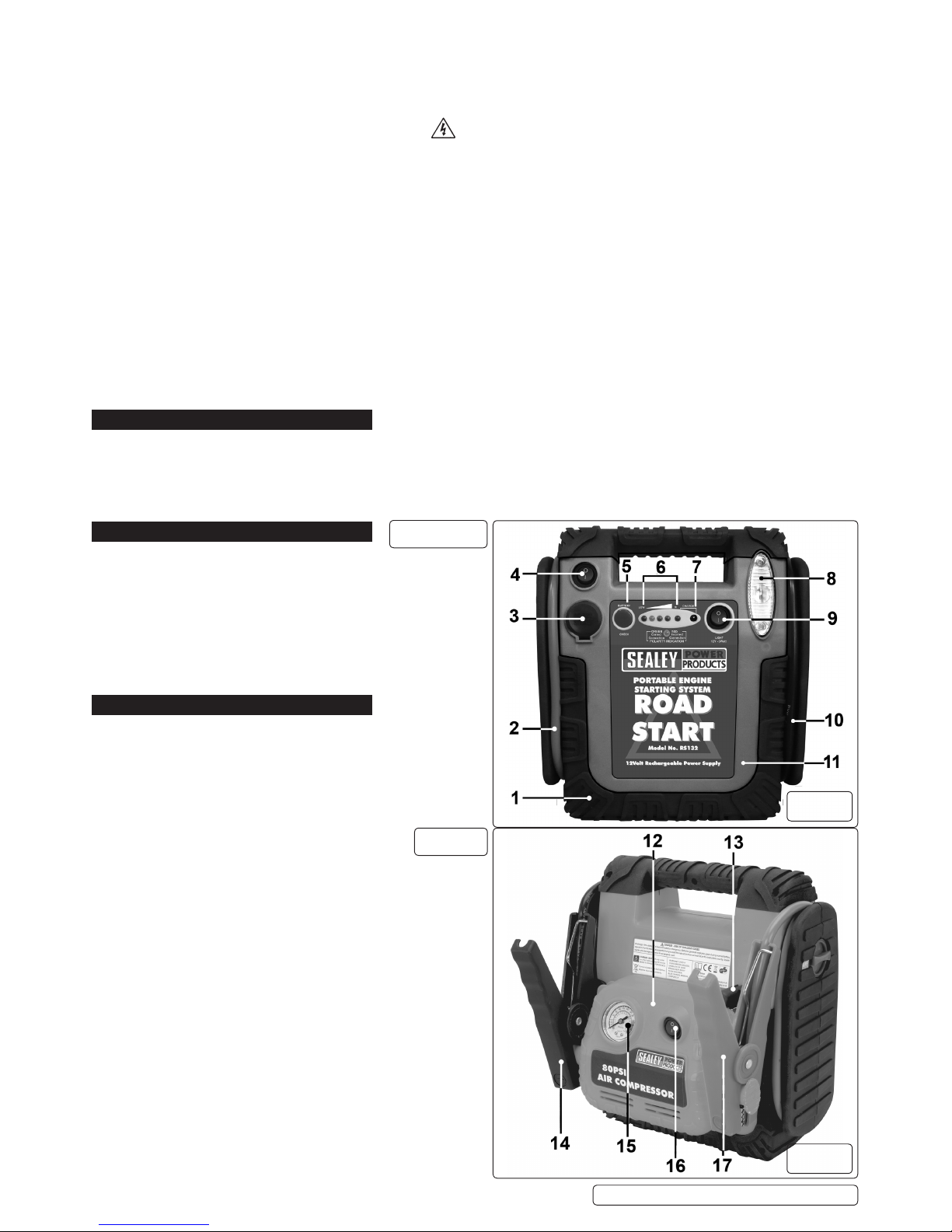
4. PRODUCT FEATURES
(Keytogs.1,2,3&4)
1) MOULDED RUBBER PROTECTION
2) HEAVY DUTY COPPER CABLE (POSITIVE+)
3) 12VDC OUTPUT SOCKET
4) 12VDC OUTPUT ON/OFF SWITCH
5) BATTERY CHECK BUTTON
6) LED CHARGE STATE INDICATORS
7) AC CHARGING SOCKET
8) KRYPTON WORK LIGHT
9) WORK LIGHT SWITCH
10) HEAVY DUTY COPPER CABLE (NEGATIVE+)
11) COMPOSITE CASING
12) COMPRESSOR CASING (RS132 only)
13) VALVE CONNECTOR (RS132 only)
14) NEGATIVE (-) BATTERY CLAMP (BLACK)
15) COMPRESSOR PRESSURE GAUGE (RS132 only)
16) COMPRESSOR ON/OFF SWITCH (RS132 only)
17)POSITIVE (+) BATTERY CLAMP (RED)
18)POSITIVE (+) BATTERY CLAMP SAFETY SWITCH
RS131.V3
RS132
g.1
g.2
RS131.V3 RS132 | Issue 4(I) 21/05/15
Original Language Version
© Jack Sealey Limited

WARNING! YOU MUST FOLLOW THE SAFETY INSTRUCTIONS
5. CHARGING INSTRUCTIONS
5.1. INTIAL CHARGING OF THE ROADSTART UNIT
NOTE: This product may arrive partially charged. The unit must be fully charged immediately after purchase and before using for
thersttime.
5.1.1. TheunitshouldbechargedusingtheACchargersupplied(seeg.6)foraperiodof38hours.Subsequentchargesusing
the AC Charger should be for a period of 34 to 36 hours. Never charge the unit for more than 40 hours.
5.1.2. The unit may also be subsequently charged from a 12V DC cigarette socket in a vehicle for a period of 12 to 14 hours.
RWARNING! Do not overcharge this unit as this could cause damage to the battery and invalidate the warranty.
5.1.3. To prevent overcharging the user is required to monitor the progress of the charge by pressing the Battery Check Button at regular
intervals(seeg.5).
5.2. READINGTHELEDPOWERLEVELINDICATORSSeeg.5
5.2.1. The charge level of the unit during use can be seen at any time by pressing the Battery Check Button and noting which power level
lights that are illuminated.
5.2.2. When both green LEDs are illuminated the unit is fully charged and is ready to be used for starting a vehicle.
5.2.3. If only one green LED is illuminated the unit is partially discharged but can be used to operate most 12 volt accessories.
5.2.4. If only the yellow LED is illuminated the power level is low and only a short operating time remains. The unit should be recharged
as soon as practical.
5.2.5. If there is only one red light illuminated the unit cannot be used and must be recharged immediately.
5.2.6. To gain an accurate reading of battery status, press the Battery Check Button.
5.3. RECHARGING WITH THE AC CHARGING ADAPTOR
Note:Onlychargewiththeadaptorsuppliedwithyourspecicmodel.Chargingadaptorsarenotinterchangeable.
5.3.1. Ensurethebatteryclampsaresecurelyattachedtotheclampingbarsontheunitasshownings.2&4.Turnthesafetyswitchon
thesideoftheunittoOFFasshownings.3&4.
5.3.2. PlugtheACchargercableintothechargingsocketonthefrontcontrolpanel.Seeg.5.
5.3.3. Plugthechargeritselfintoany230VoltACwalloutlet.Thered‘Charging’indicatorwillilluminate,seeg.5.Chargingwillnow
commence but the charge level must be regularly monitored to prevent overcharging. Monitor the charge by pressing the
Battery Check Button.
5.3.4. Charging a unit with a very low charge (i.e.showing 1 red LED only) should take 34 to 36 hours. When the two green charge
g.3 g.4
g.5 g.6
RS131.V3 RS132 | Issue 4(I) 21/05/15
Original Language Version
© Jack Sealey Limited
RS131.V3
RS132

indicators are illuminated the unit is fully charged and the charger should be disconnected from the unit and from the AC supply.
5.4. RECHARGING WITH THE DC CHARGING CABLE
VIMPORTANT: Always ensure that the vehicle voltage matches the voltage of the Roadstart unit. Do not operate any of the units
functions during the charging process.
5.4.1. Ensurethebatteryclampsaresecurelyattachedtotheclampingbarsontheunitasshownings.2&4.Turnthesafetyswitchon
thesideoftheunittoOFFasshownings.3&4.
5.4.2. WiththevehicleenginerunningplugtheDCchargingcableintothechargingsocketontheunit(seeg.5)andthentheother
end into the vehicle cigarette lighter socket. The unit will be charged by the alternator.
5.4.3. Thered‘Charging’indicatorwillilluminate,seeg.5.Chargingwillnowcommencebutthechargelevelmustberegularly
monitored to prevent overcharging. Charging a battery in this way with a very low charge (showing 1 red LED only) should take
12 to 14 hours.
5.4.4. When the two green charge indicators are illuminated, when the Battery Check Button is pressed, the unit is fully charged and the
charger cable should be disconnected from the unit and from the vehicle.
Do not leave a discharged unit connected to the vehicle if the engine is not running. To do so will discharge the vehicle battery.
6. OPERATION
6.1. PREPARATION AND PRECAUTIONS
RWARNING! ENSURE THAT THE ROADSTART AND VEHICLE VOLTAGES ARE THE SAME.
6.1.1. Apply the vehicle hand brake and place in neutral gear (or “Park” if automatic transmission).
Turn ignition and electrical accessories off. NOTE: Some vehicle ignition systems must be turned to “Accessory” to activate the
cigarette lighter socket.
6.1.2. Use in a well ventilated area and wear protective eye shields and clothing.
NOTE: A defective battery may not accept a charge from the portable power source.
RWARNING! Do not allow the red and black clamps to touch each other. Ensure that the correct clamps are placed on the
correct battery terminals. Observe the Polarity Indication on the control panel. If the dual colour LED is green the connection is
correct. If the LED is red do not proceed until the connections are correct.
6.2. BOOSTING A VEHICLE BATTERY
6.2.1. Plugoneendofthe12VDCplugtopluglead(seeg.8).intothesocketontheRoadStartunit.
6.2.2. Plug the other end into the vehicle cigarette lighter socket. Allow the vehicle battery to charge for thirty minutes.
6.2.3. Remove the charging lead and start the vehicle.
6.2.4. Press the Battery Check Button to assess the state of charge of the unit and recharge if required.
6.3. EMERGENCY JUMP STARTING
RWARNING! Vehicles equipped with on board computers may be affected if the engine battery is jump started. Read your vehicle
owner’s manual before attempting to start the vehicle to determine if external starting assistance can be used.
Failure to follow these instructions may cause damage or explosion.
NOTE: For optimum performance, the unit should not be stored below 10°C when using the unit as a jump starter.
VIMPORTANT: The unit will only jump start a vehicle if the vehicle battery voltage is greater than 7V. If the battery is delivering less
than 7V, refer to Section 6.2 and follow the instructions to boost the vehicle battery.
6.3.1. Turn off the vehicle ignition.
6.3.2. Determine whether your vehicle uses a negative or a positive earthing system. If you are unsure refer to the owners manual
provided with the vehicle.
6.3.3. Negative earthing - The negative battery terminal is grounded to the vehicle’s chassis. Most vehicles use this system.
6.3.4. Positive earthing - The positive battery terminal is grounded to the vehicle’s chassis.
6.4. CONNECTIONS FOR NEGATIVE EARTHED VEHICLE
6.4.1. Attach the RED (positive +) clamp to the positive terminal of the battery.
Note: On vehicles with multiple batteries connect positive clamp to positive battery terminal which is connected to vehicle
electrical system.
6.4.2. Attach the BLACK (negative -) clamp to the vehicle chassis, engine block or a non-moving metal part of the vehicle which is
veriedtobegrounded.Donotclampdirectlytothenegativebatteryterminal,carburetor,fuellines,orsheetmetalbodyparts.
6.5. CONNECTIONS FOR POSITIVE EARTHED VEHICLE
6.5.1. Attach the BLACK (negative -) clamp to the negative ungrounded terminal of the battery.
6.5.2. Attach the RED (positive +) clamp to the vehicle chassis, engine block or a non-moving metal part of the vehicle which is
veriedtobegrounded.Donotclampdirectlytothepositivebatteryterminal,carburetor,fuellines,orsheetmetalbodyparts.
6.5.3. OncethecablesarecorrectlyconnectedturntherotaryswitchtotheONposition.Seegs.3&4.
6.6. JUMP STARTING OPERATION
6.6.1. Disconnect any accessories plugged into the 12V power outlet.
RWARNING! Do not place the unit where it will become unstable when the engine starts. Route power cables away from moving
parts such as fans and belts.
g.8
g.7
WARNING! YOU MUST FOLLOW THE SAFETY INSTRUCTIONS
RS131.V3 RS132 | Issue 4(I) 21/05/15
Original Language Version
© Jack Sealey Limited
6.6.2. Press the battery check button. If the green lights do not illuminate the unit must be charged before it can be used for jump starting.
6.6.3. Ensure that all cables are clear of moving belts and rotating fans.
6.6.4. Maintain a safe distance from the battery whilst jump starting.
6.6.5. Turn on the ignition to start the vehicle.
NOTE: If the vehicle does not start after 4 to 5 seconds, allow the RoadStart unit to cool for 3 to 4 minutes, before attempting to
jump start the vehicle again. If this is not done, the unit could sustain damage.
6.6.6. When the vehicle has started turn the rotary switch to OFF and disconnect the clamps in reverse order to the connection
sequence.
6.6.7. Fornegativeearthedsystems,disconnectthenegative(black)clamprst,thendisconnectthepositive(red)clamp.
6.6.8. Forpositiveearthedsystems,disconnectthepositive(red)clamprst,thendisconnectthenegative(black)clamp.
6.6.9. Return the clamps to the mounting bars at the back of the casing.
6.6.10. Rechargetheunitattherstavailableopportunity.
6.7. ALTERNATIVE VEHICLE POWER SUPPLY
6.7.1. When a vehicle battery is disconnected, the memory systems in radios, electronic ignition systems and alarms are frequently lost.
6.7.2. When replacing a battery the RoadStart unit can be used as an alternative power supply by connecting the units 12V DC extension
lead(g.8)intothecigarettelightersocket.ThiswillpreventlossofmemoryinthesystemsoutlinedinParagraph6.7.1.
RWARNING! The vehicle positive battery cable will be live and MUST be insulated (e.g. in a heavy duty plastic bag).
6.8. MULTIPURPOSE POWER SUPPLY
6.8.1. This RoadStart unit can be used as a multipurpose power supply to power up any equipment which can connect via a 12V DC
cigarette lighter plug. (17amp maximum).
6.8.2. Open the socket cover and plug in the lead from the appliance/accessory.
6.8.3. Activate the socket by moving the switch above it to the ON position. The appliance operating time will depend on the state
of charge of the battery and the amount of current drawn by the appliance. Periodically check the battery status. If only the red
light comes on recharge the unit as soon as possible.
6.8.4. The socket is protected by a circuit breaker which will trip if the current exceeds 17amps. After 15 to 20 minutes cooling time the
circuit breaker will automatically reset.
6.8.5. DO NOT plug a cigarette lighter into the socket on the unit.
6.9. USING THE WORKLIGHT
6.9.1. To turn the worklight ON and OFF use the switch on the left hand side of the lense. If used on its own the light will operate for up to
40 hours on a fully charged battery. Turn OFF light when not required to conserve battery power.
6.9.2. Thelightusesa12V3wattbulb.ToreplacethebulbrstlyensurethatthelightswitchisOFF.Thenundothetwoscrewsatthetop
and bottom of the lens. Prise out the lens. Replace bulb with same type and reassemble the lens to the case.
7. USING THE COMPRESSOR
RWARNING!Checkthemanualforitemstobeinatedtoobtainthemanufacturersrecommendedinationpressure.
Avoidoverination.
7.1. INFLATING TYRES
7.1.1. Pulltheairhosefromthestowagetrackatthebackedgeofthecompressor(seeg.3)andensurethatthelockingleveronthe
valveconnectorisintheuprightpositioni.e.inlinewiththeconnector.Seeg.9.
7.1.2. Remove the screw cap from tyre valve stem.
7.1.3. Push the connector as far as possible onto the valve stem and push the locking lever through 90º to lock it.
7.1.4. Switchonthecompressorusingtheswitchontheunit(seeg.2-16)andmonitorthepressureontheairpressuregauge
(seeg.2-15).
7.1.5. When the desired pressure is reached, turn off the compressor, rotate the connector lever to the upright position and remove it
from the valve stem.
NOTE:Itisrecommendedtouseaseparateairgaugetodoublechecktheactualinationpressureachieved.
7.1.6. Screw the cap back onto the valve stem.
7.2. INFLATING PLASTIC INFLATABLE ITEMS e.g. balls, air beds, rubber rafts etc.
7.2.1. Checkthemanualforitemstobeinatedtoobtainthemanufacturer’srecommendedinationpressure.
7.2.2. Identifyvalveonproductandremoveanycovertted.
RWARNING!Checkthemanualforitemstobeinatedtoobtainthemanufacturer’srecommendedinationpressure.
Avoidoverination.
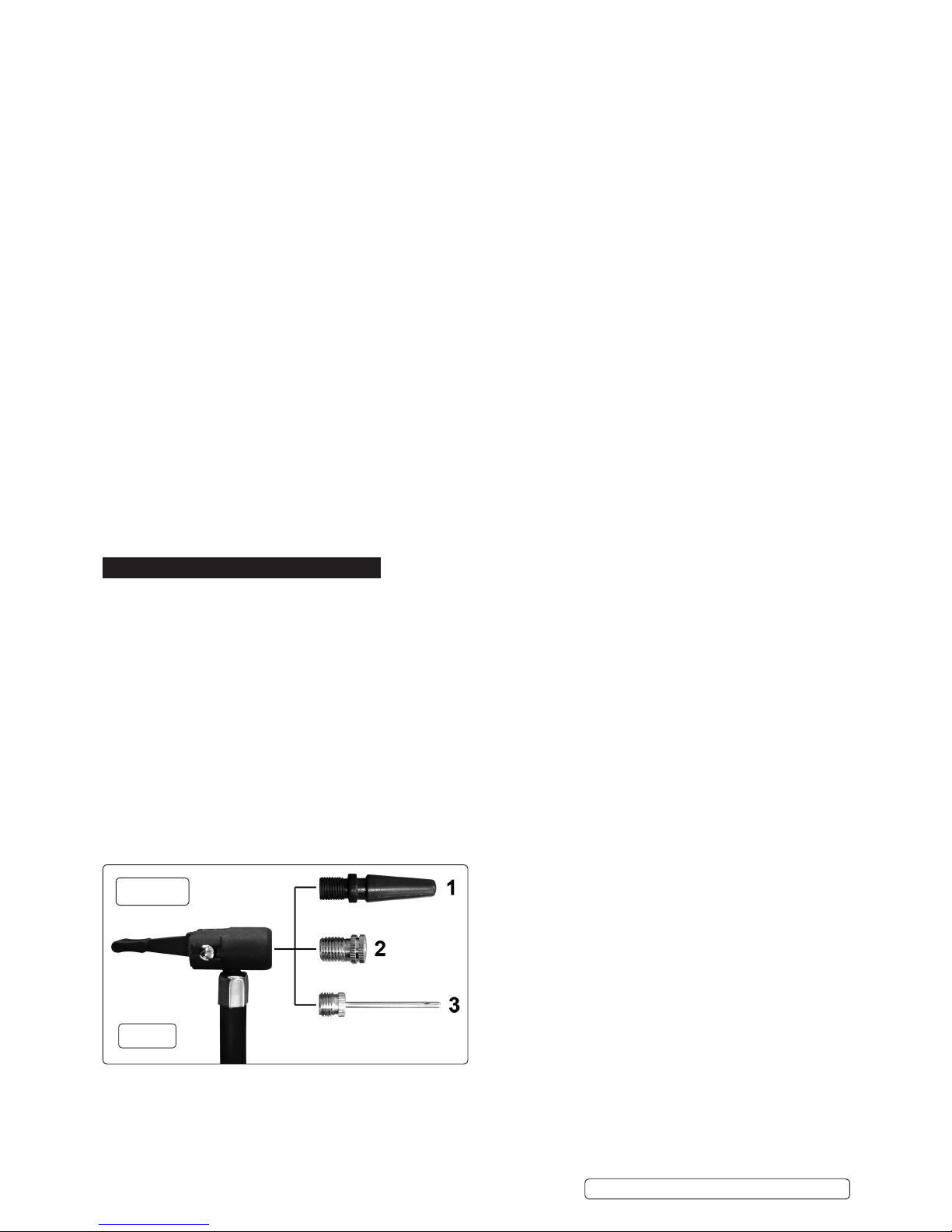
7.2.3. Identifythecorrectadaptorfortheproductandinsertitintotheinationconnectorasindicateding.9andpushthelocking
lever through 90º to lock it.
7.2.4. Insert the other end of the adaptor into the valve as far as possible.
7.2.5. Switchonthecompressorusingtheswitchontheunit(seeg.2-16)andmonitorthepressureontheairpressuregauge
(seeg.2-15).
7.2.6. When the desired pressure is reached, turn off the compressor, rotate the connector lever to the upright position and remove it
RS132
g.9
RS131.V3 RS132 | Issue 4(I) 21/05/15
Original Language Version
© Jack Sealey Limited

from the valve stem.
NOTE:Itisrecommendedtouseaseparateairgaugetodoublechecktheactualinationpressureachieved.
Replace any valve cover previously removed.
8. STORAGE
8.1. STORAGE
8.1.1. This unit may be stored in any position. Ensure that the clamps are securely attached to the clamping posts at the rear of the unit.
Store at room temperature. It is recommended to recharge the unit every three months when not in use and more frequently in
warmer or colder storage conditions to keep the battery in peak operating condition.
9. BATTERY REMOVAL/DISPOSAL
NOTE: The RoadStart battery is a sealed, lead-acid type. At the end of the RoadStart’s service life, by law, it must be removed
and recycled, or disposed of properly, according to national and/or local regulations.
9.1. REMOVAL
9.1.1. Place the RoadStart unit front side down.
9.1.2. Remove the 11 screws holding the casing together and lift off the back half of the unit.
9.1.3. Undo and remove the nuts, bolts and washers on each battery terminal. The connecting wires will now be loose.
9.1.4. Move the wires away from the two battery terminals, taking care to avoid accidental arcing of the terminals.
9.1.5. Lift the battery out of the front half of the casing.
9.2. DISPOSAL
9.2.1. Take the battery to a recycling centre that handles sealed, lead-acid batteries.
9.2.2. If there is no recycling centre in the area, contact the local environmental agency for disposal instructions.
10. TROUBLESHOOTING
QUESTION ANSWER
How many jump
starts can a fully
charged RoadStart
do before needing to
be recharged?
Between 1 and 20 depending upon
operating factors such as temperature,
general condition of the vehicle, engine type
and size.
Can the RoadStart
be recycled?
Yes, in accordance with national and local
authority regulations.
What is the ideal
in-use storage
temperature
of the RoadStart?
Room temperature. The RoadStart will also
operate at lower temperatures, its power
however will be lessened. Intense heat will
activate self-discharge.
I have a regular 10
amp battery charger,
can I use it to
recharge the
RoadStart?
No. Only the supplied charger can be used.
Is the RoadStart fool
proof?
No. All jump starting instructions must be
followed carefully.
Can I replace the
internal batteries?
Yes, but note that the batteries are not
covered by warranty as they are
consumable items
THE PROBLEM THE SOLUTION
Unit has been charged
for 36 hours but there
is no change in the
status of the LEDs
Check charger to see that it is charging.
Charger should be warm.
Check all wire connections
Charger works well but
still no change in LED
status.
Possible defective internal battery.
No LEDs come on, but
when the AC adaptor is
plugged into the unit
they do.
Roadstart unit battery defective which
could have been caused by intense use
without a cool-down period.
Roadstart unit is fully
charged but delivers no
power.
Check where the wires meets the jaw on
the unit clamps. Ensure they are well
crimped. Ensure that the safety switch is
in the ON position.
When connecting an
accessory via the dc
outlet there is no
power.
The accessory is drawing too much
current, resulting in the internal circuit
breaker operating. Allow to cool and
reset. Check accessory current draw.
RS131.V3 RS132 | Issue 4(I) 21/05/15
Original Language Version
© Jack Sealey Limited
NOTE: It is our policy to continually improve products and as such we reserve the right to alter data, specications and component parts without prior notice.
IMPORTANT: No liability is accepted for incorrect use of this product.
WARRANTY: Guarantee is 12 months from purchase date, proof of which will be required for any claim.
Sole UK Distributor, Sealey Group.
Kempson Way, Suffolk Business Park,
Bury St. Edmunds, Suffolk.
IP32 7AR
www.sealey.co.uk
sales@sealey.co.uk
01284 757500
01284 703534
Web
RS131.V3 RS132 | Issue 4(I) 21/05/15
Original Language Version
© Jack Sealey Limited
Environmental Protection
Recycle unwanted materials instead of disposing of them as waste. All tools, accessories and packaging should be
sorted, taken to a recycling centre and disposed of in a manner which is compatible with the environment.
When the product becomes completely unserviceable and requires disposal, and dispose of the product according to
local regulations.
WEEE Regulations
Dispose of this product at the end of its working life in compliance with the EU Directive on Waste Electrical and
Electronic Equipment (WEEE). When the product is no longer required, it must be disposed
of in an environmentally protective way. Contact your local solid waste authority for recycling information.
Battery Removal
Undo the eleven screws which hold the casing together and pull the casings apart. Disconnect the battery leads.
Under the Waste Batteries and Accumulators Regulations 2009, Jack Sealey Ltd are required to inform potential
purchasersofproductscontainingbatteries(asdenedwithintheseregulations),thattheyareregisteredwithValpak’s
registeredcompliancescheme.JackSealeyLtd’sBatteriesProducerRegistrationNumber(BPRN)isBPRN00705.
This manual suits for next models
1
Table of contents


