NovoPress HA1ES User manual
31070\B03eng
0496
OPERATING INSTRUCTIONS
FOR
HYDRAULIC DRIVE SYSTEMS
HA1ES / HA2

31070\B03eng
0496
Table of contents
Page
CE Conformity Declaration
Safety regulations
Technical data 1
Range of application 2
Construction 2
Connecting system tools 3
Three-phase safety pedal switch 4
Operation 5
Maintenance 6
Appendix: - Circuit diagram
- Hydraulics diagram

1
31070\B03eng
0496
Technical data
Electric motor:
Connection voltage: See identification plate
Power consumption: 800 W
Rotational speed: max. 10000 min-1
Mode of operation: S 3; 25 % 100 s
Protection class: 1
Mode of protection: IP - 44
Radio interference:As per VDE 0875
Power connection: Cable, 5 m long, with a three-phase safety
pedal switch and earthing contact-type plug
Hydraulics:
Hydraulic connection: Quick-action coupling plug with back-pressure valve
Operating pressure: 150 bars max.
Delivery capacity: at n = 1000 min-1:HA 1 = 0.45 l/min
HA 2 = 0,9 l/min
Dimensions: HA 1 ES: H = 470 mm; B = 250 mm; L = 280 mm
HA 2: H = 470 mm; B = 280 mm; L = 460 mm
Weight incl. oil: HA 1 ES: 18 kg
HA 2: 34 kg
Hydraulic oil: Oil filled in at works:
ISO VG 10 DIN 51519
(suitable for external temperatures from-5 to +35 °C)
Oil usable:
Oil in viscosity class:
ISO VG DIN 51519 from 10 to 46
(viscosity in CSt 7.4 - 30 at 50 °C)
Oil for temperatures < - 5 °C:
ISO VG 5 DIN 51519
2
31070\B03eng
0496
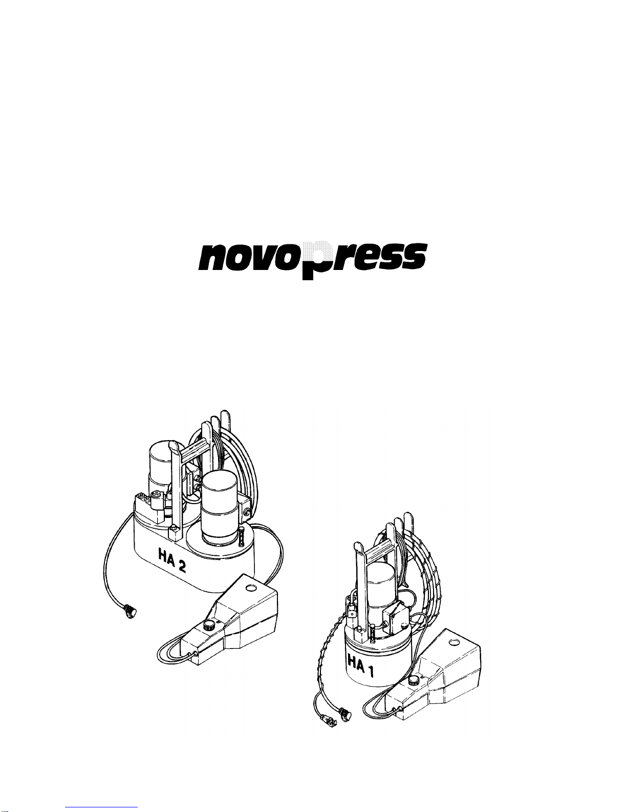
Hydraulic control units (basic equipment)
With respect to the hydraulic control units there are the following versions:
1. HA 1 ES Order No. 31070 Hydraulic control unit with 1 electric motor
2. HA 2 Order No. 31375 Hydraulic control unit with 2 electric motors
Range of application
NOVOPRESS hydraulic control units operate in the low-pressure range up to 150 bars, and they are
used as drive units for our hydraulic system tools.
Construction
The equipment meets the provisions of VDE 0740 for electric tools.
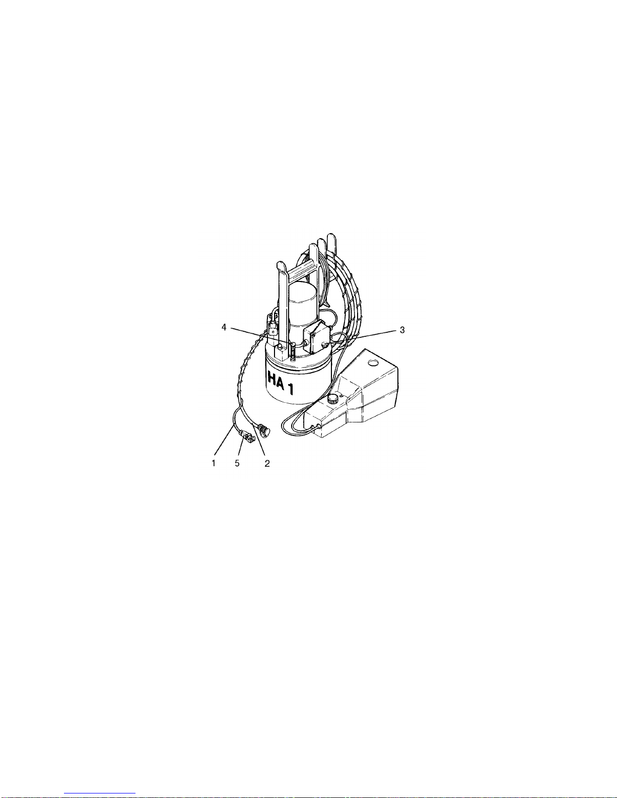
An oil-filling screw with breather valve (3) and an oil gauge (4) are mounted on the oil tank cover.
Oil gauge (4):
The gauge stick of the oil gauge must be between the two markings. If the gauge stick is at the
lowest marking, oil needs to be added.
Bleeding valve (3):
The air-relief valve closes if the tank is on the slant (no oil can emerge).
In the vertical position (operating position), a slight amount of oil vapour may be carried over with the
escaping air. The oil film which this causes on hydraulic equipment should be removed from time to
time.
Note:
The equipment must not be switched on while horizontal. There is a risk
that the pump will not draw in oil and is damaged as a result.
3
31070\B03eng
0496
Connecting system tools
The system tools are connected to the hydraulic control unit by means of the control line (1) and the
hydraulic hose (2), using the quick-action coupling.
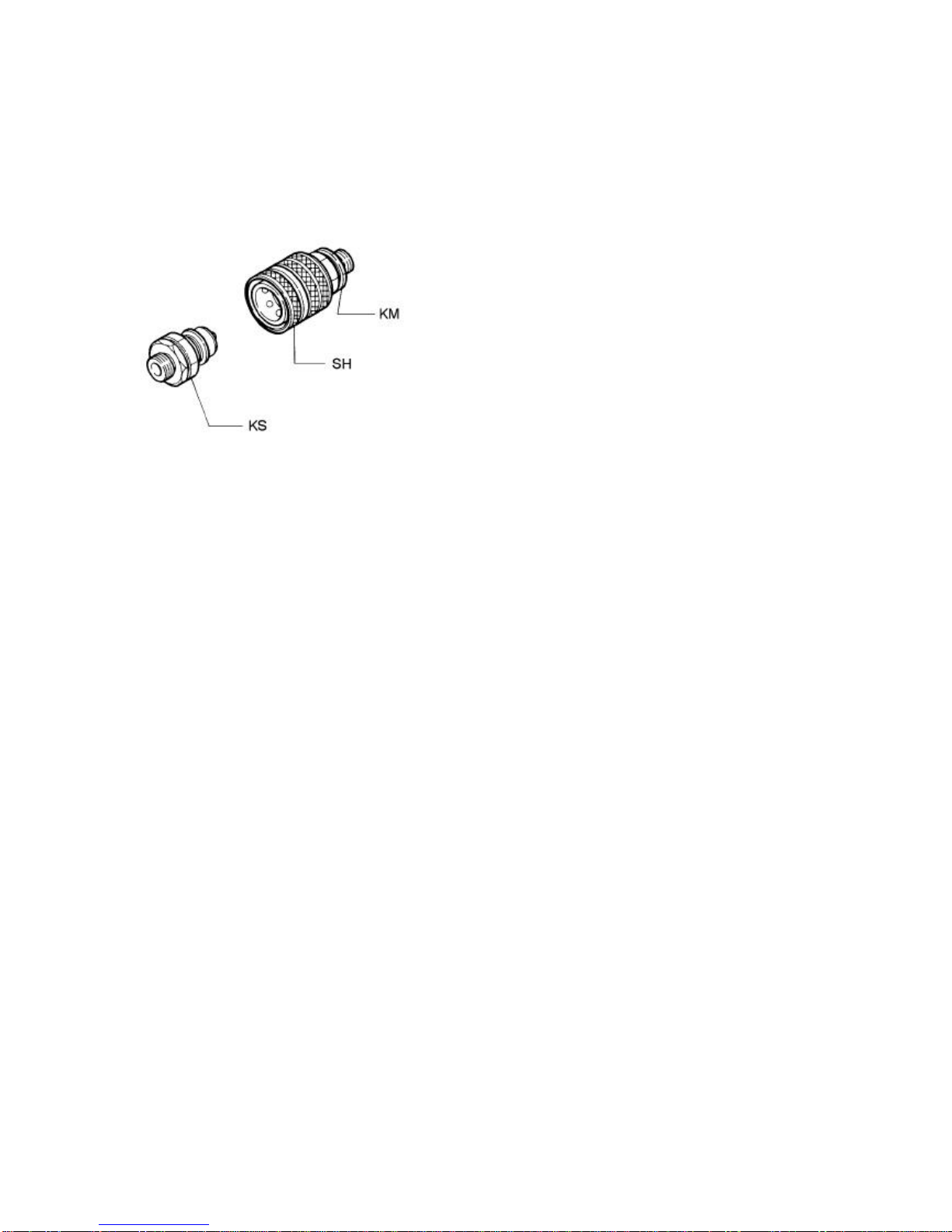
Connecting the hydraulic line
Quick-action coupling
Coupling-up
Hold the coupling socket (KM) up to the sliding
sleeve (SH), and slide it onto the coupling plug (KS).
Uncoupling
Hold the coupling socket (KM) at the sliding sleeve
(SH) and pull it of the coupling plug (KS).
Note:
- When changing the system tools, a small amount of oil will remain between the
back-pressure valves of the coupling.
- Handle the hydraulic hose with care. Bends at the connection points will lead to
premature breakdown. When coupling up, make sure that dirt does not penetrates the
coupling.
- Before coupling up another system tool, wipe out the coupling socket with a clean cloth -
that is free of fluff.
- The system tools should, as far as possible, remain coupled up at all times.
Connecting electrical leads
HA 1 ES
•Connect the control line (1) of the hydraulic control unit (HA 1 ES) to the system tool with the aid
of the plug connector (5).
HA 1 ES + HA 2
•Connect the mains cable to the power suply line.
Note:
Observe the mains voltage (see identification plate)!

4
31070\B03eng
0496
Three-phase safety pedal switch
1.
2.
3.
1. Pedal not actuated System tool "OFF"
2. Pedal actuated as far as detectable stop of pressure point System tool "ON"
3. Pedal actuated beyond pressure point "EMERGENCY OFF"
Pedal switch locked.
Note!
When EMERGENCY OFF is actuated:
-The hydraulic control unit is switched off and cannot be restarted by pressing the pedal again.
-To release the system, press the blue pushbutton (6).

5
31070\B03eng
0496
Operation
Note!
- The hydraulic unit can only be actuated with the manual button (located on the
system tool), or by the pedal switch.
The system tool which is connected will determine how the hydraulic device has
to be operated.
When the manual key is actuated, the EMERGENCY OFF function of the pedal
switch is active.
- The equipment must not be switched on while horizontal. There is a risk
that the pump will not draw in oil and is damagedas a result.
•Actuate the manual key or pedal switch, and hold it down.
Note!
When the manual or pedal switch is released, the piston of the system tool will return
immediately.
•The piston of the conected system tool will travel forwards.
The system tool is "working".
•Once the work process has been completed or the safety valve has responded, release the
manual key or the pedal switch immediately. Otherwise the oil will heat up unnecessarily.
Note!
- Care should be taken to ensure that the oil temperature does not exceed
70 °C during operation.
- Pressure can only be built up again once the key has been released and
actuated again.

6
31070\B03eng
0496
Maintenance
We recommend that our authorized NOVOPRESS specialist workshops be used for repair and
maintenance work.
Only have the equipment maintained by a specialist.
Caution! BEFORE ANY MAINTENANCE OR REPAIR WORK,
ALWAYS PULL OUT THE MAINS PLUG!
Check oil level
The gauge stick of the oil level indicator (4) must be between the two markings.
If it is at the lowest marking, oil must be added.
Top up the oil if necessary.
Oil change
First oil change: After about 1,000 starts, or after 3 months
Other oil changes: After every 15,000 starts, but at least once annually
Oil volume for: HA1 ES 3.5 litres
HA 2 6.5 litres
Hydraulic oil: See Technical Data
Oil filter: The oil filter is the suction strainer with a mesh width
of 0.06 mm.
•Unscrew the oil filling screw with the air-relief valve (3) on the oil tank cover.
•Draw off the old oil by means of suction.
•Fill with new oil.
Note!
The gauge stick of the oil level oil gauge (4) must be between the two markings.
Cleaning: Remove the oil film from the hydraulic unit every month.
Hydraulic hose: The hydraulic hose is to be checked for damage every month.
Replace hydraulic hose:
- If any cracks, crush points, or kinks are visible on the outer layer
- If blister formation is visible
- If pressurised fluid is escaping
- If the hose armature is damaged
- If any discolouration of the outer layer is visible,
e.g. due to the effect of solvents.
Hydraulic hoses must be replaced after 5 years, even if no
damage is visible.

7
31070\B03eng
0496
Visual and electrical inspection
Regularly: Check mains cable including plug and extension cord with plug connectors for
visible damage and have repaired, if necessary.
Every 6 months: Have an inspection complying with VBG 4 and DIN VDE 701, section 1 and
section 260, for electric devices of the protection class 1 carried out by a
qualified technician, an authorized workshop or Novopress Neuss.
Hydraulic drive unit H A 1 E S
Legend:
1 = Control line
2 = Hydraulic hose
3 = Air-relief valve
4 = Oil gauge
5 = Plug-in connector
6 = Pushbutton
7 = Pedal switch

Repairs / Service
Scharnhorststraße 1 PO Box 101163
D-41460 Neuss D-41411 Neuss
Telex 8 518 015
Tel. 02131 / 2880
Federal Republic of Germany Telefax 02131 / 28855
This manual suits for next models
1
Table of contents


