Sears, Roebuck and Co. 103.22160 Use and care manual

r
-_/
\
OPERATING INSTRUCTIONS
AND PARTS- LIST FOR
..
BENCH
8 INCH
SAW
rIi
I
Model Number 103.22160
The model number of your Bench Saw will be found on
a plate on the rear of the Base. Alwaysmention this
model number when communicating with us regarding
your Bench Saw or when ordering parts.
-=tnstf'uctions
rqr
OrderIng Parts
All parts listed herein must be ordered through a Sears
retail store or mail order house. Parts are shipped
prepaid. When ordering repair parts, always give the
followinginformation:
1. The Part Number.
2. The Part Name and Price.
3. The ModelNumber 103.22160.
This list is valuable. It will assure your being able to
obtain proper parts service. Wesuggest you keep it with
other valuable papers.
SEARS, ROEBUCK and CO.
LITHOGRAPHED IN U. S. A.
SOURCE FORM 37979
..

OPERATING
INSTRUCTIO~S
AND PARTS LIST FOR
8 INCH BENCH SAW
Model 103 22160
FIGURE 2
Insert with clips
Install in opening provided in table top. See Fig. 4.
INSTALLATION OF SAW:
There are four 5/16 diameter holes provided in
the base of the saw through which the tool should
be fastened securely with screws or bolts to a well
built work bench. A large hole in the bench below
the blade will allow sawdust to escape.
The Motor Mount Bracket should be installed as
shown in Fig. 2.
I. Set the saw at 0 inches elevation and 0 degrees
tilt. (See paragraph headed "Controls".)
FIGURE
-r
Careful planning, preCISIOn machining, and rigid Motor Mount
inspection have all contributed toward maintaining Install as shown in Fig. 2 and outlined under "Instal-
the high standard of quality found in this tool. We lation of Saw".
are confident that you will find it satisfactory in
every respect.
To increase the versatility of this saw beyond the
normal range of bench saw operations, various
attachments "are readily available.
To prevent damage in shipment some of the parts
were disassembled from the tool. These parts are
listed below. Be sure they are all accounted for be-
fore discarding any of the packing material.
I. Fence; item II I.
2. Miter gage assembly; item I23.
3. Motor alignment rod; item 17.
4. Motor mount complete; item 26.
5. Insert with clips; items 12, 13, 14 and 15.
6. Motor pulley; item 64.
7. V-belt; item 62.
ASSEMBLY:
Fence and Miter Gage
Install as shown in Fig. I.
Motor Alignment Rod
The 5/1 6 x 4 1/2 inch motor alignment rod, No. I7,
fits into the hole in the back of the splitter bracket.
Insert the rod as far as it will go into the bracket
and tighte:n the set screw.
2
r
•
2. Draw a line on the bench 5 inches from the
rear of the Saw base. (Measure at two points
12 inches apart to be sure that the line is par-
allel to the rear of base. )
3. Place the bracket, No. 22, on the bench as
follows; The end with the elongated hole 4 5/8
inches in from the left side of saw base and the
front edge on the line drawn previously.
Fasten it securely in this position.
4. Assemble motor rail, No. 2 I, and motor rail
guide and plate, No. 18, to the motor rail
bracket as shown. The grooved end of the
motor rail to be placed in end of bracket with
elongated hole.
5. Bolt your motor to the mount so that the motor
pulley will be in line with the saw pulley when
the motor alignment rod is through the slot in
the motor rail guide and plate.
Check before Operation
I
1. The motor alignment rod must project at
least 1/4 inch through the mount slot with the
blade retracted and tilted 45 degrees. This
setting should be checked often during opera-
tion. As the belt wears or stretches, loosen
the set screw and pull the alignment rod out
of the bracket the amount needed.
2. The motor mount must not strike the motor
mount bracket at either end of the motor rail
at 0 or 45 degrees tilt.
3. Be sure that the teeth of the blade point
toward the front of the saw and the top of
the blade turns toward the front.
MOTO,,:
For general home workshop use, a 1/2 horsepower
3450 RP.M. motor will provide adequate speed and
power. However, to enable you to take full advan-
tage of the rugged performance features and full
cutting efficiency of this saw, especially for heavy
duty work, a 3/4 horsepower 3450 RP.M. motor
should be used.
SPEED:
The motor pulley, No. 64, installed on a 3450 RP.M.
motor with a 1/2 inch diameter shaft will drive the
saw at the recommended speed-4500 RP.M.
BELT:
If your motor shaft is approximately 4 inches from
the bottom of the base of the motor, the V-belt, No.
62, should fit the installation previously described.
LUBRICATION:
The precision ball bearing assembly used on the saw
arbor has been packed with lubricant and sealed at
the factory. It should require no further attention for
the life of the bearing assembly.
To maintain the smooth, easy operation of the
controls, oil the following points occasionally;
1. The guide, No. 48, at the front cif the arbor
support.
2. The guide ways of the front and rear trun-
nions, Nos. 80 and 96.
3
3. The elevation screw, No. 76.
4. The motor rail, No. 21.
CONTROLS:
The Control Knob raises the saw from 0 to 2 1/2
inches above the table level when pushed in and
turned. It tilts the saw 0 to 45 degrees when pulled
out and turned.
The Angle of Tilt is shown by a pointer on the
scale just below the control knob.
The Depth of Cut Gauge and Pointer c~n be seen
through the curved slot to the left of the control
knob.
The Miter Protrador face is a guide surface for.
cross cutting or diagonal cutting to a definite angle.
The protractor may be used on either side of the
blade at any angle or depth of cut setting. The angle
is shown by the pointer on the calibrated scale on
the protractor head. The lock knob clamps the head
in the selected position.
CAUTION:
This saw has an extra long spindle for greater dado
capacity. If the blade is extended more than 2 3/8
inches according to the depth of cut gauge, the spindle
will strike the table insert when the saw blade is
tilted.
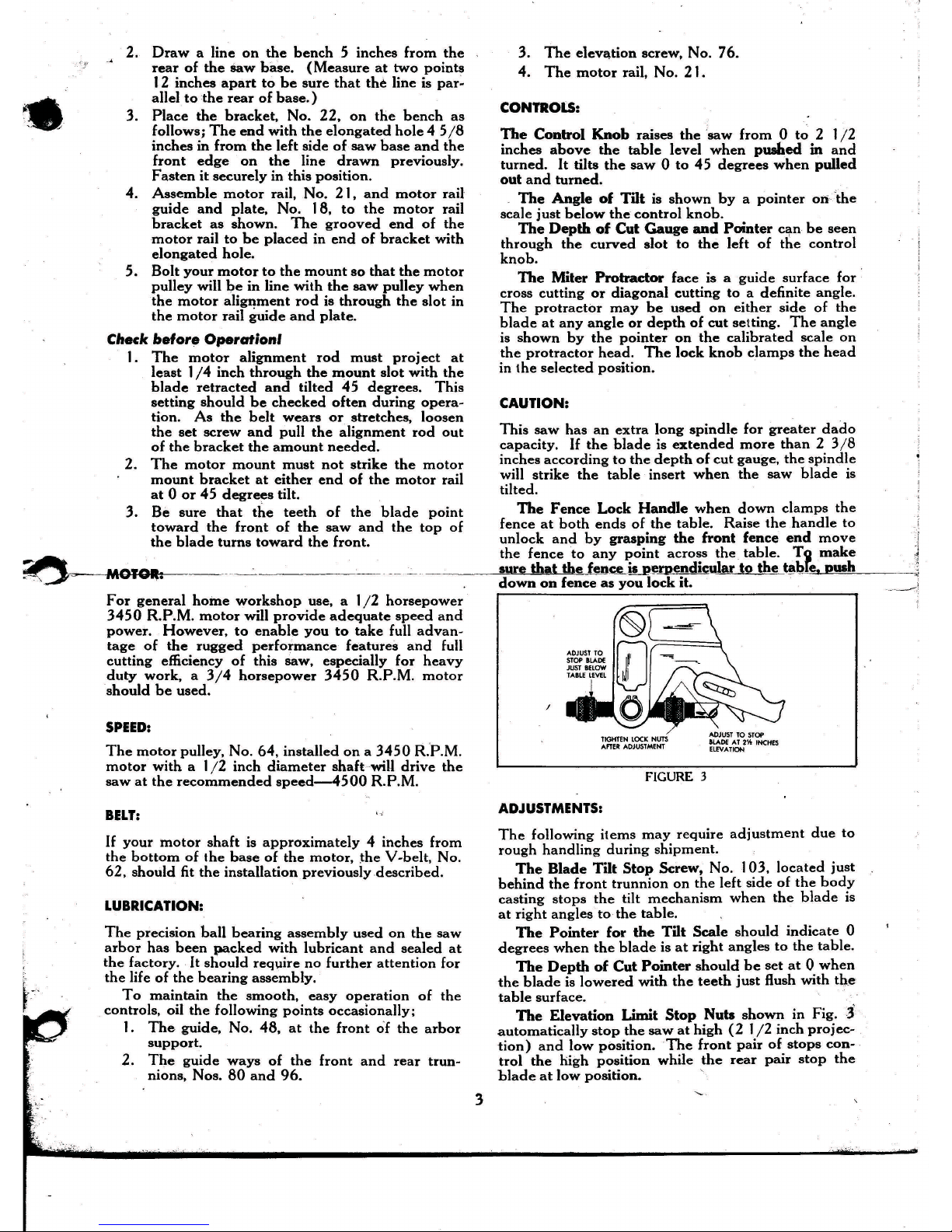
The Fence Lock Handle when down clamps the
fence at both ends of the table. Raise the handle to
unlock and by grasping the front fence end move
the fence to any point across the table. T~ make
sure that the fence~l rpendicular to the I lbfe, push
down on fence as you lock it.
/
TIGHTEN LOCK NUTS
AFTER ADJUSTMENT
FIGURE 3
ADJUSTMENTS:
The following items may require adjustment due to
rough handling during shipment.
The Blade Tilt Stop Screw, No. 103, located just
behind the front trunnion on the left side of the body
casting stops the tilt mechanism when the blade is
at right angles to the table.
The Pointer for the Tilt Scale should indicate 0
degrees when the blade is at right angles to the table.
The Depth of Cut Pointer should be set at 0 when
the blade is lowered with the teeth just flush with the
table surface.
The Elevation Limit Stop Nuts shown in Fig."
automatically stop the saw at high (2 1/2 inch projec-
tion) and low position. The front pair of stops con-
trol the high position while the rear pair stop the
blade at low position.

IAISE .LADE
,'AI
INC"S
DISTANCE'SHOULD
BE EOUAL.
TURN BLADE-
MEASURE FROM
SAME TOOTH AT
TABlE LEVEL
FENCEMUST LOCK
PARALLEL WITH
MITER SLOTS
FIGURE 4
The Blade Must Be Parallel with the Miter Slots
in the Table to Get a Straight Cut. (See Fig. 4).
Adjustment, if necessary, may be made as follows;
1. Raise the blade to 2 1/2 inches depth of cut
and set at right angle (0 degrees) to table.
2. Measure accurately from a raker tooth on the
blade to an edge of either miter slot, as ex-
plained and shown in Fig. 4.
3. Loosen the bolts, Nos. 79 and 97. holding each
trunnion, Nos. 80 and 96. to the lower table
surface. (4 bolts total.)
4. Shift the complete under-table mechanism until
the blade is parallel with the miter slot.
5. Re-tighten the four trunnion screws. front pair
first.
6. Check this adjustment as previously explained
fa
be
eel
lain it is correct-after re-assembly is
complete.
The Fence Must Lock Parallel with the Miter Slots.
Using one hand on the front end of the fence, slide
the fence to the edge of the miter slot. Push the lock
handle down slowly. If fence isn't parallel to miter
slot adjust as follows;
1. Loosen the two screws, NO.,1
OS;
,onthe under-
side of the front fence end. '
2. Release the fence lock handle.
3. Hold the fence flush to the edge of the miter
slot. Turn both screws up just snug. Then
tighten each one securely.
4. Check the adjustment by sliding the fence
away from the slot and returning several times
to see if it locks parallel each time.
The Fence Must Be Square with the Table Surface.
Adjust by loosening the screws, No. 10, holding the
fence slide bar to the table. Slide the bar up or down
at either end to square the face of the fence with the
table. Re-tighten the screws.
The Arbor Tilt Tension Spring, No. 100, provides
tension to keep the mechanism tilted at any angle,
thus eliminating the need for a manual control lock.
After
tlie,;tbol
is "broken in." you may find it neces-
sary to.lncr~~se this tension. Loosen the lock nut.
No. 90. and turn the bolt, No. 101, until enough ten-
sion has been applied. Re-tighten the lock nut.
Note: After a few hours of operation. tightep all
pulley set screws.
CARE OF THE BLADE:
Keep the blade teeth sharp and properly set.
To sharpen the blade;
1. Lower the blade until an oil stone laid on the
table will just touch the teeth. Rotate the
blade backward by hand until the ends of all
the small cutting teeth have been touched.
2. File the gullets (space between teeth) of all
teeth of the same shape to a uniform depth
and width. Maintain' the original shape,
bevels. and dimensions. Avoid sharp corners
or nicks in the gullets between the teeth.
3. The top one-quarter of each cutting tooth
should be set at an angle of approximately 10
degrees. The set should be uniform and should
alternate from left to right on successive teeth.
The large raker teeth require no set-they
should be kept approximately 1/64 inch
shorter than the cutting teeth.
4. File the bevel of each cuttingtooth-15 to 20
degree bevel on the inside front face of each
tooth. Maintain the original bevel angle and
be careful not to shorten the teeth.
Blade Wobble is often noticed at slow speeds
when starting or stopping the saw. If this does not
disappear at full speed, check the saw blade and
clamp washers for dirt or saw dust on the clamping
surfaces.
Gummy' residue can generally be removed with
kerosene. '
OPERATION:
- • <
The blade provided with this saw may be used for
Doth cross-cutling and ripping.
For proper chip clearance and best general results,
the blade should project through the work-piece ap-
proximately 1/4 inch.
Do not force material into the blade too fast. Use
a straight, direct, steady feed which does not over-
tax the cutting capacity of the blade.
To eliminate creep of your work when making a
miter cut, clamp the work piece to the.miter gage.
Support long work as it leaves the.re~of the table.
SAFETY:
While the bench saw is one of the most widely used
woodshop power tools, it is by nature of its general
design. one of the most dangerous in the hands of ,
inexperienced or careless operators. The bench saw -
is not, however. an unsafe tool when used with com-
mon sense and good judgment.
Use a push block rather than letting the hands get
closer than 3 inches to the blade on narrow cuts.
Never hold the hands over the blade when making
blind groove type cuts. Stand to one side when com-
pleting a cut. A loose piece caught J.)ythe blade can
fly back with surprising force.
Always stop the saw when removing waste stock
from near the blade, when making adjustments, or
when changing settings.
Donat wear dangling neck ties, loose baggy
sleeves, etc.• while operating power tools.

103
J-;-
102
126
122
9-
129
_128
127
26
MOTOR MOUNT
COMPlETE
17
16 /, 18
,/ ,/ j -
19
32_.~, ,.... _ /.--20
7
l ••
3130IJ/
29 28 27 ./
l
25
I
23
24
41
ITER GAGE ASSY.
M COMPLETE
123
5
55
FENCE ASSY.
COMPLETE
111
,
106
r
(
i
(,.
PARTS LIST
.20
.15
.20
.35
.\5
.10
.15
.15
. I 5
45
.10
1.50
5.30
.10
.10
1.60
.10
.10
.20
. I 5
.15
.10
.10
. I 5
.10
.15
.80
.10
.15
.15
1.60
.10
.10
• I 5
.20
.20
• I 5
.10
1.00
.10
.15
.10
1.25
.20
1.90
10.00
400
75
.10
.15
35
.20
.10
. 15
. I 5
1.00
.35
5.00
.\0
. I 5
2 50
3 25
.15
.75
Prepaid
Selling
Pric
Each
PART NAME
Motor pulley with set screw-2 % inch single
groove V-pulley % inch bore. Purchase from
your n ar st S ars r tail stor or mail ord r
house. Ask for Catalog No. 9-2802-% inch
bor .
Pivot b aring r taining scr w .
Pivot b aring r taining wash r .
Pivot b aring , .
Ball and pivot pin ..................•....
R taining ring .
Plain washer 4 I/64 J.D. x I
0.0 .
Spring wash r .
Fibr wash r .
Knurled stop nut ..............•.........
Saw l vation stud .
Hex nut %-20 .....•.....................
Saw elevation shaft ..............•.......
Arbor and bearing unit .
Set screw No. 10-24x',4 socket head cone pt.
Machine screw 5/16- I8 x
*
hex head with
xt rnal lock wash r .
R ar trunnion .
Set screw 5/1 6- I8x5 / I6 socket head cup pt .
Hex nut % .20 .......••..................
Splitter spacer .
Dish d fac splitt r wash r .
Splitt r clamp t nsion spring .
Cap screw %.20 x 2 hex head .
8 inch diameter combination blade. Purchase
from your n ar st S ars r tail stor or mail
order house. Ask for Catalog No. 9.4937-
'h inch bore ..•...................•....•
Hex nut %.20 jam nut : .
Saw clamp wash r .
Hex nut %.16 jam nut .
Spacer ..............•..................
Control gear .
Plain washer .
G ar cov r .
Machine screw % - 16 x I
*
hex head with ex.
ternal lock washer ......................•
Front Trunnion .
Machine screw 5/16. I8 x
*
hex head with
xt rnal lock wash r .
Fibre washer ........•...................
Flat washer ............•.....•...•.....•
Arbor tilt tension spring .
Arbor tilt tension bolt .•..................
T nsion plat spring .
Replace with Fillister head machine screw
%.20 x
* .
Fence slide .....................•.......•
Binding head screw No. 10-24 x
% .
Fence lock handle friction plate ....•.......
Machine screw % .20 x
*
flat head .
Fence lock handle ..•....•...............
Fence lock handle pivot pin .
Front fence end .
Fence assembly, complete ..•.............•
Fence body ..............•..............
F nc rod .
Hex nut %.16 .............•.............
F nc lock clamp pivot pin .
Fence lock clamp ..•.....................
Fence lock rod nut .
Plain washer % J.D. x 19/32
0.0 .
Rubber grommet .
F nc sho .
F nc nd r ar .
Fence lock rod .
Mit r gag ass mbly, compl t .
Machine screw No. 6.32 x 5/16 Fillister head
Mit r protractor point r .
Miter bar ..........•....................
Mit r protractor .
Plain washer 25/64 J.D. x
*
0.0 .
Lock knob .....•........................
37748
37752
37822
37648
37812
.X.379
37190
.X-380
37732
.X-542
37428
37641
37424
37006
37818
37643
X-413
37642
37425
37639
X-607
37825
37758
37426
37638
37109
X-554
37712
37110
37240
X-630
37411
65 37633
66 37823
67 37632
68 37622
69 18447
70 X-63 I
71 37744
72 38714
73 37649
74 37651
75 X-430
76 37652
77 38619
78 X.181
79 X-737
80 37417
81 X-I79
82 X.430
83 37646
84 18448
85 18449
86 .X.284
87 18992
Order
Illust. by
No. Part No.
64 18036-A
88 X-403
89 18444
90 X-413
91 37655
92 37429
93 X.630
94 37754
95 X.744
96 37422
97 X.737
98
99
100
101
f02
103
104
105
106
107
108
109
110
III
112
113
114
115
116
117
118
119
120
121
122
123
124
125
12 6 -'
127
128
129
.10
.10
.15
.15
.10
.10
.10
. I 5
.10
. I 5
.10
.10
.90
.10
.10
.10
1.20
.10
.15
.20
.10
.15
1.30
.10
.10
.80
.70
• I 5
.25
.10
3.25
.10
7.50
. I 5
.10;
.10
.60
.15
.10
.10
.60
1.60
14.00
.10
• I 5
X.179
Order
by
Part No.
Prepaid
Selling
Price
PART NAME Each
37009 Base ........•.....•.......•...•........ $ 11.00
X-1376 Speed nut No. 6.32 .15
37737 Front panel............................. 3.50
37763 Arbor tilt scale. ... . .. . .. . .. .. .. . . . . . . . . . .35
X.332 Machine screw No. 6.32 x % binding head. . .10
X.182 Set screw 5/16. I8x5 /16 socket head cone pt. .10
38120 Hand wheel with set screw,................ 2.25
X.1806 Sheet metal screw No. 7.16 x % .10
18635 Fence slide bar ..•....................... 1.20
.X-377 Binding head screw No. 10.24 x % .10
37211 Table ..•............ :.................. 26.00
X-375 Binding head screw No. 6.32 x
'AI ••••••.•••.
10
18993 Table insert clip . . . . .I5
37724 Table insert I. 10
X.245 I External tooth lock washer No.6. . . . . . . . . . . .I0
X.736 Machine screw ~.20x 1% hex head with
xt rnal lock wa'sh r .
37636 Motor alignment rod .....•.........•.....
37150 Motor rail guide and plate .
.X.605 Lock washer % inch ........•............
X.430 Hex nut %.20 ...........•...............
37654 Motor rail ... , ...•........•...•.........
37761 Motor rail brac;ket .•......•..............
3782 I Motor rail bushing ....•......•...•......•
37743 Motor rail bushing clip .
.X.20 1 Cap screw %.20 x
*
hex head .
37 I07 Motor mount. complete .
X.740 Machine screw %.20 x % hex head with ex.
ternal lock washer .
X- 100 Set screw % -20 x % slotted head cup pt .
374 18 Splitter bracket ...............•..........
X-622 Plain washer 17/32 J.D. x
%
0.0 .
37757 Tension washer ......•...................
37627 Spacer .
X. 741 Machine screw 5/16.18 x % hex washer head
with external lock washer .
.X-516 Machine screw No. 8.32 x % round head .
37722 Arbor tilt pointer ................•.......
37721 Depth of cut pointer .
.X.377 Binding head screw No. 10.24 x % .
X.734 Machine screw No. 10.24 x % round head
with external lock washer ...•.............
37751 Control shaft spacer plate .
37 I60 Shaft with gear .............••...........
37432 Frame ....•................ ,. ..•.........
X.f307 Steel ball 3/16 diameter .
373 10 Control shaft tension spring .
X.734 Machine screw No. 10.24 x % round head
• with xt rnal lock wash r .
111378.1121.,Tensionplate .
TenSion plate spring .
.X.20 1 Cap screw %-20 x
*
hex head .•..•.......
37423 Guide .
X-607 Plain washer %
1.0.
x 19/32
0,0 .
X.738 Machine screw % -20 x I round head with
~xternal
lock wash r ~ .
37320 Spindle support with bearing .
37634 Depth gage spacer .
37718 Depth of cut scale ..•....................
X-15H Eyelet
'AI
x % .
37 I30 Elevation indicator arm with scale .
37729 Spring washer .................•.........
X-628 Plain washer % J.D. x
%
0.0 .
X.732 Machine screw % .20 x 1% hex head with
int rnal lock wash r .
18035.B Tool pulley with set screw-2 inch single
groove V.pulley.
%
inch bore. Purchase
from your n ar st S ars
r tail
stor or
mail
order, house. Ask for Catalog No. 9-280 I-
%
inch bor .
Set screw 5/16.18 x 5/16 socket hd. cup pt ..
Allen wrench 5/32 ......•.................
V-belt 'h x 40 inches long. Purchase from ',_
your n ar st S ars r tail stor or mail ord r
house. Ask for Catalog No. 9.1640
j' :'
Set scr~ 5/16.18 x 5/16 socket hd. cup pt ' .. 10
X.179
.X-1400
X.1464
I
2
3
4
5
6
7
8
9
10
11
12
13
14
15
16
17
18
19
20
21
22
23
24
25
26
27
28
29
30
31
32
33
34
3'5
36
37
38
39
40
41
42
43
44
45
46
47
48
49
50
51
52
53
54
55
56
57
58
59
60
61
62
63
Illust.
No.
'Parts marked in this manner may be purchased locally.
This sh t is int nd d for. instruction and r pair parts only and is not a packing slip. Th parts shown and list d may includ acc ssori s not
necessarily part of this tool. All parts ',r. ' shipped prepaid. All prices are subject to change without notice .
.
~
6
b C
I
3 1,500-4.52
1
I
t
Table of contents
Other Sears, Roebuck and Co. Saw manuals


Popular Saw manuals by other brands


Carter Products
Carter Products DELTA Series manual

Scheppach
Scheppach HM90SL Translation of original instruction manual

GRABBER
GRABBER GR871 instruction manual

Hitachi
Hitachi C 12YB Handling instructions

Axminster
Axminster Hobby MS210S instructions

Clarke
Clarke CTS800C Operation & maintenance instructions