Sears, Roebuck and Co. 103.23420 User manual

OPERATING INSTRUCTIONS
AND PARTS LIST FOR
BENCH SAW
7-INCH
Model Number 1 3.2342
This is the model number of your Bench Saw. It will be found on a
plate on the right side of the base. Always mention this model
number when communicating with us regarding your Bench Saw
or when ordering parts.
How to Order Parts
All parts must be ordered through a Sear's retail or mail order store.
Parts are shipped prepaid. When ordering repair parks, always
give the following information:"
1. The Part Number.
2. The Part Name
3.The Model Number 1 3.2342 which will be found
on a plate on the right side of the base.
This list is valuable. It will assure your being able to obtain proper
parts service. We suggest you keep it with other valuable papers.
SEARS, ROEBUCK and CO.
Source Form 33919

OPERATING INSTRUCTIONS AND PARTS LIST FOR
CRAFTSMAN BENCH SAW
Model 1 3.2342
ASSEMBLING
This bench saw was completely inspected and tested at the factory. To prevent
damage during shipment, the fence assembly, the guard and splitter
assembly and the miter gage assembly were packed separately in an
enclosed carton.
Before reassembling, check the alignment of the saw blade with one of the
miter slots in the table. If the distance from the front and rear blade edge to
the miter slot is not equal, loosen the two hex head cap screws which hold the
table tilt protractor (Figure 2) to the table and shift the table until the blade.
and miter slot are parallel.
Install the guard and splitter by inserting the splitter pin (Figure 1) into the
hole in the rear of the table support No. 3318 . With a straight edge, align the
splitter and saw blade before tightening the set screw X1 2. After loosening
the rip fence clamp knob and rip fence lock knob (Figure 2) slide the fence
into position so that it grips the protruding lip of the rear fence guide bar No.
18624 and slides over the front fence guide bar No. 33716 as illustrated. Place
the miter gage on the table so that the bar rests in the miter slot as shown in
Figure 3.
LUBRICATION
Before operating this saw, remove the two oil plugs over the spindle bearings
(Figure 2) and fill the reservoirs with a good grade machine oil of S.A.E.
viscosity No. 2 . Use an oil can with a small spout, or a pressure can so that air
in the reservoirs may be more easily displaced. Replace the plugs after oiling.
The reservoirs extend completely around the bearing, and should be kept full
of oil.
The bronze bearings used in this saw are designed to absorb, filter, and meter
oil to the spindle. The bearings contain invisible pores which become
saturated with oil. When the bearings and spindle become warm during
operation, the oil flows through the bearings to the revolving spindle.
Caution: Do not drill holes through the bearings to feed oil to the spindle.
Oil should be applied occasionally to the other moving and sliding parts of the
bench saw to maintain smooth operation.
FIGURE I-ASSEMBLY
2

CONTROLS
The table crank (Figure 2) when turned will raise or lower the table in
relation to the saw blade, thus regulating the depth of cut as indicated
on the depth of cut scale.
The table clamp screw locks the table in position, and therefore
should be loose during adjustment of table height. The table lock
handle, with its hexagon recess is designed for use as a wrench on the
table lock nut No. 33422 to clamp the table in position at any angle
from ' to 45' as shown on the table tilt protractor. The handle may be
slid off the nut toward the saw and will hang in a neutral position when
not in use.
NOTE: The table must be raised at least 1/4 inch from the lowest setting
before tilting.
The rip fence clamp knob will clamp the fence to the front fence bar
and will square the fence with the table if tightened while the lock
knob is loose. The lock knob when tightened will lock the far end of
the fence in place.
The face of the miter gage may be set at any desired angle from 3 ' to
9 ' in either direction by loosening the miter protractor lock knob and
turning the protractor to the desired angle as shown on the calibrated
scale.
ADJUSTMENTS
If a square cut is not produced with a setting of the table tilt protractor, lower
the table to the full depth of cut position and check the squareness of the blade
and table with a square. Adjustment may be made with the table leveling
screw shown in Figure 3. Following this adjustment, the table protractor
pointer should be reset at the mark. This may be accomplished by backing
out the pointer screw X512 until the pointer can be turned to the desired
position. Care should be exercised so that the pointer does not move when the
screw is tightened. Raise the table 1/4 inch and tilt it 45' as indicated on the
table tilt protractor. Adjust the 45'
stop screw shown in Figure 3 so that the table is supported when tilted 45'. The
jam nut on the stop screw must be retightened after adjustment.
The miter gage may be checked with an accurate try-square and the pointer
reset at 9 ' if adjustment is necessary after setting the protractor square with
the bar No. 3324 .
FIGURE 2-CONTROLS
The rip fence must be parallel with the saw blade to produce straight cuts and
avoid binding. After the alignment of the miter slots and saw blade have been
checked, as previously described, slide the edge of the fence
to the edge of the miter slot and tighten the clamp knob and lock knob in
order mentioned. If the fence is not parallel with the miter slot, loosen the lock
knob and the two screws shown on either side of the clamp knob in Figure 3.
With the lock knob and the two screws loose, the fence may be pivoted until it
is parallel with the miter slot. Tighten the lock knob. After the fence is set as
described above, tighten the two screws securely to maintain the adjustment
just completed.
3
FIGURE 3-ADJUSTMENTS
3

SPEED
This bench saw will give best results when operated at approximately 45
R.P.M. Satis. factory operating speed and power can be obtained with a 1/2
horsepower 345 R.P.M. motor equipped with a 2-1/2 inch diameter pulley, or
a 1/2 horsepower 175 R.P.M. motor equipped with a 5 inch pulley. If the saw
is to be used for light work only, a 1/3 horsepower motor with the above
speed and pulley combinations will provide sufficient power. Direction of
rotation must be clockwise when viewed from pulley side of saw.
This saw is designed to be driven either from below or from the rear. If the
motor is installed behind the saw, clearance must be provided for the drive
belt when the table is in the lowest position. The motor pulleys mentioned
above are available from Sears Retail or Mail Order Stores. For the 5 inch
pulley ask for catalog number 9-28 5, for the 2-1/2 inch pulley ask for number
9-28 2. Be sure to specify the shaft diameter of your motor.
Under normal circumstances any slight wobble apparent when the blade is
rotated slowly will disappear at operating speed. If, however, the blade does
not run true at operating speed, clean the contact surfaces of the saw clamp
washers and the blade, and reinstall the saw clamp washers with the recessed
side against the blades.
To insure accuracy during cross cutting operations the angle between the
miter protractor face and the blade should be checked frequently with a
square.
Caution: Always stop the blade before making a check of this type.
The rip fence should be used when making a series of ripping cuts. To move
the fence, loosen both the lock knob and the clamp knob. Slide the fence to
the point at which the distance from the fence edge to the blade equals the
desired width of cut. Tighten the clamp knob and lock knob in the order
mentioned. A trial cut should be made to check a setting of this type. When
ripping narrow strips, always use a pusher of scrap wood to prevent injury
when finishing a cut.
When possible, the table should be adjusted so that the blade projects
through the work piece 1/4 to 1/2 inch to allow dust and chips to be cleared
from the blade.
For continuous ripping operations, a rip saw blade will give best results,
likewise, a cross cut blade will give beat results if continuous cross cutting
operations are planned.
Where maximum accuracy is desired, as with interior trim work, a hollow
ground combination saw blade should be used, since it is much better suited
for precision work than the flat combination blade.
This saw may be used for disc sanding by removing the table insert No. 19971
and replacing the blade with a 1/2 inch bore sanding disc. The table may be
tilted to sand angle cuts. To change the abrasive, soak the disc in hot water
and peel off the paper. Dry the disc thoroughly before cementing the new
abrasive.
The guard should be in position over the blade at all time during sawing
operations.
Due to the variety of installations possible, a guard cannot be supplied for the
V-Belt. However, it is recommended that suitable protection be provided by
the operator.
During continuous operation, the operator may experience a slight electrical
shock upon touching the bench saw. This is a discharge of accumulated static
electricity generated by the friction of the moving parts, such as the belt and
the pulley. This may be eliminated by attaching a ground wire from the bench
saw to a water or heating pipe.
CARE OF THE SAW BLADE;
When the blade requires sharpening, before filing the teeth, first make sure
that they are all of the proper length. Raise the table until an oil stone will rest
flat on the top of the table just above the saw. Lower the table until the teeth
just touch the stone. With the belt removed, rotate the blade slowly backward
until the ends of all the small teeth have been touched. Stone the small teeth
just enough so they will all be the same length.
File the gullets of all teeth of the same shape to a uniform depth and width.
Maintain the original shape and dimension when filing the teeth. Be careful not
to cut a nick or sharp corner in the bottom of the gullet, which might cause the
blade to crack.
Use either a setting stake or a hand set to provide uniform set for the small
scoring teeth. Set only the top 1/4 of each scoring tooth. The large raker teeth
of combination saw blades require no set. After setting the scoring teeth,
check to see that all teeth are in alignment at each side. If some teeth are set
too much, they may be corrected by filing. If the set is too light, use the saw
set to correct the condition.
After setting, file the bevel of the scoring teeth h. The bevel must alternate
from one side to the other on successive teeth. Maintain the original bevel
angle, and be careful not to shorten the teeth. Make sure that all scoring teeth
are of the same length. File the face as well as the back of the scoring teeth.
The large raker teeth should be filed straight across with no bevel. These
raker teeth should be about 1/64 inch shorter than the small scoring teeth,
PARTS LIST
4
Part
No.
Prepaid
Selling
Price
Each
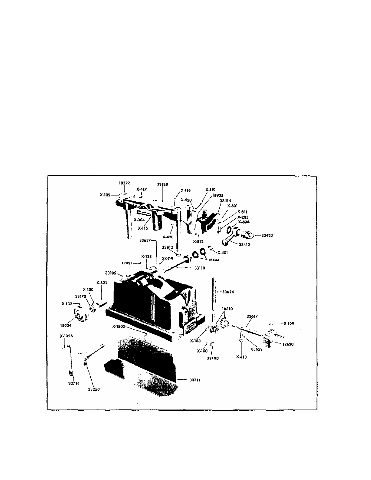
BASE AND RELATED PARTS
38 34 Pulley and Set Screws Single Groove--2 in. V-Pulley
1/2, in. Bore. Purchase from Div. 9 in Sears Retail
Stpre
18444 Saw Clamp Washer. $ .2
18522 Table Pivot Pin. .2
18626 Handwheel, 1.15
1881 Bevel Gear and Set Screw. .4
1893, Oil Hole Plug , .15
16935 Table Tilt Protractor Pointer .15
331 5 Base Ass'y, includes 2-X822 Bearings.
2-38931 Oil Plugs., 33714 Depth of Cut Scale
14.5
3311 Spindle 1.25
3317 Spindle Collar Set Screw. .3
3318 Table Support 5.
3319 Cella, & Set Screw .25
3325 Table Elevation Lack .45
33412 Table Tilt Lack Handle .5
Part
No.
Prepaid
Selling
Price
Each
33414 Table Tilt Protractor .75
33419 Depth of Cut Pointer .15
33422 Table Tilt Lock Nut .35
33617 Table Crank Shaft .5
33622 Retaining Screw .15
33624 Lift Screw .45
33627 Depth of Cut Pointer Rod. .15
33711 Base Partition .95
33714 Depth of Cut Scale .15
33812 Snap Pin .15
X-822 Spindle Bearing .25
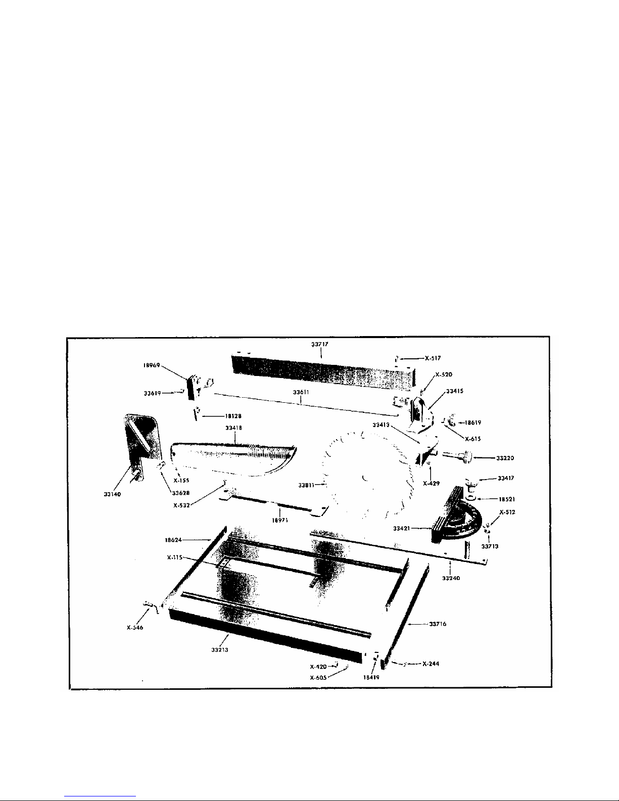
TABLE AND RELATED PARTS
18128 Fence Clamp .15
18419 Fence Guide Spacer .15
18521 Lock Knob Washer .15
This sheet is intended for instruction and repair parts only and is not a packing slip. The parts shown and listed may, include accesssories not necessarily part of this tool.
All prices are subject to change without notice. All parts we shipped prepaid
FIGURE 5--BASE AND RELATED PARTS
5
Part No.
Part Name
Prepaid
Selling
Price Each
18619 Fence Clamp Knob .25
18624 Fence Guide Bar-Rear .4
18969 Fence End-Rear .5
18971 Table Insert .6
331 1 Rip Fence Assembly Complete 4.5
331 2 Miter Protractor Ass'y Complete 1.75
3314 Splitter .5
33213 Table 11.75
3322 Fence Clamp Knob 5
3324 Miter Protractor Bar .5
33413 Fence Equalizer .85
33415 Fence End-Front .65
33417 Lock Knob .35
33418 Saw Guard 1.95
33421 Miter Protractor .95
33611 Fence Lock Rod .4
33619 Fence Rod Nipple. .2
33628 Saw Guard Pivot Pin .15
33733 Miter Protractor Pointer .15
33716 Fence Guide Bar--Front .75
33717 Fence 1.5
33611 Flat Ground Combination Saw.- 7 in. Dia, 1/2 in Bore
Purchase from Div. 9 in Sears Retail Store
THE FOLLOWING PARTS ARE STANDARD AND
MAY BE PURCHASED LOCALLY.
Part No.
Part Name
Prepaid
Selling
Price Each
X-1 1 Set Screw -., 1/4-2 x 1/4 Slotted Head Cup Point .1
X-1 2 Set Screw 1/4--2 x 1/2 Square Head Cup Point .1
X 1 8 Set Screw 5/16-24 x 3/8 Slotted Head Cup Point .1
X-1 9 Set Screw No. 1 -24 x 1/4 Slotted Head Cup Point .1
X-11 Set Screw 1 1/4-2 x 3/4 Square Head Cup Point .1
X-135 Set Screw No. 1 -24 x 3/8 Slotted Head Cup Point .1
X-136 Set Screw 1/4-2 x 1 Square Head Cup Paint .1
X 128 Set Screw No. 6-32 x 1/4 Slotted Head Cup Point .1
X 132 Set Screw 5, 16-18 x ¼ Slotted Head Cup Point .1
X-155 Set Screw No. 1 -24 x 3/8 Slotted Head Cone Point .1
X 2 5 Fillister Head Cap Screw 5/16-18 x 3/4 .1
X-244 Fillister Head Cap Screw 1/4-2 x 1 .15
X-3 4 Square Head Machine Bolt 3/8-16 x 2. .1
X-4 1 Hex Nut 1/2-2 .1
X-413 Hex Nut 3/8-16 .1
X-417 Hex. Nut 5/16-18 .1
X-42 Hex. Nut 1/4-2 .1
X-429 Hex Nut No. 1 -32 .1
X 512 Round Head Mach. Screw No. 8-32 x 1/8 .1
X 517 Round Head Mach. Screw 1/4 -2 x 5/8 .1
X 52 Flat Head Mach. Screw No. 1 -32 x 1 .1
X-532 Fillister Head Mach Screw No. 1 -24 x 7/16 .15
X-546 Fillister Head Mach. Screw 1/4-2 x 3/4 .15
X WI Plain Washer 5/16 Std. .1
X-6 5 Lock Washer ¼ Std. .1
X-6 6 Plain Washer 3/8 Std .1
X-611 Lock Washer 5/16 Std. .1
X-615 Plain Washer 1/4 Std. .1
X-1326 Drive Screw No. 4 x 3/16 .1
X-18 3 Sheet Metal Screw No. 12 x 5/8 Binding Hd. .1
FIGURE 5--TABLE AND RELATED PARTS
6
Table of contents
Other Sears, Roebuck and Co. Saw manuals


