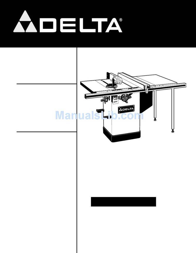
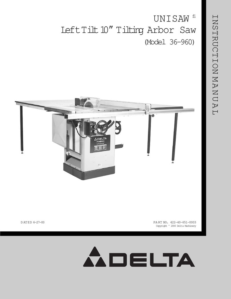
Delta 36-475 User manual

INSTRUCTION MANUAL
REVISED 6-14-99 PA RT NO. 422-19-651-0042
'Delta International Machinery Corp. 1999
Platinum Edition
10"Contractor s Saw
with 30" Unifencefi
(Model 36-475)

2
TABLE OF CONTENTS
SAFETY RULES....................................................................................................................................................................................3
ADDITIONAL SAFETY RULES FOR CIRCULAR SAW S.....................................................................................................................4
UNPACKING AND CLEANING..............................................................................................................................................................5
ASSEMBLY INSTRUCTIONS
Assembling Saw Stand...............................................................................................................................................................7
Assembling Saw To Stand .........................................................................................................................................................8
Assembling Blade Tilting Handwheel .......................................................................................................................................8
Motor ............................................................................................................................................................................................9
Assembling Motor To Motor Mounting Plate............................................................................................................................9
Assembling Motor And Motor Mounting Plate To Saw ...........................................................................................................9
Assembling Motor Pulley,Belt And Pulley Guard, And Drive Belt ......................................................................................10
Connecting Motor Cord To Switch Assembly ........................................................................................................................11
Assembling Blade Guard And Splitter Assembly..................................................................................................................12
Assembling Extension W ing....................................................................................................................................................15
Assembling Switch To Extension W ing ..................................................................................................................................15
Assembling Table Mounting Brackets To Saw Table ............................................................................................................16
Assembling Table Legs And Front Table Support .................................................................................................................17
Assembling Unifence Table To Saw ........................................................................................................................................19
Assembling Unifence Guide Rail.............................................................................................................................................20
Assembling Cursor To Unifence Body ...................................................................................................................................21
Assembling Unifence Body To Guide Rail .............................................................................................................................22
Assembling Fence To Unifence Body.....................................................................................................................................23
CONNECTING SAW TO POWERSOURCE
Power Connections...................................................................................................................................................................23
Extension Cords........................................................................................................................................................................24
Grounding Instructions ............................................................................................................................................................24
120 Volt, Single Phase Operation ............................................................................................................................................24
240 Volt, Single Phase Operation ............................................................................................................................................25
FASTENING STAND TO SUPPORTING SURFACE...........................................................................................................................25
OPERATING CONTROLSAND ADJUSTMENTS
Starting And Stopping S a w ......................................................................................................................................................25
Locking Switch in The OFF Position ...................................................................................................................................25
Overload Protection..................................................................................................................................................................26
Raising And Lowering The Blade............................................................................................................................................26
Tilting The Blade .......................................................................................................................................................................26
Adjusting 90 Degree And 45 Degree Positive Stops .............................................................................................................26
Backlash Adjustments For Blade Raising And Blade Tilting Mechanisms ........................................................................27
Miter Gage Operation And Adjustment...................................................................................................................................27
Adjusting Table Insert...............................................................................................................................................................28
Changing The Saw Blade .........................................................................................................................................................28
Storing The Miter Gage, Rip Fence, And Arbor Wrenches ...................................................................................................29
Dust Chute .................................................................................................................................................................................29
Fence Operation........................................................................................................................................................................29
Adjusting Fence Parallel To Miter Gage Slots .......................................................................................................................30
Adjusting Fence 90 Degrees To Table ....................................................................................................................................31
Adjusting Clamping Action Of Fence Locking Handle .........................................................................................................31
Repositioning Motor For Storage ............................................................................................................................................31
OPERATIONS
Cross-Cutting ............................................................................................................................................................................32
Using The Fence As A Cut-Off Gage.......................................................................................................................................33
Ripping With The Unifence ......................................................................................................................................................33
Ripping On Left Side Of Saw Blade ........................................................................................................................................34
Using Accessory Moulding Cutterhead ..................................................................................................................................35
Using Accessory Dado Head ...................................................................................................................................................36
Using Auxiliary Wood Facing On The Rip Fence ..................................................................................................................37
Constructing A Push Stick .......................................................................................................................................................38
PARTS, SERVICE OR W ARRANTYASSISTANCE............................................................................................................................39
WARRANTY.........................................................................................................................................................................................40

3
SAFETY RULES
W oodworking can be dangerous if safe and proper operating procedures are not followed. As with all machinery, there are certain
hazards involved with the operation of the product. Using the machine with respect and caution will considerably lessen the possi-
bility of personal injury. However, if normal safety precautions are overlooked or ignored, personal injury to the operator may result.
Safety equipment such as guards, push sticks, hold-downs, featherboards, goggles, dust masks and hearing protection can reduce
your potential for injury.But even the best guard won t make up for poor judgment, carelessness or inattention. Always use common
sense and exercise caution in the workshop. If a procedure feels dangerous, don t try it. Figure out an alternative procedure that feels
safer. REMEMBER: Your personal safety is your responsibility.
This machine was designed for certain applications only. Delta Machinery strongly recommends that this machine not be modified
and/or used for any application other than that for which it was designed. If you have any questions relative to a particular applica -
tion, DO N O T use the machine until you have first contacted Delta to determine if it can or should be performed on the product.
DELTA INTERNATIONAL MACHINERY CORP.
MANAGEROFTECHNICAL SERVICES
246 ALPHADRIVE
PITTSBURGH, PENNSYLVANIA 15238
(IN CANADA: 644 IMPERIAL ROAD, GUELPH, ONTARIO N1H 6M7)
W ARNING: FAILURE TO FOLLOWTHESE RULES
M AY RESULT IN SERIOUS PERSONALINJURY
1. FORYOUROWNSAFETY, READ INSTRUCTION
MANUALBEFORE OPERATING THE TO O L. Learn the
tool s application and limit ations as well as the specific
hazards peculiar to it.
2. KEEPGUARDSINPLACE and in working order.
3. ALWAYSWEAREYEPROTECTION.
4. REMOVEADJUSTING KEYSANDWRENCHES. Form
habit of checking to see that keys and adjusting wrenches are
removed from tool before turning it on.
5. KEEP WORKAREACLEAN. Cluttered areas and
benches invite accidents.
6. DON TUSEINDANGEROUSENVIRONMENT. Don t
use power tools in damp or wet locations, or expose them
to rain. Keep work area well-lighted.
7. KEEPCHILDREN AND VISITO R S A W AY . All children
and visitors should be kept a safe distance from work area.
8. MAKEWORKSHOPCHILDPROOF with p adlocks,
master switches, or by removing starter keys.
9. DON T FORCE TOOL. It will do the job better and be
safer at the rate for which it was designed.
10. USE RIGHT TOOL.Dontforce tool or att achment to do
a job for which it was not designed.
11. WEARPROPERAPPAREL.Noloose clothing, gloves,
neckties, rings, bracelets, or other jewelry to get caught in
moving parts. Nonslip footwear is recommended. Wear
protective hair covering to contain long hair.
12. ALW AYS USE SAFETY GLASSES.W ear safety glasses.
Everyday eyeglasses only have impact resist ant lenses;
they are not safety glasses. Also use face or dust mask if
cutting operation is dusty.
13. SECUREWORK. Use clamps or a vise to hold work
when practical. It s safer than using your hand and frees
both hands to operate tool.
14. DON TOVERREACH.Keep proper footing and balance
at all times.
15. MAINTAIN TOOLSINTOPCONDITION. Keep tools
sharp and clean for best and safest performance. Follow
instructions for lubricating and changing accessories.
16. DISCONNECT TOOLS before servicing and when
changing accessories such as blades, bits, cutters, etc.
17. USERECOMMENDEDACCESSORIES. The use of
accessories and attachments not recommended by Delt a
may cause hazards or risk of injury to persons.
18. REDUCE THE RISK O F UNINTENTIONAL START-
IN G . Make sure switch is in OFF position before plugging
in power cord.
19. NEVER STAND O NTOOL. Serious injury could occur
if the tool is tipped or if the cutting tool is accident ally
contacted.
20. CHECKDAMAGEDPARTS. Before further use of the
tool, a guard or other part that is damaged should be care-
fully checked to ensure that it will operate properly and
perform it s intended function check for alignment of moving
parts, binding of moving parts, breakage of parts, mounting,
and any other conditions that may affect its operation. A
guard or other part that is damaged should be properly
repaired or replaced.
21. DIRECTION OF FEED.Feed work into a blade or cutter
against the direction of rot ation of the blade or cutter only.
22.
NEVERLEAVE TOOLRUNNING UNATTENDED. TURN
POWEROFF
. Don t leave tool until it comes to a complete
stop.
23. DRUGS, ALCOHOL, MEDICATION. Do not operate
tool while under the influence of drugs, alcohol or any
medication.
24. MAKESURETOOLIS DISCONNECTED FROM POWER
SUPPLY
while motor is being mounted, connected or re-
connected.
25. W ARNING: The dust generated by certain woods and
wood products can be injurious to your health. Always oper-
ate machinery in well ventilated areas and provide for proper
dust removal. Use wood dust collection systems whenever
possible.
4
ADDITIONAL SAFETY RULES FOR
CIRCULAR SAW S
1. A LW A Y S use blade guard and splitter with anti-
kickback for every operation for which it can be used,
including thru-sawing operations. Thru-sawing operations
are those when the blade cuts completely through the
workpiece as in ripping or cross-cutting.
2. A LW A Y S hold the work firmly against the miter gage
or fence.
3. A LW A Y S use a push stick for ripping narrow stock.
Refer to ripping applications in instruction manual where
the push stick is covered in detail. See push stick p attern
included in this instruction manual.
4. NEVER perform any operation free-hand which
means using your hands to support or guide the work-
piece. Always use either the fence or miter gage to posi-
tion and guide the work.
5. NEVER stand or have any part of your body in line
with the p ath of the saw blade. KEEP your hands out of
the line of the saw blade.
6. NEVER reach behind or over the cutting tool with
either hand for any reason.
7. MOVE the rip fence out of the way when cross-
cutting.
8. NEVER use the fence as a cut-off gage when cross-
cutting.
9. DIRECTION O F FEED. Feed work into a blade or
cutter against the direction or rot ation of the blade or
cutter only.
10. WHENcutting moulding, NEVER run the stock be-
tween the fence and the moulding cutterhead.
11. NEVERattempt to free a st alled saw blade without
first turning the saw O F F . T urn of f switch immediately to
prevent motor damage.
12. T H E U S E ofattachments and accessories not
recommended by Delta may result in risk of injuries.
13. PROVIDE adequate support to the rear and sides of
the saw table for wide or long workpieces.
14. AV O ID kickbacks (work thrown back toward you) by:
A. Keeping blade sharp.
B. Keeping rip fence parallel to the saw blade.
C. Keeping splitter and anti-kickback fingers and
guard in place and operating.
D. Not releasing the work before it is pushed all the
way past the saw blade.
E. Not ripping work that is twisted or warped or does
not have a straight edge to guide along the fence.
15. AVOID awkward operations and hand positions where
a sudden slip could cause your hand to move into the
cutting tool.
16. NEVERuse solvents to clean plastic p arts. Solvent s
could possibly dissolve or otherwise damage the material.
Only a soft, damp cloth should be used to clean plastic
parts.
17. PERMANENTLY mount the saw to a supporting sur-
face before performing any cutting operations.
18. NEVER cut metals or material which may make
hazardous dust.
19. A LW A Y S. use in a well-ventilated area. Remove saw-
dust frequently. Clean out sawdust from the interior of the
saw to prevent a potential fire hazard.
20. D O N O T expose your saw to rain or use in a damp
location.
21. ADDITIONAL INFORMATION regarding the safe
and proper operation of this product is available from the
National Safety Council, 1121 Spring Lake Drive, It asca,
IL 60143-3201, in the Accident Prevention Manual for
Industrial Operations and also in the Safety Data Sheets
provided by the NSC. Please also refer to the American
National Standards Institute ANSI 01.1 Safety Require-
ments for Woodworking Machinery and the U.S. Depart-
ment of Labor OSHA 1910.213 Regulations.
22. SAVE THESE INSTRUCTIONS. Refer to them fre-
quently and use them to instruct others.

5
UNPACKING AND CLEANING
Carefully unpack the t able saw and all loose items from the shipping containers. Remove the protective coating from
the machined surfaces of the saw.This coating may be removed with a soft cloth moistened with kerosene (do not
use acetone, gasoline or lacquer thinner for this purpose). Fig. 2, illustrates the components ofthetable saw. Fig.3,
illustrates the components of the saw stand. Fig. 4, illustrates the components of the Unifence fi
1. Contractor s Saw
2. Blade Tilting Handwheel
3. Handwheel Lock Knob
4. Blade Guard and Splitter Assembly
5. Table Insert
6. Miter Gage
7. Miter Gage Handle
8. Miter Gage Handle Cap
9. S plitter Mounting Bracket
10. 1/4-20 x 3/4† Hex Head Screws (2)
11. 1/4† Flat Washers (2)
12. 5/16-18 x 5/8† Carriage Head Screw
13. 5/16† Flat Washer
14. 5/16-18 Hex Nut
15. Arbor Wrenches (2)
16. Cast Iron Extension Table
17. 7/16-20 x 1-3/4† Hex Head Screws
for assembling extension table (3)
18. Flat Washers for assembling
extension wing (3)
19. 1/4-20 x 3/4† Flat head Screw
20. Flat Washer
21. Hex Nut
Fig. 2
1
6
2
3
5
7
8
9
11
10
14
13
12
15 18
17
16 21 20
19
4

6
1. Combination Dust Chute/
Support Panel
2. Motor Pulley
3. Motor
4. Pulley Guard
5. Drive Belt
6. S pring
7. Pins (2) for Mounting Motor
8. Motor Mounting Plate
9. Lockwashers (4)
10. Flat Washers (4)
11. 5/16-18 x 3/4† Carriage
Head Screws (4)
12. Hex Nuts (4)
13. 5/16 † Hex Nuts (8)
14. 5/16 † Lockwashers (8)
15. 5/16† Flat Washers
16. 5/16-18 x 5/8† Hex Head
Screws (8)
17. Rubber Feet (4)
18. #10-32 x 12 Screws (8)
19. #10 Keps Nuts (8)
20. #10-1/2†Sheet Metal
Screws (3)
21. Grommet
22. Front Leg Panel
23. Rear Leg Panel
1. Unifence Body
2. Fence
3. Shelf Support Bracket
4. Front Table Support
5. Table Board
6. Table Legs (2)
7. Front Guide Rail
8. Leg Adapter (2)
9. Flat Washers (2)
10. Leveling Screws (2)
11. Z-Brackets (2)
12. 7/16-20 x 3/4† Hex Head
Screws, Lockwashers,
and Flat Washers (3 ea.)
13. U-Bolts (2)
14. Angle Brackets (3)
15. 1/4-20 x 3/4† Carriage Head
Screws, Flat Washers, and
1/4-20 Hex Nuts (3 ea.)
16. Flat Washers and 1/4-20
Hex Nuts for U-Bolt s (4 ea.)
17. #8 x 13/16† Hex Washer
Head Screws (14)
18. Threaded Studs for
Guide Rail (2)
19. 3/8† x 24 Hex Nuts (2)
20. Guide Rail End Caps (2)
Fig. 3
Fig. 4
21
22
20
18
19 17
16
15 14
12
10
13
11
9
7
8
6
5
4
3
2
1
23
6
7
10
9
8
12
15
14
13
16
17
18
19
20
1
2
3
45
11

7
ASSEMBLY INSTRUCTIONS
Fig. 5
Fig. 6
Fig. 7
ASSEMBLING SAW STAND
1. Assemble the dust chute and support panel (A)
Fig. 5, to the inside of the front st and panel (B) with three
#10 x 1/2† sheet metal screws (C), four #10-32 x 1/2 †
screws (D), and four hex nuts (E). Fig. 6, illustrates the
dust chute and support panel (A) assembled to the front
ofst and (B). NOTE: The front st and panel will have the
saw identity labels facing you. Do not completely tighten
the st and hardware at this time. Also, make certain the
dust chute/support panel (A) Fig. 6, is located under the
lipoffrontstand panel (B).
2. Assemble the other end of dust chute and support
panel (A) Fig. 7, to rear st and panel (F) as shown with
four #10-32 x 1/2† screws and hex nuts, three of which
are shown at (D). NOTE: Do not completely tighten stand
hardware at this time.
B
C
E
D
A
A
B
A
D
D
F

8
Fig. 9
Fig. 10
Fig. 11
ASSEMBLING
SAW TO STAND
1. Fig. 8, illustrates the st and (B) completely assem-
bled.
2. Assemble rubber foot (A) Fig. 8, onto the end of
each stand leg (B). Insert grommet (C) into hole (D) in
stand leg.
3. Carefully place saw (E) Fig. 9, onto saw stand (B).
Align eight holes in the top of st and (B) with mounting
holes in the bottom of saw (E) and fasten with eight screws,
flat washers, lockwashers, and hex nuts (F) Fig. 8.
4. Fig. 9, illustrates the saw (E) assembled to the saw
stand (B). Carefully push down on the top of the saw until
the st and legs are positioned firmly on the floor surface
and securely tighten all saw and stand mounting hard-
ware. Notice that panel (G) is not only a support for a
stand, but also serves as a dust chute.
ASSEMBLING BLADE
TILTING HANDWHEEL
1. Assemble blade tilting handwheel (A) Fig. 10, to
shaft (B). Make certain slot (C) in handwheel is engaged
with roll pin (D) on the shaf t.
2. Thread locking lever (E) Fig. 11, onto shaf t.
3. Fig. 11, illustrates the blade tilting handwheel (A) and
locking lever (E) assembled to the saw.
E
B
G
DB
AC
A
E
Fig. 8
D
B
C
A
E
FF

9
MOTOR
The motor shipped with your saw is a 1-1/2 H.P., Ball Bearing, Capacitor Start/Capacitor Run, 115/230
V olt motor.
This motor has been specially selected to best supply power to your machine and the relative safety of
the machine is enhanced by its use. We, therefore, strongly suggest that only this motor be used, as
the use of other motors may be detrimental to the performance and safety of the saw.
Fig. 12
Fig. 15Fig. 14
ASSEMBLING MOTO R TO
MOTO R MOUNTING PLATE
W ARNING: WHENASSEMBLING THE MOTO R TO THE
MOTO R MOUNTINGPLATE, MAKE CERTAINTHESAW
IS DISCONNECTED FROMTHEPOWERSOURCE.
1. Assemble the motor (A) to the motor mounting plate
(B) as shown in Fig. 12, using four carriage bolts,flat
washers, star washers, and hex nuts (C).
NOTE: Do not completely tighten the hex nuts at this
time.
ASSEMBLING MOTO R
AND MOTO R MOUNTING
PLATE TO SAW
W ARNING: WHENASSEMBLING THE MOTO R AND
MOTO R MOUNTINGPLATE TO THESAW , MAKE CER-
TAIN THE S AW IS DISCONNECTED FROMTHEPOWER
SOURCE.
1. Insert two pins (X) Fig. 13, into holes (D) in each side
of bracket (B). Assemble spring (Y) onto ends of pins (B)
as shown.
2. Position motor and motor mounting plate (A) Fig. 13,
below bracket (B) to allow bracket arm to slide through
large opening in motor mounting plate (A).
3. Depress plungers (X) Fig. 14, on both sides of brack-
et (B) and rot ate motor mounting plate (A) until plungers
(X) are engaged in holes (D) Fig. 13, of motor mounting
plate (A).
A
C
B
B
D
A
C
B
CA
Fig. 13
4. Fig. 15, illustrates the motor and motor mounting
plate assembled to the rear of the saw.
XYX

10
Fig. 16
Fig. 17
Fig. 18
Fig. 19
ASSEMBLING MOTO R
PULLEY, BELT AND
PULLEY GUARD, AND
DRIVE BELT
W ARNING: WHEN ASSEMBLING MOTO R PULLEY,
BELT A N D PULLEY GUARD, A N D DRIVE BELT, MAKE
CERTAIN THE MOTO R IS DISCONNECTED FROM
THEPOWERSOURCE.
1. Remove the motor shaft key that is t aped to the
motor.
2. Insert the key (A) Fig. 16, in the keyway on the motor
shaft.Assemble the motor pulley (B) on the motor shaft
as shown, with the hub of the pulley facing out. Tighten
set screw (C) against key (A) in motor shaft.
3. Remove wing nut and external tooth lockwasher (D)
Fig. 17, and outer cover (E) from belt and pulley guard (G).
4. Slide the belt and pulley guard bracket (G) Fig. 18,
between the motor plate (M) and motor mounting plate
(L), as shown.
5. Position belt and pulley guard bracket (G) Fig. 19, so
the motor pulley (B) is centered and through the hole in
the belt and pulley guard bracket, as shown. Tighten the
four hex nuts that fasten the motor to the motor mounting
plate.
6. Using a straight edge, align the motor pulley with the
arbor pulley. If necessary, adjust the motor pulley (B)
Fig. 19, in or out on the motor shaft.
B
A
C
GD
E
M
L
G
G
B

11
Fig. 20
Fig. 21
Fig. 22
Fig. 23
7.Lift the motor and assemble the drive belt (H) Fig. 20,
to the arbor pulley and motor pulley (B). The weight of
the motor will provide the correct belt tension.
8. W ARNING: IMMEDIATELY AFTER ASSEMBLING
T H E B E LT, RAISE T H E S AW BLADETO ITS MAXIMUM
HEIGHT AND TILT THE S AW BLADETO 45 DEGREES.
CHECKTO SEEIF THE MOTO R END BELL (J) FIG. 21,
ISBELOWTHETOPOFTHETABLE SURFACE(K). IF
THE MOTO R END BELL (J)IS ABOVETHETOPOF
THETABLESURFACE, THE M O TOR MUST BE MOVED
TO THE LEFT UNTIL Y O U AR E CERTAIN THE END
BELL (J)OFTHEMOTORISBELOWTHETOPOF
THETABLESURFACE. THEN RE-ALIGN THE M O TO R
PULLEY TO THE ARBORPULLEY.
9. Assemble the outer cover (E) Fig. 22, of the belt and
pulley guard assembly, which was removed in STEP 3,
and fasten with external tooth lockwasher and wing nut
(D). IMPORTANT:Make certain the outer cover does not
interfere with the drive belt and the motor pulley.
CONNECTING MOTO R CORD
TO SWITCH ASSEMBLY
W ARNING: BEFORE CONNECTING MOTO R CORDTO
THE SWITCH ASSEMBLY, MAKE CERTAIN THESAW
IS DISCONNECTED FROMTHEPOWERSOURCE.
1. Insert the pronged motor plug (A) Fig. 23, into the
female receptacle (B) of switch-to-motor cord (C).
H
B
K
J
D
E
C
B
A

12
Fig. 24
Fig. 25
Fig. 26
Fig. 27
2. Fig. 24, illustrates the motor cord connected to the
switch assembly.
ASSEMBLING
BLADEGUARD AND
SPLITTER ASSEMBLY
W ARNING: MA KE CERTAIN THE SAW IS DISCON-
NECTEDFROMTHEPOWERSOURCE.
1. Fasten the rear splitter mounting bracket (A) Fig. 25,
to the rear trunnion using the two 3/4 † hex head screws
(B) and flat washers. Do not completely tighten the two
screws (B) at this time.
2. W ith wrenches supplied, remove the saw blade from
the saw. Refer to section CHANGING THE SAW BLADE
on page 28, of this manual. Raise saw arbor to its high -
est position.
3. Remove screw and large washer (C) Fig. 26, from
the inside splitter mounting bracket.
4. Using a straight edge, check to see if the top and
bottom of the inside splitter bracket (D) Fig. 27, is aligned
with the inner arbor flange (E), as shown.
BA
C
D
E

13
Fig. 28
Fig. 29
Fig. 30
Fig. 31
5. If an alignment is necessary, loosen the two screws
(F) Fig. 28, align bracket (D) with the arbor flange (E) and
tighten screws (F).
6. Loosely assemble large washer and screw (C) Fig. 28,
to the inside splitter bracket. This screw and washer was
removed in STEP 3.
7. Assemble the blade guard and splitter assembly (G)
Fig. 29, between the large washer (C) and the splitter
bracket and tighten screw (H) with wrench supplied.
8. Fasten the rear of the blade guard and splitter bracket
assembly (G) Fig. 30, to the rear splitter mounting
bracket using 5/8† carriage bolt (J) , flat washer, and hex
nut. IMPORTANT:The splitter (G) Fig. 30, has a notch
(L) cut in the top edge as shown. This feature will enable
the blade guard to stay in the raised position to make
blade changing a little easier. Simply raise the front of
blade guard (M) Fig. 31, until the rear edge of the blade
guard slip s into notch (L) of splitter (G); the blade guard
willst ay in this position.
C
D
F
G
H
C
GL
J
G
L
M
E

14
Fig. 32
Fig. 33
Fig. 34
Fig. 35
9. W ith the blade guard (L) Fig. 32, in the raised posi-
tion, assemble the saw blade (K) on the saw arbor with
two arbor wrenches supplied.
10. Using a straight edge, check to see if the saw blade
is aligned with the rear of the splitter (G), as shown in
Figs. 33 and 34. If alignment is necessary, loosen the
screws (A) Fig. 34, align splitter (G) with the saw blade,
and tighten two screws (A).
11. Lower saw blade and installt able insert (P) Fig. 35,
in the saw t able as shown. IMPORTANT:When installing
the table insert, always make certain to hold on to the
blade guard (L). The insert will automatically release the
holding action on the splitter and lower the blade guard
when it is inst alled in the t able opening.
L
K
G
G
A
L
P

15
Fig. 37
Fig. 38
Fig. 39
ASSEMBLING
EXTENSION WING
1. Assemble extension wing (A) Fig. 36, to the saw
table using three 7/16-20 x 1-1/4 † screws (B) and lock-
washers (C) as shown in Fig. 37.
ASSEMBLING SWITCH
TO EXTENSION WING
1. Assemble switch (A) Fig. 38, behind the lip of exten-
sion wing (B) with 1/4-20 x 3/4† flat head screw (C), flat
washer, and locknut.
2. Fig. 39, illustrates the switch assembled to the exten -
sion wing.
2. W ith a straight edge (D) Fig. 36, make certain the
extension wing (A) is level with the saw table before
tightening three screws (B) Fig. 37.
Fig. 36
C
B
A
D
B
B
A
C
B

16
Fig. 40
Fig. 41
Fig. 42
Fig. 44Fig. 43
ASSEMBLING TABLE
MOUNTINGBRACKETS
TO SAW TABLE
1. Assemble Z-brackets (A) Fig. 40, to the three t apped
holes at the inside edge on the right side of saw table (B),
using three 7/16-20 x 3/4† hex head screws (C) with flat
washers and lockwashers.
2. Using a square (D) Fig. 41, make certain the
Z-brackets (A) are perpendicular to the saw table as
shown. Also,lift upward on Z-brackets (A) while tighten -
ing screws (C) to eliminate any play.
3. Fig. 42, illustrates the Z-bracket s assembled to the
saw blade.
4. Assemble angle bracket (E) Fig. 43, onto Z-bracket
(A) using 1/4-20 x 3/4 † carriage bolt (F) with flat washer
and hex nut. IMPORTANT:The longer leg of angle
bracket (E) must be secured to Z-bracket (A). Assemble
the remaining two angle brackets to the edge of the t able
in the same manner.
5. Using a square (G) Fig. 44, set the angle brackets so
they are approximately 3/4†from the top of the saw t able.
Final adjustments to angle brackets will be made later.
B
C
A
D
A
A
F
AE
FE
E
G

17
ASSEMBLING TABLELEGSAND FRONT TABLE SUPPORT
Fig.45
Fig. 46
Fig. 47
1. The table board supplied will require thirteen 1/8 †
diameter x 3/8† deep holes to be drilled in the bottom of
thetable board at the locations illustrated in Fig. 45.
2. Assemble table leg (A) Fig. 46, to table board (B) using
four #8 x 7/8 † long wood screws (C) as shown. Assemble
remaining table leg to the t able in the same manner.
CAUTION: D O NOT OVER-TIGHTEN LEG MOUNTING
SCREWS.Over-tightening screws in particle board may
cause them to strip.
3. Fasten front t able support (D) Fig. 47, to the bottom
oftable using two 7/8† long wood screws (E) as shown.
CAUTION: D O NOT OVER-TIGHTEN SCREWS(E).
Over-tightening screws in particle board may cause them
to strip. Do not completely tighten the two screws (E) at
this time, as adjustment is necessary.
A
B
C
E
E
D

18
4. Insert foot adapter (T) Fig. 48, into the bottom of each leg (A). Assemble the 3/8† jam nut (V)
Fig. 48, approximately 3/4 of the way onto leveling screw (W) and place a flat washer (X) on the level -
ing screw.Thread the leveling screw (W) Fig. 48, into foot adapter. Fig. 49, illustrates the foot leveling
assembly on the table leg. Assemble the remaining foot assembly to the other table leg in the same
manner.NOTE: Height adjustments can be made later.
Fig. 50
5. Assemble shelf support bracket (M) Fig. 50, to the
table legs (A) using two U-clamps (N), flat washers, and
hex nuts (P). NOTE: Height adjustments to the bracket
can be made later.
Fig. 49
Fig. 48
NM
P
N

19
Fig. 51
Fig. 52
Fig. 53
Fig. 55Fig. 54
BA
B
ASSEMBLING UNIFENCE
TABLE TO SAW
1. Position t able board (A) Fig. 51, onto angle brackets
(B).
2. While holding table board firmly against the saw
table, fasten t able to three angle brackets (B) Fig. 52,
using three #8 x 7/8† long wood screws (C). CAUTION:
DO NOT OVER-TIGHTEN TABLEMOUNTING SCREWS.
Over-tightening screws in particle board may cause them
tostrip.
3. Using a straight edge (D) Fig. 53, make certain the
surface of the Unifence table (A) is level with the saw
table (F) by adjusting the height of the two leveling
screws (E) Fig. 54, at the base of the table legs and
adjusting the height of angle brackets (B) Fig. 55. Once
the Unifence table is level with the saw t able, tighten
three hex nuts (G) Fig. 55, and position hex nuts (H)
Fig. 54, against the bottom of the table legs to hold the
leveling screws in position.
C
A
C
FA
D
G
G
H
H
E
B
B
B
B

20
Fig. 56
Fig. 57
Fig. 58
Fig. 59
D
D
C
B
A
E
ASSEMBLING
UNIFENCE GUIDE RAIL
1. Locate the cardboard template (A) Fig. 56, from the
packing material of the Unifence.
2. Place two 3/8†-24 hex nuts, one of which is shown at
(B) Fig. 56, in position on the two t abs of the template (A).
3. Insert template (A) Fig. 56, into the channel at the
end of guide rail (C) as shown, until the hex nuts (B) line
up with two holes (D) in guide rail.
5. Assemble the guide rail to the saw table by inserting
two studs (E) Fig. 58, into the two matching holes (F) in
the front of the saw t able. Fasten guide rail (C) Fig. 58, to
the saw table with two flat washers and hex nuts (G).
6. Adjust the guide rail (C) Fig. 59, parallel with the saw
table surface by placing a square (H) on the saw table at
both the lef t and right front ends of the t able, with the rule
of the square against the flat surface on top of the guide
rail. The guide rail (C) Fig. 59, can be adjusted up or
down slightly at either end. After you are cert ain the
guide rail is p arallel with the t able surface, firmly tighten
the two hex nuts that fasten the guide rail to the t able.
4. Locate two double-threaded studs (E) Figs. 56 and
57, and thread the short finer threads as shown, into the
hex nuts (B) Fig. 56, located on the template (A) inside
the channel of the guide rail. Remove the cardboard
template from the inside of the guide rail. E
E
E
G
G
E
G
GE
E
F
F
H
C
C
Table of contents
Other Delta Saw manuals

Delta
Delta 36-714B User manual

Delta
Delta 36-412 User manual

Delta
Delta 422-32-655-0004 User manual

Delta
Delta ShopMaster S26-263L User manual

Delta
Delta 36-255 User manual

Delta
Delta 16 SM600 User manual

Delta
Delta 36-312 User manual

Delta
Delta 28-255 User manual

Delta
Delta 40-570 User manual

Delta
Delta 36-5000 User manual

Delta
Delta 20-330 User manual

Delta
Delta 36-441B User manual

Delta
Delta 20-140 User manual

Delta
Delta 36-5052 T2 User manual

Delta
Delta 36-040 User manual

Delta
Delta Sidekick 36-210 User manual

Delta
Delta T2-30 User manual

Delta
Delta ShopMaster 638518-00 User manual

Delta
Delta 36-648 User manual

Delta
Delta Unifence 36-905 User manual