manuals.online logo
Brands
  1. Home
  2. •
  3. Brands
  4. •
  5. Sears
  6. •
  7. Measuring Instrument
  8. •
  9. Sears 161.2124 User manual

Sears 161.2124 User manual

Sears
owners mqnuol
introduclion
PLUG IN THE TEST TEADS BEFORE
The plug ond socket ore polorized to insure
correct ottochment.The rccket hos o groove on
eoch lop edge ond the plug hos o mofing ridge
on the inside of the top corners.
This instrument iq supplied with removeoble plug-
in test leqds for eose in storoge ond replocement.
Before using this instrument, insert the coble os-
sembly plug into ihe socket on the front of the
teste r .
USING THE TESTER
UP
t
t-t
ENO VIEW
OF PLUG
I MPOR,TANI
The informotion in this monuol will serve os o generol guide for
engine tune-up.
CONSULT THE OWNERS MANUAL OF THE VEHICLE BEING
TESTED FOR SPECtFtC TUNE-UP INFORMATION, ENGINE
IDLE SPEED, DWELL ANGLE, ETC.
RU LES FOR SAFE OPERATION
l. Set the porking broke ond ploce ihe geor
shift lever in Neutrol or Pork position.
2. Work on the vehicle in o well ventiloted
oreo to ovoid donger of corbon monoxide
poisoning from the exhoust fumes.
3. Be coreful when testing on operoting en-
gine -- keep honds, clothing, ond coble
leods owoy from the fon blodes, drive
. belts, high voltoge spork plug wires ond
hot eihouse monifolds.
4. To prevenl domoge to the engine, do not
operote it ot high RPM when the vehicle
is stotionory ond the tronsmission is not
engoged.
5. Be coreful when working neor the bot-
tery. A dongerous electricol short con
be coused if ony meiol tool or obiect
simultoneously contocts the positive
botiery terminol ond ony metol port of
ihe cor or engine.
PLUG ON CABLE
ASSEMBLY
SOCKET
operolion
CONNECTIONS FOR R. P.M. AND DWEIL TEST:
l. Connect the RED clip to the bottery
Positive (+) terminol .
Connect the BLACK clip to the bot-
tery Negotive (-) term ino L
Connect the GREEN clip to the dis-
tributor ierminol on the ignition coil.
A smoll wire from the distributor is
connecled to this terminol. (For con-
nection fo lote model Ford con, see
illustrotion in the box below).
2.
3.
GREE
DrSltrrulol
FIGURE I .
Lote model Ford cors hove on insuloted slip-on
ierminol on lhe wire leod from the di,tributor to
the ignifion coil. Lift this terminol ond slide
the Ford Adopter clip in ploce os shown, lhen
push the terminol down. Attoch the GREEN clip
io the odopter clip os shown.
DO NOT ALLOW THE FORD ADAPTER CLIP
OR THE GREEN CLIP TO TOUCH ANY OTHER
METALLIC PART OF THE COIL CASE OR THE
ENGINE ro otst.
ro tcN.
swtICH -
CONNECTION TO SIDE
TERMINAL BATTERY.
#4
ATTACH THE CLIPS TO
THE HEX HEAD BOLTS
IN THE CENTER OF THE
TERMINAL. FIGURE 2.
operolion
POINTS CHECK
NOTE: Remove the distributor cop ond inspect
the coniocf points. lf they ore burned or pitted,
they should be reploced. lf the point surfoces
poss the visuol inspection, proceed os follows:
l. Reploce the distributor cop ond REMOVE
THE HIGH TENSION LEAD FROM THE
CENTER OF THE DISTRIBUTOR CAP.
2, Connecf the REDclip to the distributor leod
on the coil ond the BLACK leod to the bottery
negolive terminol or fhe engine block. The
GREEN leod is not connected for this test.
3. Set fhe selector knob ot VOLTS ond TURN
THE IGNITION KEY ON. lf themeterpointer
is ot 12 - 13 VOLTS (right hond side of diol
scole), proceed to Step 4. lf the meter pointer is
neor zero (left hond side of diol scole), proceed
to Step 5 .
4. Use the ignition key or on externol storting
switch ond iog the engine until the meter needle
is ot leff side of scole.
5. lf ihe points ond primory connections ore in
good condition, the meter pointer will indicote
in the POINTS OK zone. A reoding beyond
the POINTS zone could indicote improper
grounding of fhe distribufor, defective contoct
poinis, or o poor connection on the primory leod
from ihe disiributor to the ignifion coil.
IGN
K IY
BLACK
GREEN NOT USED
J
.s;**-*'1ru"44"1
+"'-\ *L::'":.'*'n'" d'4..
DtSIt I turoR
operqlion
IDLING SPEED AND MIXTURE ADJUSTMENT
qdffi#D
''\2?U?s.a T'%.';b,,"
.(!. \ q; -tt-
o- \ o@.* r.4.ad .a
(lD
c#
Connect the test leods os shown in FIGURE 'l ,
Poge 2. On lote model Ford cors, olso see
FIGURE 2.
The engine should be wormed-up to normol
operoting temperoture.
Slide the selecior switch to RPM. Stori the
engine cnd observe the reodings .on the op-
orJoriqte RPM scole. Turn the throttle idle
odiusting screw until the specified idle RPM
is indicoted.
Turn the idle mixture odiustment screw in
(leon) until the idle RPM storts to decreose,
then turn it bock out (rich) until the idle RPM
increoses. Continue to bock it out until the
idle RPM ogoin storfs io decreose. Then turn
it in uniil the highest idle RPM ond smooihest
operotion is obtoined.
lf the engine RPM is now higher thon the mon-
ufoctu.rers specificotion, turn lhe throtfle idle
odiustment screw until the;pecified idle RPM
is indicoted. On two, three or four borrel
corburetors, repeot this procedure on eoch
idle mixiure screw.
NOTE
On 4 cy linde r engines,
double the 8 cylinder
RPM ond DWELL sco les.
TYPICAT CARBURETORS
IDLE SPEED SCREW
IDLE MIXTURE SCREWS
IDLE SPEED SCREW
4
NOTE: On engines
oir iniection pumps
decol in the engine
equipped with exhousl emission control systems,
ond positive cronkcose ventilofion, refer to the
comportment for idle odiustmenh.
opero I ion
DWEtt TEST AND ADJUSTMENT
Connect the test leods os shown in FIGURE l,
Poge 2. On lofe model Ford cors, olso see
FIGURE 2.
NOTE: Disconnect ond plug lhe vocuum od-
vonce line from the distributor.lf the vehicle
is eguipped with on odvonce retord solenoid,
disconnect the wire of the corburetor end.
Slide the selector switch to DWELL. Observe
dwell reodings on the oppropriole DWELL
scole. Eoch scole division represents one
degree .
Stort the engine ond operote it ot the speci-
fied idle RPM. Compore the meter Dwell
Angle reoding with fhe monufocturers speci-
ficotion for the engine. lf the dwell reoding
is higher or lower thqn fhe monufocturers
specificotion, odiust the distributor points os
follows:
lvlost Delco Remy disfributors hove o window
thot permits dwell ongle odiustmenis fo be
mode while the engine is operoting ot idle
RPM.On oll other distributors, remove the cop
ond rotor. Then use the ignifion key or o re-
mofe storter switch (Seors No. 2108) to iog
the engine with the sforfer until the rubbing
block is on o high point on the distributor com.
NOTE: lf o remote storler switch is used,the
ignition switch must be in fhe O N position to
prevent domoge to the swifch while iogging
the engine.
Then odiust fhe poinfs to fhe monufocturers
specificotion. Reploce the rotor ond distri-
butor cop. Storf the engine ond check the
dwell ongle.
NOTE: The dwell ongle should be within the
monufocfurers speci fi cotions whi le the engine
is-operoted from idling RPM to opproximofely
2000 RPM. lf the dwell ongle vories beyond
the monufocturers specificotion during fhis
fesf, check the distributor shoft, bushing ond
breoker plote for excessive weor.
PLUG END OF
VACUUM LINE
N OTE
On 4 cylinder engines,
double fhe 8 cylinder
RPM ond DWELL scoles.
Check the idle RPM ofter the engine is timed
ond re-odiusf to the monufocturers specifico-
tion if necessory.
l_'
operotion
BATTERY AND CHARGING SYSTEM TESTS
Ni#+ffi'S{!"t".
c't' \ ,m.;:ll,:r"t o; -+q,
(D
c# ilF
-rI
YO[' o
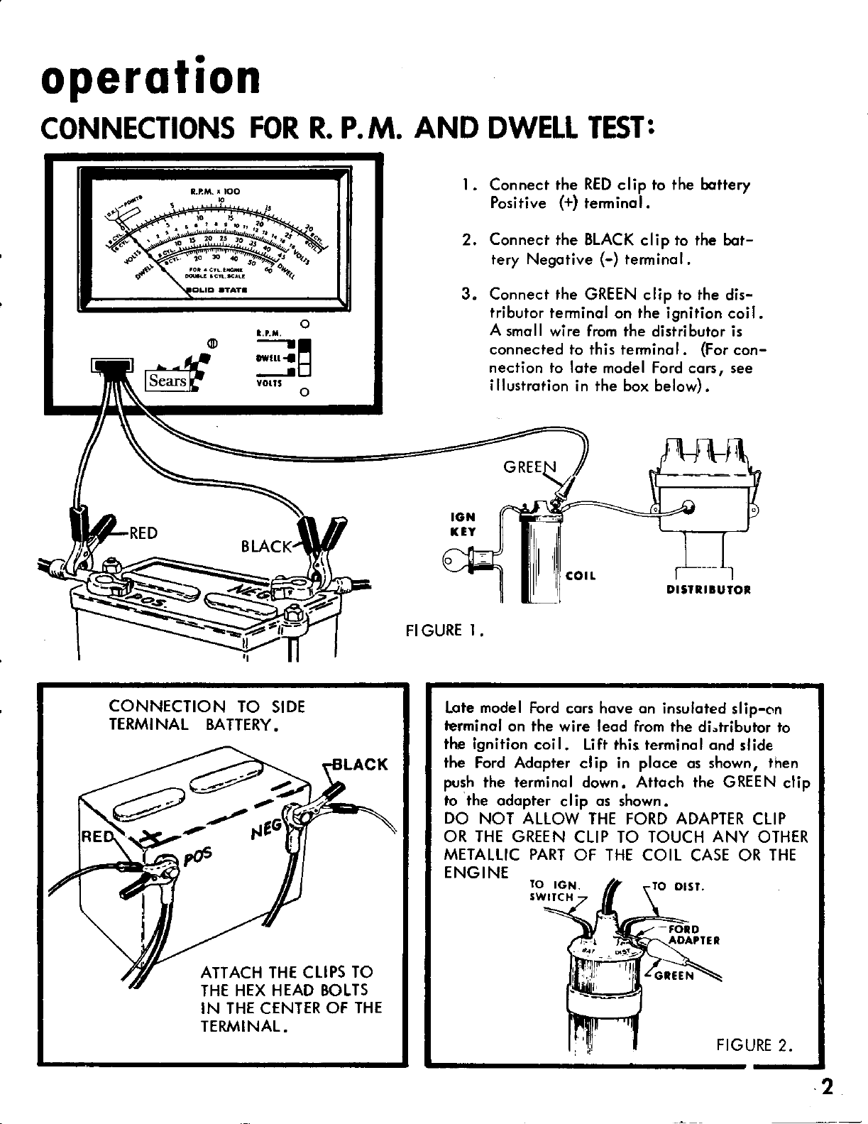
Connecf the test leods os ehown in FIGURE I
on Poge 2.
NOTE: Voltoge reodings con olso be mode
with the GREEN leod connecied os shown in
FIGURE 'I .
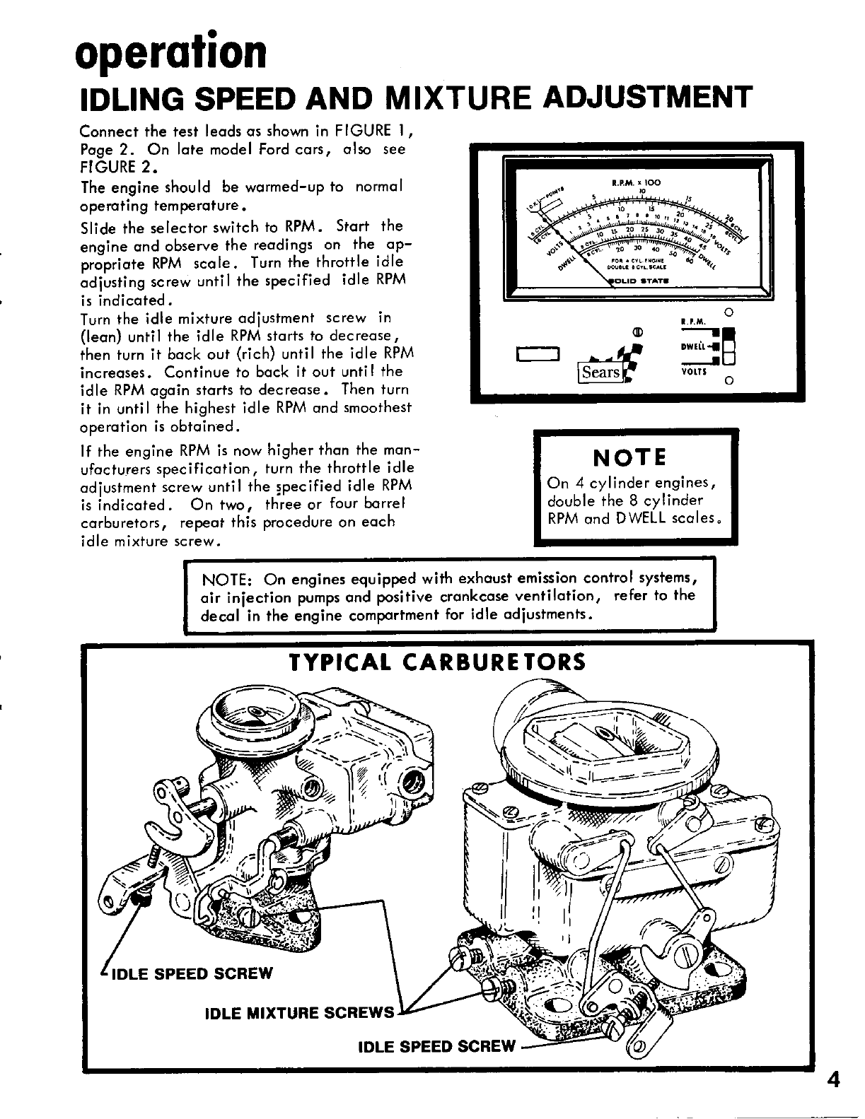
Slide the selector knob to the VOLTS position.
Observe voltoge reodings on the 0-16 D. C.
VOLTS scole. Eoch division on this scole rep-
resents .2 volts.
CONSULT THE OPERATING MANUAL
OF THE VEHICLE BEING TESTED FOR
SPECIFIC VOLTAGES AND TEST
PROCEDURES:
The following iniormotion wi ll serve os o
generol guide for moking chorging system
tests.
BEFORE MAKING ANY ELECTRICAL
TESTS, MAKE THE FOLLOWTNG VISUAL
CHECKS:
Check the fon belt -- it should be tight ond
in good condition .
Check the generotor or olternotor pulley ond
mounting bolts. They should be tight.
/rr'loke sure thot the chorging syslem wiring ond
the bottery cobles ore in good condition ond
thot connections ore fight. lvloke sure the
boftery is cleon ond thof the liquid level in
eoch ce I I is obove the plotes. When woter is
odded to ony cell, chorge the bottery ot 15 -
25 omps for 15 minutes to mix the woter with
electrolyte.
The engine ond oll ports of the chorging
system should be ot normol operoting temper-
oture before moking ony electricol tests. lf
ihe engine is cold, operote the engine ot idle
for 15 minutes before moking ony tests.
ENGINE OFF
Wifh the engine off, o 12 volt bottery will
normolly reod between 12.2 ond 12.8 volts
ond o 6 volt bottery will reod between 6.1
ond 6.4 volts. Reodings higher thon these
figures indicote fhot the boitery is holding
o surfoce chorge. lf the heodlights ore turned
on for o few minutes or fhe engine cronked,
the surfoce chorge wi I I be disipoted.
STARTING
A fully chorged l2 volt bottery should not
drop below 9.6 volts ond o 6 volt bottery
should not drop below 4.8 volts when cronk-
ing. Reodings below these figures indicote
trouble in the bottery or storting circuit ond
fhe bottery ond storting circuit should be
checked corefully to defermine fhe couse.
CHARGING
Stort the engine .With the engine wormed up
ond running ot 1500 RfM, the rneter should
reod within the specified volfoge ronge for
fhe vehicle. Reodings lower thon specified
indicote either o worn out or dischorged bot-
teryrdefective generotor or defective or im-
properly odiusted vo lfoge regu lotor. Reodings
higher fhon specfied indicofe o defective or
improperly odiusted voltoge regulofor or ex-
cessive resistonce in the voltoge sensing leod. 6
operolion
TIMING
The engine should be timed ot eoch tune-up
ofier the idle speed, mixture ond dwell od-
iustments ore mode ,
Check your owners mqnuol for the locotion
of the timing morks ond the timing specifico-
tions. Then use o timing light to time rhe
engine to specificofions.
PRETIMINARY
l. Check the distributor dwell ongle ond od-
iust to the monufocturer's specificotions,
if necessory, befoie fiming the engine.
Check the idle RPM ofter the engine is iimed
ond re-odiust fo the monufocfuren specifico-
tion if necessory.
Connect the Timing Light to the bottery ond
engine in occordonce with the instructions
supplied with the i nstrument.
NO.1 CYL INDE R
2. Cleon the dirt from fhe iiming morks.
3. Disconnect the vocuum odvonce line
the distributor ond seol the end of the
with fope or o plug.
4. Connect o iochometer to the engine ior
id le speed setting .
ENGINE TIMING
t. Siort the engine ond ollow it to worm up.
Affer the engine is worm, operote it ot
idling speed or the RPM specified in the
vehi cle monuol.
Aim the iiming lighf ot the timing morks,
press the switch fo operote the timing Iighr
ond observe the timing mork. The position
of the timing mork must ogree with the
monufocturer's specificotion. lf ii does
not, reset the timing os follows:
Loosen fhe distribuior hold-down clomp
JUST enough to permit rototing the dist-
ributor body by hond .
5. Slowly turn the distribuior in the correct
d ire ction:
A. Agoinst lhe rotor rototion to odvonce
ihe iiming.
B. Wiih the rotor rotqtion io retord ihe
timing.
6. When the specified mork is in line wiih
the timing line, securely iighten the
distributor ho ld-down c lomp.
7. Recheck the iiming.
NEGAT IVE
from
line ADAPTT R
_)
\
)
J.
4.
7
FREQUENTTY USED TUNE. UP INFORMATION
VEH ICLE IDL E
RPM DWELL
ANGLE TIMING SEARS
TUNE-UP
KIT #
SPARK
PLUG
TYPE
noles
GUARANTEE
We guorontee this Seors Automotive Test lnsfrument to be free from defects in moteriol ond
wo*monship. Should o defecl occur wiihin one (l) yeor from dote of sole, simply retum
the instrument to us ond we will repoir it, free of chorge.
This guoronlee does not cover domoge resulfing from misuse, obuse or occidenl.
Sears, Roebuck and Co.
8
a
repoir porls
$
(\l
cr!
I
J
llt
o
o
-
4
ul
F
lrt
=
t-
J
o
4
ut
F
ut
-
o
E
I
F
J
J
llt
3
o
I
o
repoir porls
ow r u/rlc HoMETEn/ volrmETER MODEL t61.2124
AIJTCl
BATTEFIY
+
FIEE! CLIF
Elts?FltEluToFl
G;FIEEN CLIP
AUTcl
BATTEFIY
BLACK CL
t3 14 t5
t6 23
IF 26
27-PFIINTED ClFlcUlT
EIclAFIE!
KEY
NO PART NO. DESCR]PTION KEY
NO PART NO. DESCR,IPT ION
I
2
3
4
5
6
7
8
9
l0
ll
t2
l3
l4
l5
l6
38-201
260-123
260-lM
38-205
t 000- I09
100-272
180-293
1000-48
1000-r03
320-107
290-1M
1000-l l0
25-170-87
33-r09
25-170-81
2l-l06
Coble Assemblv
Screw, # 4-40 " l/l tzl
Screw #642 x \/a @)
Sockei Flousing Assembly
Mefer Assembly
Froni Ponel
Adoptor Spring, Spork Plug
Ford Coil Adoplor
Hond le & Cose Assembly
Lock Wosher
Nuf Hex
Printed Circuit Boord Assembly
Resistor, 3.9K Ohm, l/2 W ,lek
Diode, Silicon
Resistor,2.2K Ohn.,l/2W - lCP/o
Copocifor, 0. I MFD - 250 V
17
l8
l9
20
2l
22
23
24
25
26
27
2s-170-73
25-170-63
33- t 08
33-t l0
27-112
700-109
2s-171-101
27-115
2 t-105
2l-118
400-221
2-1215
Resistor, lK Ohm, l/2W - l@/"
Resistor,390 Ohm, 1/2 W - l0lo
Tronsistor - NPN
Diode, Zener 6.2 V, 400 MW
Potenfiometer, l0K Ohm, l/2 W
Switch Se lecfor
Resistor, l5K Ohms,l,/2 W - l0lo
Potentiometer, 500 Ohn', l/2W
Copocitor, 500 MFD - 2-l/2V
Copociior, 1.0 MFD - 25 V
hinted Circuit Boord
(Not lllusfroted)
Monuo I , Owners
(Not lllusfroted)
ro
Sears
ouuners
monuol
DWEtt
TACHOMETER
VOTTMETER
MODE L NO.
l 61. 2124
SEARS SERVICE
IS AT YOUR SERVICE
WHEREVER YOT' IIVE
oR rvlovE
IN THE U.S.A.
I{OW TO ORDER
REPAIR PARTS
The Model Number will be found on the ponel below the meter.
Alwoys mention the Model Number when reguesling service or
repoir porls for your Dwell Tochometer.
All ports listed herein moy be ordered through SEARS, ROEBUCK
AND CO. Wren ordering ports by moil, selling prices will
be furnished on request or poris will be shipped ot prevoiling prices
ond you will be billed occordingly.
WHEN ORDERING REPAIR PARTS,
FOLLOWING INFORM,ATION AS
I . The PART NUMBER
2. The MODEL NUMBER
161 .2124
ALWAYS GIVE THE
SHOWN IN THIS LIST.
The PART DESCRIPTION
The NAME OF ITEM:
DWELYTACHOMETEB/
VOLTMETER
3.
4.
Your Seors merchondise tokes on odded volue when you discover
thqt Seors hos over 2,,000 Service Units fhroughout the country.
Eoch is stoffed by Seors-troined, professionol technicions using
Seors opproved ports ond methods.
Sears, Roebuck and Co., Ctricag(), Ilt. 6C)(jC)7 U.S.,.\.
and Sirnpsons Sears Lirnitcd, T()r'()r)t()
Printed in U. S. A.

Other Sears Measuring Instrument manuals

Sears 161.2161 User manual

Sears

Sears 161.2161 User manual

Sears 161.216300 User manual

Sears

Sears 161.216300 User manual

Sears 161.216500 User manual

Sears

Sears 161.216500 User manual

Sears 934.36390600 User manual

Sears

Sears 934.36390600 User manual

Popular Measuring Instrument manuals by other brands

Oval PG30 instructions

Oval

Oval PG30 instructions

Hanna Instruments GroLine HI98168 instruction manual

Hanna Instruments

Hanna Instruments GroLine HI98168 instruction manual

Milwaukee MW14 user manual

Milwaukee

Milwaukee MW14 user manual

SPECS PHOIBOS Series user manual

SPECS

SPECS PHOIBOS Series user manual

janitza UMG 512 PRO installation instructions

janitza

janitza UMG 512 PRO installation instructions

PeakTech 1650 Operation manual

PeakTech

PeakTech 1650 Operation manual

Mediana i20 user manual

Mediana

Mediana i20 user manual

Cannon CAV 4.2 Operation manual

Cannon

Cannon CAV 4.2 Operation manual

Kobold OPT-Y24896/0001 operating instructions

Kobold

Kobold OPT-Y24896/0001 operating instructions

Fotric 226B Quick start manual

Fotric

Fotric 226B Quick start manual

GREISINGER G 1400 Series Quick reference guide

GREISINGER

GREISINGER G 1400 Series Quick reference guide

Endress+Hauser EngyCal RH33 Brief operating instructions

Endress+Hauser

Endress+Hauser EngyCal RH33 Brief operating instructions

SICK GRL18V operating instructions

SICK

SICK GRL18V operating instructions

Claas ba-1381 Operation instructions

Claas

Claas ba-1381 Operation instructions

Ametek ORTEC 428 Operating and service manual

Ametek

Ametek ORTEC 428 Operating and service manual

Blue-White industries Sonic-Pro S6A Series operating manual

Blue-White industries

Blue-White industries Sonic-Pro S6A Series operating manual

Biospace InBody230 Install manual

Biospace

Biospace InBody230 Install manual

ABB C11 user manual

ABB

ABB C11 user manual

manuals.online logo
manuals.online logoBrands
  • About & Mission
  • Contact us
  • Privacy Policy
  • Terms and Conditions

Copyright 2025 Manuals.Online. All Rights Reserved.