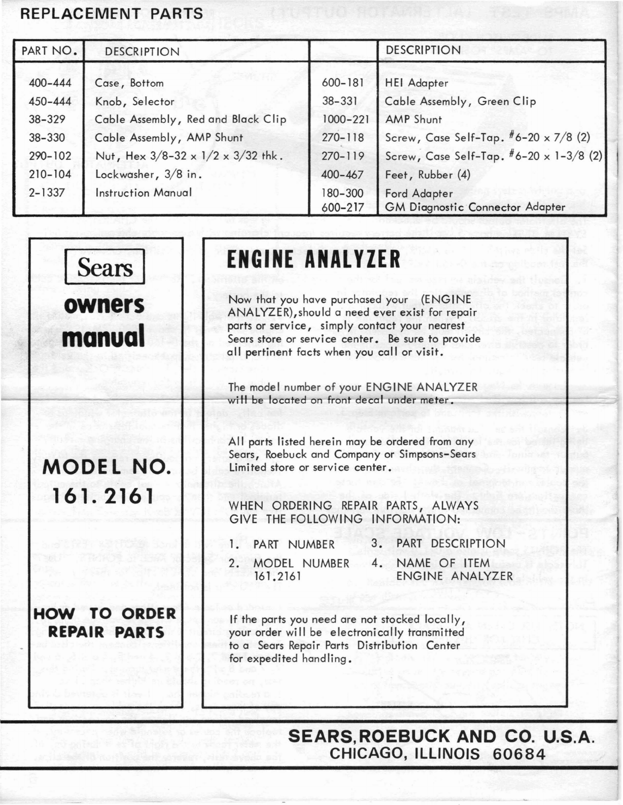
Sears 161.2161 User manual

owners manual
ENGINE ANALYZER
MODEL
161.2161
FOR 12 VOLT IGNITION
SYSTEMS
IMPORTANT
The
information
in this manual will
serve
as
a
general
guide
for
engine
tune-up
and
charging
system tests
and
adjustments.
CONSULT
TH-E
OWNERS
MA~UAL
OF
TffE
VEHrCtf
BEI~
TtSTEDl"'"'oO;;-:1~:::;?-i'~~~--'
FOR
SPECIFIC
TUNE
-UP INFORMATION
AND
TEST
PROCEDURES.
THE
MANUFACTURERIS
SPECIFICATIONS AND
TEST
PROCEDURE
FOR
ADJUSTING
DWELL
ANGLE,
IDLE
SPEED
AND CHARGING
SYSTEM
OUTPUT
SHOULD
BE
FOLLOWED.
FOR
SAFE OPERATION
Be
careful
when
testing
an
operating
engine
--
stay
away
from
the
fan
blades,
drive
belts,
high
voltage
spark 'plug
wires
and
hot
exhaust
manifold.
.
Operate
the
vehicle
in a
well
ventilated
area
to
avoid
•
danger
of
carbon
monoxide
poisoning.
I
[
PRINTED
IN
U.S.A.
_
• <
SEARS,ROEBUCK
AND
CO. U.S.A.
CHICAGO, ILLINOIS
60684
2-13370

-
I
ZERO ADJUSTER. Before
the
con-
nections
are
made,
if
the
pointer
is
not
on
zero,
rotate
adjuster
slowly
with
a
screwdriver
until
pointer
is
on
zero.
1.
Connect
the
RED
clip
to
the
bat
e .
Positive
(+)
terminal.
2.
Connect
the
BLACK
clip
t· the:
,t-
tery
Negative
(-
termin
3.
Connect
the
GREEN
ell
tributor
connection
on t
coi
I.
For
connections
to
Ford
cars,
Delco
High Energy
Ignition,
Ford
transistor
ignition
and
Chrysler
transistor
ignition,
see
Figs.
2,
3,.4,
5
and
6.
I
~~.-"::::;;;~,.---
FUNCTION
SELECTOR'
KNOB
FIGURE 1
AMPS SHUNT
Not
used for these
tests -See
page
6
for
amp
test
con-
nections.
COIL
CONNECTIONS
FOR
RPM,
DWELL, VOLT
AND
POINTS TESTS
SLIDE
SWITCH
KNOB
TO
-
"OTHER
TESTS
"
POSITION
TACHOMETER
CONNECTION
TO GENERAL MOTORS CARS
WITH
DIAGNOSTIC
CONNECTOR
AND DELCO HEI
TACHOMETER
CONNECTIONS
FOR GENERAL
MOTORS
CARS
WITH
DIAGNOSTIC
CONNECTORS
To
make
RPM
tests,
locate
the
Engine
Elec-
trical
Diagnosis
Connector
(usually
near
the
left
front
fender)
open
the
cover
and
insert
a
spade
terminal
in
socket
No.6.
Connect
the
GREEN
clip
to
the
spade
terminal.
The
RED
clip
must
be
connected
to
battery
POS.
(+)
and
the
BLACK
clip
to
battery
NEG.
(-).
DELCO
HIGH
ENERGY
IGNITION
4
CYL,
AND
IN-LINE
6
CYL.
HEI
GR~EN"
~
CL~
HEI
ADAPTER
INCLUDED
01
---~
~-~
',,~
...
v - a
ENGINE
HEI
FIGURE
3.
CONNECT
GREEN
CLIP
TO
THIS
TERMINAL
On
4
cylinder
ond
in-line
6
cylinder
engines
with
0
separote
coi
I,
connect
the
GREEN
clip
to
the
open
TACH
ter-
minal
as
indicated.
:I
~
"
::
,0
On
the
integ,ol
coil
v-a
HEI,
slide
the
•
~
I"
1/1
l'
.-
odapterontothe
TACHterminalasshown.
~L
t
1:
At
[7
Then
connect
the
GREEN
clip
to
the
• -
"'"
I •
cl
adapter.
The
RED
and
aLACK
clips
ore
......
:';::~
'/
connected
to
the
battery
Positive
and
1'/
Negative
os
shown
in FIGURE 1
'/'/
,.-
'/
GREEN
CLIP
FIGURE
2.
1

TACHOMETER
CONNECTION
TO FORD
AND
CHRYSLER TRANSISTOR
IGNITION
SYSTEMS
AND
LATE
MODEL
FORD STANDARD
IGNITION
On
Ford cars,
Ii
ft
the
dis-
tributor terminal and slide
the Ford Adopter
clip
in
place
as shown, then push
the terminal down on
it.
Remove
when the tests are
finished.
Connect
the
GREEN
lead
to
the
negative
ter-
minal
of
the
ignition
coi
I.
Connect
the
RED
and
BLACK
clips
to
the
battery
Positive
and
Negative
as
shown in FIGURE
1.
CHRYSLER
IGNITION
GREEN
CLIP
I
FORD
IGNITION
Connect
the
RED
and
BLACK
clips
to
the
bat-
tery
Positive
and
Negative
as
shown in
FIGURE"
1.
On
1974 Ford transistor
ignition,
use
the
Ford
adapter
as
shown in FIGURE
6.
On
1975 Ford transistor
ignition,
connect
the
GREEN
clip
to the wire
terminal
on
the
DEC
side
of
the
coi I
as
shown
be
low.
FIGURE 4
..
FIGURE 5
COIL
FIGURE 6
POINT
.RESISTANCE
TEST-CONVENTIONAL
IGNITION
SYSTEMS
ONLY
Points
are
O.
K.
Turn
the
ignition
key
OFF.
Proceed
to
next
TEST.
5.
TEST
RESULTS
POII'JTS
POINTS
POINTS
POINTS
During
engine
tune-up,
this
test
should be
per-
formed
first.
1. The
engine
must be
OFF.
The
test
leads must
be
connected
as shown in
FIG.
1.
•
Se-t
the
slide
swi.-tch
knob to-OTHER
TESl-S
and
the
Function
Selector
Knob
to
POI NTS.
NOTE: Remove
the
distributor
cap
and
inspect
the
contact
points.
If
they
are
blued,
blackened,
or
pitted,
they
should
be
replaced.
Normal used
contact
points
are
light
gray
in
color.
If
the
con-
tact
points
pass
the
visual
in-
spection,
proceed
as follows:
3.
Replace
the
distributor
cap
and
REMOVE
THE
HIGH
TENSION
LEAD
FROM
THE
CENTER
OF
THE
DISTRIBUTOR CAP
AND
GROUND
IT
BY
PLACING
THE
LOOSE END
SO
IT
TOUCHES
THE
ENGINE
OR
FRAME.
NOTE: When
testing
a
vehicle
with
dual
points,
alternately
block
one
set
of
points
open
with
a
piece
of
in-
sulating
material
while
the
other
set
is
being
tested.
4.
TURN
THE
IGNITION
KEY
ON.
If
the
meter
reads
near
full
scale
right,
the
points
are
open.
Crank
the
engine
with
the
igni-
tion
key
or
an
external
starting
switch
a
fraction
of
a
revolution
at
a
time
until
the
meter
reads
in
the
left
hand
area
of
the
scale.
The
points
are
now
closed.
The
points
may be
defective
or
the
following
faults
may
exist:
Poor distributor
ground.
Poor
connection
on
the
primary
lead
from
the
distributor
to
the
ignition
coil.
Defective
distributor
lead.
Misaligned
points.
Correct
the
defect,
and
repeat
the
test.
2

POINTS-DWELL TEST AND
ADJUSTMENT
15
20
25
30
~V:~~:"~~
10
\ l IILI I I
50
5
o
aCYL
0
30
50
70
60
aCYL
0
E
6CYL
~'\I"111"111j1ll1~
6CYL
'E
L
4CYL
4CYL
L
1/8"
ALLEN
WRENCH
B.
Raise
the
metal
window
and
turn
the
point
adjusting
screw
with
an
1/8"
Allen
wrench
until
the
dwell
reading
is
the
same as
specified
by
the
manufacturer.
(FIGURE 7 )
On
engines
that
have
non-window
type
distri-
butors,
adjust
dwell
as
follows:
1.
Remove
coil
wire
from
center
tower
of
dis-
tributor
cap
and
ground
the
wire
by
p!acing
tne
loose
end
so
it
touches
the
engine
or
frame.
2.
Remove
the
distributor
cap
and
rot~.
5.
To
adjust
dwell,
loosen
the
locking
screw
(s)
slightly
and
adjust
the
point
gap
according
to
the
procedure
outlined
in
the
vehicle's
service
manual.
There
are
anumber
of
mechanical
methods
for
adjusting
breaker
points.
Two
typical
methods
are
shown in FIGURE
8.
Tighten
locking
screw,
and
recheck
dwell
while
crank-
ing
engine.
Repeat
procedure
if
necessary.
6.
Reassemble
distributor
and
recheck
dwell
read-
ing
with
engine
operating
at
idle
speed.
Repeat
4
and
5
if
necessary.
3.
Connect
a
remote
starter
switch
to
test
vehicle
or
have
an
assistant
crank
the
engine
for
you.
4.
With
ignition
switch
on
and
engine
cranking,
observe
reading
on
the
Dwell..:s:..;:c:.;:a.:le,:;.:.:-
_
Check
the
owners
manual
or
engine
compartment
decal.
Follow
instructions
regarding
vacuum
line
or
advance-
retard
solenoid
connections.
Vacuum
line
must
be
discon-
r:...~'\~"
nected
from
distributor.
~)
),.,
'
~
~"II'I
~
§!;,
11l1ii~~\1
1111
11
"\\
PLUG END
OF
VACUUM
LINE
Connect
the
tester
as s
own
in FIGURE
or
6.
Set
the
slide
switch
knob to OTHER
TESTS
and
the
Function
Selector
Knob
to
DWELL.
Operate
the
engine
at
idling
speed
and
observe
the
Dwell
reading
on
the
scale
that
corresponds
to
the
number
of
cylinders
in
the
engine
being
tested.
If
the
dwell
reading
is
higher
or
lower
than
the
manufacturer's
specification:
1.
On
Delco-Remy
distributors
with
a
sliding
metal
window
in
the
cap:
A.
Operate
the
engine
at
idle
RPM.
NOTE:
This
test
and
adjustment
is
performed
on
cars
with
conventional
ignition
systems
and
breaker-point
transistor
ignition
systems.
It
is
not
used
on
cars
equipped
with
electroni
c
igni-
tion
systems
that
do
not
have
breaker
points.
SLOTTED HOLE
FIGURE
8.
ADJUSTMENT
LOC
KING
SCREW--_-..::::;6Z..I
TYPICAL
DISTRIBUTOR
BREAKER
POINT
CONSTRUCTION
3
NOTE:
It is
important
to
recheck
the
ignition
timing
every
time
the
points
are
adjusted.

DWEll
VARIATION
TEST
Check
the
owners manual
or
engine
compartment
decal.
Follow
instructions
regarding
vacuum
line
or
advance-retard
solenoid
connections.
Vacuum
line
must
be
disconneded
from
distributor.
Increase
the
engine
speed
from
idle
to aminimum
of
1500
RPM
and
then
reduce
it
back
to
idle.
Watch
the
dwell
reading
during
this
procedure.
If
the
dwell
variation
is
more
than
3
degrees,
check
for
wear
in
the
breaker
plate
or
wear
in
the
distri-
butor
shaft
or
bushings •
IDLING SPEED
AND
CARBURETOR
ADJUSTMENT
Start
the
engine
and
turn
the
idle
speed
screw
unti I
specified
idling
speed
is
indicated.
x100
14
(See owners
manua
I).
On
engines
without
exhaust
emmission
control
sys-
tems,
turn
the
idle
mixture
screw
in
(lean)
unti I
the
idling
speed
starts
to
decrease,
then
turn
it
back
out
(rich) just
until
the
idling
speed
reaches
amaximum. Further
richening
past
this
point
will
only-wos-te
ftte~.
lh-ts--s-heul~done
slewly
to
al
low
eng
i
ne
speed
to
stab
iii
ze
•
NOTE:
On
multi-barrel
carburetors,
repeat
this
procedure
on
each
idle
mixture
screw
until
the
highest
idling
speed
and
smoothest
operation
is
obtained.
If
the
engine
idle
speed
is
now
higher
than
the
manufacturer's
specification,
turn
the
throttle
idling
adjustment
screw
unti
I
the
speci-
fied
idling
speed
is
indicated
and
readjust
the
mixture
screws
with
the
above
procedure.
TYPICAL CARBURETORS
10
12
B
o
RPM
x100
SOLIO
Connect
the
test
leads
as shown in FIGURE
1.
Set
the
slide
switch
knob
to
aT
HER
TESTS
and
the
Function
Selector
Knob
to
the
RPM
position
that
corresponds to
the
number
of
cylinders
in
the
engine
being
tested.
.---0
serve-tne
test
readings
onthe
RPM
x100
scale.
The
engine
should
be
at
normal
operating
temper-
ature
for this
test.
Many
cars
built
in 1970
and
later
have
idle
mixture
screw
limiter
caps
that
restri
ct
adjustment.
On
these
cars
the
carburetor
should be
adjusted
according
to
the
procedure
in
the
manufacturer's
service
manual.
NOTE:
On
engines
equipped
with
exhaust
emission
control
systems,
air
injection
pumps
and
positive
crankcase
ventila-
tion,
refer
to
the
decal
in
the
engine
compartment
or
the
owners
manual
for
idle
adjust-
ment
specifications.
IDLE
MIXTURE
SCREWS
IDLE
SPEED
SCREW
...
----------
.....
--------------------4

VOLTS -PRELIMINARY CHECKS
The VOLTS
position
is used
to
test
the
cranking
and
charging
systems in
the
vehicle.
CONSULT
THE
OPERATING MANUAL
OF
THE
VEHICLE BEING
TESTED
FOR
SPECIFIC VOLTAGES
AND
TEST
PROCEDURES:
The following information
will
serve
as a
general
guide
for making
charging
system
tests.
Before making VOLTS tests:
Check
the
fan
belt--it
should be
tensioned
according
to
the
manufacturer's
specifications.
Check
the
generator
or
alternator
pu IIey
and
mounting
bolts.
They should be
tight.
CRANKING va
TS
TEST
1.
Remove
the
high tension
lead
from
the
center
of
the
distributor
cap
and
ground
it
by
placing
the
loose
end
so
it
touches
the
engine
or
frame.
2.
Connect
the
test
leads as shown in
Fig.
1.
Set
the
slide
switch
knob
to
OTHER
TESTS
and
the
Function
Selector
Knob
to
VOLTS.
3.
Operate
the
starter
for 10 seconds
and
ob-
serve
the
cranking
voltage
on
the
0-16
Volts
scale.
A
steady
reading
of
more
than
9.6
volts
indicates
that
the
battery,
cables,
and
starter
system
are
in
good
condition.
CHARGING
SYSTEM
VOLTS TEST
.
1.
Connect
the
test
leads as shown in
Fig.
1.
Set
the
slide
switch knob
to
OTHER
TESTS
and
the
Function
Selector
Knob
to
VOLTS.
Start
the
engine.
Allow
it
to
run afew
minutes
at
1500 to
2000
RPM.
Observe
the
reading
on
the
0 - 16 volt
scale.
The
pointer
should be
between
13.2
and
15.2
volts
with
or
without
headlights
and
5
Make
sure
that
the
charging
system
wiring
and
the
battery
cables
are
in
good
condition
and
that
connections
are
tight.
Make
sure
the
battery
is
clean
and
that
the
liquid
level
in
each
cell
is
above
the
plates.
The
engine
and
all
parts
of
the
charging
system
should be
at
normal
operating
temperature
be-
fore making
any
electrical
tests.
If
the
engine
is
cold,
operate
the
engine
at
idle
speed
for
at
least
15 minutes before making
any
tests.
4.
A
reading
below
9.6
volts
could
be
caused
by
~
a
battery
that
is
defective
or
not
fully
charged.
Fully
charge
the
battery
and
repeat
the
test.
If
the
reading
is
sti"
below
9.6
volts,
either
the
battery
or
starter
is
defective.
5.
A
fluctuating
voltage
reading
is
indicative
of
a
defect
in
the
starter
or
battery
or in
the
battery-starter
wiring
circuit.
Refer
to
page
6
(POINTS-LOW
VOLTAGE SCALE) for
trouble
shooting
voltage
drops in
the
battery-starter
wiring
circuit.
Replace
or
repair
any
defective
parts as
required
~
to
restore
cranking
system
to
proper
operation.
6.
Replace
the
high tension
lead
in
the
center
of
the
distributor
cap.
blower
motor
on.
Readings lower
than
13.2
indicate
either
aworn
out
battery,
defective
generator
or
alternator,
defec-
tive
or improperly
adjusted
voltage
regu-
lator.
Readings
above
15.2
are
indicative
of
a
defective
or
improperly
adjusted
voltage
regulator.
Replace,
repair
or
adjust
the
defective
part
as
required.

AMPS
TEST
(ALTERNATOR
OUTPUT)
REVERSE
CONNECTIONS
IF
METER
READS
BACKWARDS
OUTPUT
on
the
alternator.
Reconnect
the
Negative
cable
to
the
battery.
4.
Turn
off
all
lights
and
accessories.
Start
the
engine
and
rev
it
to
about
2000
RPM.
If
the
read-
ing
observed
on
the
0-160
AMP
scale
corresponds
to
the
alternator
output
specified
in
the
vehicle
service
manual,
the
alternator
is
O.K.
and
the
trouble,
if
any,
is in
the
regulator.
5.
=-If
the
outptJt j.s-be low-ra-t-ifl ,
cheek
fer I-eese
fan
belt,
defect
in
the
alternator
windings
or
diodes
or
higher
than
normal
resistance
in
the
cables
or
connections
in
the
charging
circuit.
6.
As
a
safety
precaution,
remove
the
battery
Negative
cable
before
you remove
the
shunt.
Attach
the
alternator
output
cable
to
the
output
terminal
and
then
re-connect
the
battery
Nega-
tive
cable.
The
alternator
output
should
be
checked
if
the
vo;tage
reading
was
below
13.2
in
the
CHARGING
SYSTEM
TEST
on
page
5,
or
if
the
battery
requires
frequent
charging
with
a
portable
charger.
Set
the
slide
switch
knob to AMPS. The
Function
Selector
Knob
can
be
at
any
position.
Observe
the
test
reading
on the
0-160
AMPS
scale.
1.
Consult
the
vehicle
service
manual
for
the
correct
method
of
disconnecting
the
regulator
in
order
to
check
the
alternator
output
without
the
regulator
in
the
circuit.
When
the
regulator
is
disconnected,
the
circuit
must be bypassed in
order
to
observe
alternator
output.
Consult
the
vehicle
service
manual for
correct
method
of
bypassing
the
regulator
circuit.
2.
Remove
the
Negative
cable
connection
on the
-.battery
is
wiII-e
Ii
mi
nate-t-he
danger
of-shoF-t-i-Ag
the
battery
with
the
tooIused
to
perform
Step
3.
3.
Consult
the
service
manual
for
the
vehicle
being
tested
for
the
location
of
the
alternator
output
terminal
and
remove
the
cable
from
the
output
terminal.
Connect
the
shunt
between
the
cable
and
terminal
as
shown.
Be
sure
these
connections
are
tight.
The
slotted
side
of
the
shunt should be
connected
to
the
Positive
terminal
POINTS-
LOW VOLTAGE SCALE
The POINTS
scale
is
also
a
0-1.0
volt
scale.
This
scale
is useful for
checking
voltage
drops
in
the
vehicle's
electrical
system.
POINTS
NOTE:
USE
GREEN
AND
BLACK
CLIPS· FOR
THIS
TEST
POINTS
Set
the
slide
switch
knob to OTHER
TESTS
and
the
Function
Se
lector
Knob
to
POI
NTS.
Use
the
GREEN
and
BLACK
clips
for
these
tests.
The
RED
clip
is
not
used.
Corroded
or
loose
connections
and
frayed
or
bro-
ken
cables
can
cause
excessive
voltage
drops in
the starting
circuit
which
can
cause
hard
starting.
To
test for these
conditions,
connect
the
clips
be-
tween 1
and
2,
2
and
3,
4and
5,
5and
6,
6and
7,
7
and
8with
the
starter
turning.
During this
test,
no
reading
should be higher than
.1
volt.
If
areading higher
than.
1
volt
is observed during
any
of
these
tests,
check
the
cable
or
connections
involved,
clean
and
tighten
the connections and
replace
the
cables
or
solenoid when
necessary.
If
the meter reads to the
right
of
zero
during
any
of
the
above
tests,
reverse the position
of
the
clips.
6

REPLACEMENT
PARTS
PART
NO.
DESCRIPTION DESCRIPTION
400-444
Case,
Bottom
600-181
HEI
Adapter
450-444 Knob, Selector 38-331 Cable Assembly, Green C
Ii
P
38-329 Cable Assembly,
Red
and Black Clip 1000-221
AMP
Shunt
38-330 Cable Assembly,
AMP
Shunt 270-118 Screw, Case
Se
If-Tap. #6-20 x
7/8
(2)
290-102
Nut,
Hex
3/8-32
x
1/2
x
3/32
thk.
270-119 Screw, Case Self-Tap.
#6-20
x
1-3/8
(2)
210-104 Lockwasher,
3/8
in.
400-467
Feet,
Rubber
(4)
2-1337 Instruction Manual 180-300
Ford
Adapter
(>00-217 GM DiagnosticConnector Adapter
ISears I
owners
manual
ENGINE
ANALYZER
Now
that you have purchased your
(E
NG
I
NE
ANALYZER),should aneed ever exist
for
repair
parts or
service,
simply contact your nearest
Sears store or service
center.
Be
sure to provide
all
pertinent facts when you call or
visit.
The
model number of your ENGINE
ANALYZER
lo---I----------lI--I--wfV+tt-"h
u,e-~ocate
on
front decaIunder meter. !
MODEL
NO.
161.2161
A
II
parts listed herein
may
be ordered
from
any
Sears, Roebuck and Company or Simpsons-Sears
Limited store or service
center.
WHEN
ORDERING
REPAIR
PARTS,
ALWAYS
GIVE
THE
FOLLOWING INFORMATION:
1.
PART
NUMBER
2.
MODEL
NUMBER
161.2161
3.
PART
DESCRIPTION
4.
NAME
OF
ITEM
ENGINE ANALYZER
HOW
TO
ORDER
REPAIR PARTS
If
the parts
you
need are not stocked loco IIy,
your order
wi"
be electronico
IIy
transmitted
to aSears Repair Parts Distribution Center
for
expedited handling.
SEARS,ROEBUCK
AND
CO. U.S.A.
CHICAGO, ILLINOIS
60684
Table of contents
Other Sears Measuring Instrument manuals