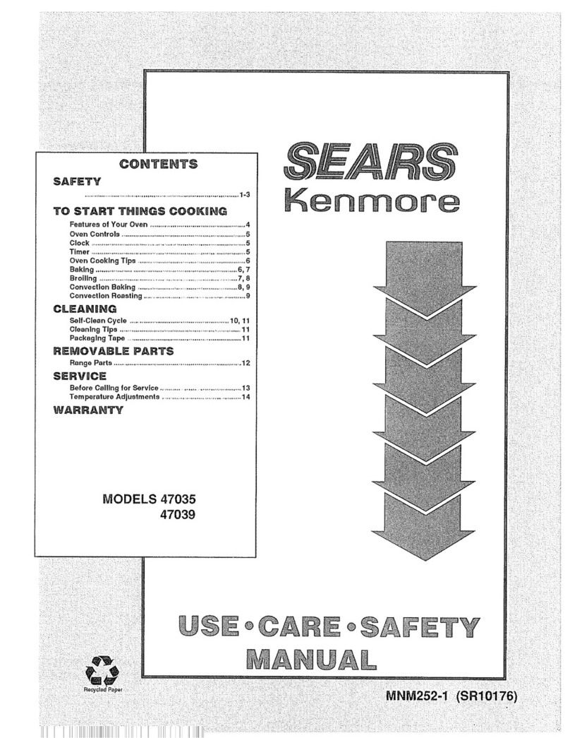
Sears 911.47890C2 User manual

lHi;
tLtlr
.!
Department 7314. Tbronto
TECHNICAL FLASH
78
r
989
SER-VT CE IVIA}{[TIA]-
EI-ECTR.- C Bt'I I.T- II{I
IVIODEI,S :
9f-1 - 47 890C2
91f_ - 47 89f-C2
OVEI.T

27
" ELECTRI
CSELF-
CLEANI
NG-IJALL
oVEN
?78.47890C2
- l{hite
278.47891C2
- Black
RATINGPLATE
TheRatingPlate is locatedbehindthe oven
dooron the front frame
of the oven.
TOSETTHECLOCK
1. Push
CL0CKbutton.
2. Turn
SETknobto cornecttimeof day.
TOSETI'IINUTE/SECOND
TII,IER
I. PushTll'lER
button.
2. Turn
SETknobto desiredamountof time
(upto t hoursand59minutes). Timer
w'il'l beginto count
downwithin a few
seconds.
3. }lhentime is upthe End-of-CycleTone
(3 'long
beeps)wi11soundanddisplay
will return to t'imeof day.
N0TE:The
control displays
bothminutes
andseconds
for the first hour.
TOCANCELTHE
TII'IER
Pushandhold TIl,lERbutton for three
seconds.
TOBAKE
1. Push
the BAKEbutton.
2. Turn
the SETknobuntil desired
temperatureis displayed.
A onesecondbeepwi11 soundwhenthe oven
has
preheated
to andstabiIizedat selected
temperature.
3. l'lhenf inishedbak'ing
push
CANCEL.
-I-

1.
2.
TO
BROIL
1. Push
BR0IL
button.
2. TurnSET
knob
until your choiceof HI
BR0IL
or L0BROIL
is visible in the
di
spl
ay.
3. llhen
finished push
CAI{CEL.
TO
USE
AI'TO}IATIC
OYEIITII,IER
Push
C00K
TI}IE
button.
Turn
SET
knob
to set length
of baking
time. ,
3. Push
EA|G
button.
4. Turn
SET
knob
to set desired
temperature.
llhen
cook
time is complete
End-of-Cycle
Tone
will sound
and
theoven
will sirut
off.
TO
DISPLAY
START
OVEII
TII,IER
l. Push
C00K
TII|E
button.
2. Set
baklng
time
with SET
knob.
3. Push
STOP
TlitE
button.
4. Turn
SET
knob
to timeof day
baking
should
be
complete.
5. Push
BAIG
button.
6. Turn
SET
knob
to desired
temperature.
llhen
cook
tlme is complete
End-oi-Cycle
Tone
will sound
and
theoven
will sirut
off.
HO}I
TO
CHANGE
A PROGRAI'I
l{hen
a function
has
been
entered,
you
can
recall what
has
been
programed
bypushing
thecorresponding
function
button.
'fne
messages
in thedisplay
show
you
which
function
is currently
being
displayed.
l{hile
the function
is dispiayed,
you
can
change
it with the SET
knob. you
can
change
any
prograrmed
function
at any
time.
-2-

TOI{E
End-of-Cvcl'e
Tone
(3 long
beeps
- one
secondon, onesecond
off): shows
that a
tined oyen
operation
hasreached
ST0p
TIiIE
or that the lllnute/Second
Timer
hascounted
down.
Attention
Tone
(series
of short
beeps,
l/4
second
on, l/4 second
off, until proper
responss
is given): will sound
if ovenhas
onlybeen
partlally progranmed.
For
example,
if you
have
selected
a cooktime
but notenperature,
you
will hear
the
Attention
Toneuntll you
select a
temperature
or push
ovenCANCEL.
Notificatlon
Tone
(single,
one-second
beep):
indicates
oven
hasstabilized
at
selected
temperature.
KevTone
(single
1/10
second
beep):
sounds
whenany
button
is pushed.
Function
ErrorTone
(series
of veryrapid
beepg
, l/8 secondon, l/4 second
off):
displaywill shc a failure code. Cancel
Functlon
ErrorTone
bypushing
the oven
CAI{CELbutton. If the Function
Error Tone
starts again
(after about
15seconds),
call
for serYice. Dlsconnect
the range
electrical supplyto stop
the tone.
If the functlon
error occurred
whileyou
were
progranning
the Electronic
Control,
push
the ovenCAI{CEL
buttonand
try again.
ToCancel
theTone...Ifyou
don'twantan
audibletone
when
you
push
a button,
you
caneliminatethe Key
Tone
bypushing
and
holdingthe ovenCAIICEL
button
until you
heara short beep
(ln approximately
two
seconds).
To
actlvatethe tones
again,
push
andhold the oven
CAI{CEL
button
once
moreuntil you
hear
a short beep.
Canceling
or actlvatlng
thetones
should
only bedonewhen
there is nooven
operation
prograrmed.
Pushingthe ovenCAilCEL
button
will clear
all functionsexcept
the Clock
and
ilinute/SecondTimer.
-5-

SET
THE
OVEil
FOR
CLEANITIG
l. Push
the CLEAII
button.
2. Turn
SET
knob
in theclockwise
di
recti
on.
Display
will read
3 hour
30min.
NOTE:
Youcan
find out when
the clean
cycle
will befinished
by
pushing
the STOP
TII|E
button.
The
word
D00R
is displayed
when
you
try to
set a clean
cyclewith the door
open
or
when
the oven
temperature
is too high.
TOSET
A DELAYED
START
l. Push
ST0P
TI}IE
button.
2. Turn
SET
knob
to timeof day
when
you
wish
cleaning
to be
completed
(must
be
more
than
3 l/2 hours
later than
current
tine of day.)
3. Push
the CLEAT{
button.
4. Turn
SET
knob
in theclockwise
directi
on.
Thewords
DELAY
CLEAII
will be
on in the
display
until the
clean
cycle
starts.
After the clean
cyclestarts, the word
CLEAII
will be
on
in the
display.
NOTE:
During
a delayed
self-clean
operation
you
can
find out when
the oven
turns
on
by
pushing
and
holding
theCLEAII
button.
-4-

TOSTOP
A CLEAII
CYCLE
1. Press
the ovenCAIICELbutton.
2. l{ait until the ovenhascooled
below
locking tenperature
(about
20-30
minutes)
and
the word
L0CK
is off in
the display.
You
will not be able to open
the door right
away
unless the oventemperature
is at a
safe level. If youcannot
open
the oven
door irmedlately after the wordLOCK
goes
off, wait one
minute
and
try again.
II'IPORTAI{T
The
oven
doormust
beclosedand
all
controls must
be set correcily for the
clean
cycle to work
properly.
If the oven
door
is not closed,
the
D00R
is displayed
and
the oven
beeps
continuously.
Close
thedoor,
touch
and
begin
again.
word
CAI{CEL
OYEII
THERIIOSTAT
The
oven
tenperature
is presetat the
factorybut can
be
changed
bythe following
procedure.
To
AdjustTemoerature:
l. Push
the BAKE
button.
2. Selecta temperature
between
500.Fand
550'F
with the SET
knob.
3. Qulckly
(withln two
seconds,
before
the
BAKE
function
energizes)
push
and
hold
the BAIGbuttonfor about
5 seconds.
The
display
will show
number
of degrees
difference
between
the original factory
temperature
settlng andthe current
temperature
setting. If the oven
tenperature
has
neyerbeen
adjusted,
the
display
will read
00.
-3-

4. Turn
the SETknob
to adjust the
tenperature
in 5.Fsteps. you
can
raise
lt 35.For lower
it 35.F. A
minus
sign (-) before
the numbermeans
that the ovenwill be
cooler
bythe
displayed
anountof degrees. If the
control beepsand
flashes, push
the
CAIICEL
button andstart oyer.
5. lfhen
youhavemade
the desired
adJustnent,
push
the CL0CK
buttonto go
back
to the tlmeof day
dlsplay
or to
use
youroyen
asyou
would
normally.
t{0TE:The
adJustnent
descrlbed
above
will
not change
the self-clean
temperature.
-6-

IiISTALLATI0iI
At{D
RE!,|0VAL
1. IIISTALLATIOII
A. CABIIIET
CUI-OUT
Dll,lEllSIOilS
Thecut-out dimensions
are as shown.
B. CABIilET
CoI|STRUCTI0I{
REQUIRE}tEilrS
o The
cablnet
musthave
either a
solld botton
or tro runners,
on
14' (35.6
Cll)
centers,
capable
of
supportlng
150
pounds.
o 0ven
must
befastened
to cabinet
with screws
driventhrough
holes
provided
in the ovenfrane
ELECTRICAL
REQUIREIIEI{TS
Theelectrical service
must
be
a separate
branch,
three-wire,
60
Hertz,
single-phase
circuit, fused
at 20amperes.
The
electrical installatlon should
conform
to
the Canadian
Electrical Code
andsuch
local
regulations
as
might
apply.
ELECTRICAL
CON]IECTIOTIS
THEELECTRICAL
POIIER
TOTHE
OVEII
SUPPLY
LITIEIIUST
BESH['T
OFF}IHILE
LIIIE
COIIIIECTIOilS
ARE
BEIIIG
}IADE.
FAILURE
TO
DO
SOCOULD
RESULT
IN SERIOUS
II{JURY
()R
DEATH.
Install the fuse
panel
in an
adJoining
cabinet
(range
has
4 feet (1.2m)
of
conduit.
l{hen
maklng
the wlre connectlons,
use
the
entlre length
of conduit
provided.
THE
COi{DUIT
iIUST}IOT
BECUT.
Thebare
ground
wire 'in
theconduit
is
connected
to the oven
frame. Connect
the
otherendof this wire to a ground
screw
in
the fusebox. Awhlte
(neutral)
wire is
, connectedto the neutralbase
'inthe fuse
\- box. Connectthe other
wires
asshown
in
thediagram.
-7-
'
f,It,,,
:1
I
aI
]|Yj'MIN
tt6J cmt
LEAOS
IN6XFLEXIBLE
coNoutt
I
IN LINC CAELE
',
"rnL.*r'I
ON l.l" 1l$"$61111
|
CENTERS ''
f;:;;

2. REiIOYAL
A. REI,IOYE
SCREI{S
SECURITIG
OVEI{
TO
CABIflET
Lift oven
dooroff of hinges
to
lessen
the weightof the ovenandto
expose
the ovenmounting. Remove
the mountlng
screws
located in the
vertlcal trim pieceson either side
of the oven.
B. REI,IOYE
OYEIIFROII
CABII{ET.
OYEI{
LIGHT
BULE
Before
replacing
the bulb,disconnect
electric porer
to the rangeat the main
fuse
or circuit breaker
panel
or unplug
the
range
from
the electrlc outlet. Let the
bulbcool completely
beforeremoving
it.
Donot touch
a hot bulb
with a danp
cloth.
If you
do, thebulbwill break.
ToRemove:
Remove
the 3 screwsin the lamp
cover.
Detach
lanpcover
ring, crystal and
gasket
andrenove
bulb.
BAKE
&BROIL
Ui{ITSERYICE
RE}IOVE
POIIERFROIIRATIGE
BEFORESERVICING.
Thebakeand
broil units canbeserviced
fromthe front. Bothunlts use
straight
push
on
tenninals. Theclearance
hole
in
the ovenllner is verytight and
care
must
betakenin pulling
the unit into theoven
not to knock
the terminal
off. If this
happensthe unit mustberemoved
from
the
instal
Iati
on.
VIEW
FROT
REAR
OFRA}IGE
-8-

\_ ovEll
ASSEilBLY
Theoven
liner is held
in place
byfour
screws
and
a sean
clip that screwinto the
front frane. Toremove
or replace
the oven
liner, the product
must
first beremoved
from
the installatlon, al'ong
wtthall
components
attached
to the oven
llner.
REIIOYABTE
OYEI{
RACKS
AIID
GUIDES
Be
careful not to scratch
the oven
finish
when
installlng or removing
oven
racks.
Instal
I:
Putthe pegs
onthe endof the rack
guide
into the holes
in the oven
back.
Lock
the front hook
in the slot in the
oven
side.
To
l.
2.
3. Setthe raised back
edgeof the oven
racks
ona pair of rackguides
sothe
hooks
at the sidesof the rack run
underneath
the rackguides.
4. Push
the rackln untll you
reach
the
bunp
in the rackthen, llft the front
of the racka bit and
push
the rackall
theway
in.
ToRemove:
l. Pull theoven
rack
outthen
up
in one
moti
on.
2. Lift the front of the rack
guide
to
unhook
it from
the oven
wall and
pull
out.
UI{ER
\,
-9-

To
l.
RE}IOVABLE
OVENDOOR
The
oven
doorcanbe removed
for cleaning.
To Remove:
l. Open
the doorto the stop position and
grasp
the doorat eachside (see
iIIustration).
2. Lift the doorupa bit, then
pull
straight toward
you.
Repl
ace:
l'lakesure that hingearmsare in
position
B (stopposition)
Note: If a hinge
armsnapsinto
position A, it must
bemovedback
into
position B before
the door
canbe
replaced.
2. Carefully insert the hingearms
through
the openings
in the front frame
and
push
the door
into place
whileholding
the doorup.
3. l{hen
the bottomedge
of the door is
fl ushagai
nst the front frame, al
'l
ow
the doorto settle into place
DOOR
ASSEI{BLY
Thedoor
consistsof four pieces
of glass,
insulationretainer,
insulation,inner
glass
retainer,inner
liner, gasket,
inner
panel
and
handle.
ToService:
1. Handle,
frameand
outer
glass
(Fig. l)
o Removesix screwsfrom frame
and
separate.
2. Twomiddle
glasspanes,
insulation
retai
ner andinsul
ation (
F'i
g. I
)
o Removescrews
from
middle
glass
retainers
andlift out glass.
o Removetwoscrewsfrominsulation
retainer and
separatefrom
jnner
door
Iiner.
o Removefour screwsandretainers
frominner glass retainers and
remove
secondmiddle
pane.
c|roqs
l|tr
ru\
;E
-
l0-

D00RASSEI,IBLY
Cont.
3. Gasketand
Inner
Glass
(Fig. 2)
o Remove
eight screwsfrom inner door
paneland
separate
inner panelfrom
inner
doorliner.
N0TE: Outer door frameremovalnot
necessary
for gasket
removal
with inner
door panel removed. Theinner door
glass
is alsoaccessible.
DOORHINGE
Toservice:
1. Removesix screwsfromframe
and
separate
framefrominner doorliner.
2. Hingeis now
accessible
andcanbe
removedby removing
two screwsas
depictedin Fig. 3.
HIMiE
\
h e.3
-
11-

CONTROL
PANELACCESS
Method
I -
o
o
Method
2 -
Fromfront of oven
Removethe four Phil'lips screws
marked
"A"
in illustration.
l'love
panelassembly
downto
access
components.
From
top of oven
Removemounting
screws
securing
ovento cabinet.
l'love
ovenout of cabinet to gain
access
to screws
uBu
in
'illustration.
o Remove4 screws
marked
"B".
o Remove
top of control area.
Removalof Top
cover
permits
accessto
the folIow'ing
components:
l'lainRelay
Board
- locatedin
center
of cabinet
top andmounted
byplastic PCboard
stand-offs.
L2RelayBoard
- located
'inright
corner
andis mountedvertically
to controlhousingbyplastic PC
boardstand-offs.
l'lotori
zedLockl*lechan'ism
- Located
jn front right cornerarea.
Fan
- Locatedin right corner
and
is mounted
to the Control
Housing.
Thefan is wiredin serieswith
the terminal
switch. The
fan is
activated
whenthe thermal
switch
senses
temperaturesof 133'Fin
the control panel. The
fancan
come
onin Bake,Broil, or Clean
operation
andcancontinue
to run
after the ovenhas
turnedoff.
I
?.
3.
4.
7/ */
- -'?
^\<rr2'
'r
-:2
A
-12-

OVEN
CONTROL
SYSTE}I
I\- BASIC
SYSTEII.
EXPLAT{ATION
The
ovenis controlled by an ELECTRONIC
RAllcE
C0NTR0L
(ERC)
System. TheERC
function as a thermostat, selector switch
and
clock/timer. Thesystemconsists
of
the ERC,
tr{orelay circuit boards,
anover
temperature
sensor
anda motorized
door
lock mechanism.
\-
The
ERCis powered
by a step-down
transformer
which
is located
onone
of the
relay circuit boards. The
transformer
has
twosecondary
windings
providing
3.2 V.A.C.
filament
voltage
to light the ERC
display
and
21
V.A.C.
which
the control uses
to
power
the coiIs of the ovencontrol relays.
A total of 5 relaysare usedto control
bake,
broil anddoorlock operations. Two
relays control the BAKE
circuit, two
relays
control the BROILcircuit and
one
relay
controls the doorlock motor. Two
relays
areused
in eachheating
element
circuit to
removebothsideCof the 'line (Ll and
L2)
fromthe element
when
the oven
is OFF.
Thedoor 'lock
relay 'is usedto power
a door
lock motor
whichdrives anautomatic
door
'l
ockdevi
ce. Thedoor 1ock relay is
energ'ized
irmediatelywhen
self cleanjs
selected
andwill remain
energized
until
the clean
cycle hasended
andthe oven
has
cooled
to a safe temperature.
NOTE: When
power
is ini
ti a'lI
y appl
ied to
the appliance
or if power
has
been
'interrupted
for anyreason,
the
ERCwill cycle the automatic
door
lock thru a lock, thenunlock
cycle.
TheERCmonitors
the oventemperature
throughthe oventemperature
sensor. The
sensoris mountedon the rear wal
'l of the
oveninterjor. The
sensorfunctions
by
changingin electrical resistance
with
changesin oventemperature.TheERC
translatesthe changein sensor
resistance
into oven
temperature
andcycl
es the BAKE
or BROILrelays
to maintainthe desired
sett'ing.
OVEN
TEMPEMTURE
SENSOR
100@RLOA(STW|TCH
9<.24
VDCTO
EAXEBEIJY
8<.24
VOCTO
BFOILRELAY
7 D@R LOCI(SWTTCH
6 <-z.VEtt LOCK
FEttt
5 <GNO
4r
^ > 20.3
VAC
FROMTMNSFORIIER
2r
- > 3.2
VACFROM
TRANSFORMER
E2
a1
ll
ll
RELAY
CTRCUIT
BOARD
-13-

BAKEOPERATIO}I
o Press
BAKE
and
selecta temperature
with the set control.
o TheERC
applies
- 24
UDCto thecoils
of the Eake
relays
causing
the relay
contacts
to close
(audible
click).
o Asthe Bake
element
begins
to heatthe
ERCdisplays
100.(F)
which
is the
lowest
temp.
the control is capable
of
displ
aying.
o Asthe oven
temperature
increases
above
100', the pre-heat
temperature
is
displayed
asit rises in 5. increments.
o Pre-heat
toneis sounded
in conjunction
with the second
0ll cycle of the BAKE
relaysor, onnewer
controlsin
conjunction
with the first OFFcycleof
the BAKE
relays.
o Both
Bake
relays
will cycle
to maintain
the oven
at the desired
temperature.
o Press
CAI{CEL
to end
the Bake
operation.
BROIL
OPEMTIOII
o PressBROILandselect
HI or L0with
theSETcontrol.
o TheERCapplies
-24
VDC
to thecoils
of theBR0ILrelays,causing
the
relay
contacts
to close
(audible
cl
ick).
o HI BROIL
is achieved
byoperating
the
broil element
at full power
until the
ovenreaches
550'(F).
L0
BR0IL
is achieved
byoperating
the
broil elenent
48seconds
of every
minuteand
bylimiting themaximum
L0
BR0ILtemperatureto 450.(F).
I{OTE: ABAKE/8ROILHigh
limit
thermostatis 'in
the L2
circuit
betweenthe incoming
line and
the L2
relay board. The
lirnit
thernostatwill intemuptpower
to the L2
relay board
if the
oventemperature
exceeds
625'F.
Thelimit thermostat
is
by-passed
during
self-clean
operation.
BAKE
CIRCUIT
8Ar€
ELSrrtr
-14-

SELF.CLEAT{
OPERATION
TOSTART
A CLEAII
CYCLE
o PressCLEAII
o Turnthe SET
knobin
direction. Displays
clockwi
se
3 hrs. and
30min.
PROCESS
D00RL0CKS
II,IIIEDIATELY
- TheERCapplies
-24VDCto the lock relay coil,
closinglockrelaycontacts
E8(C)and
E9(11.0.)
Yoltage
(120
VAG)is now
applied
to the door
lockmotorand
the motorbegins
to operate. The
oven
doormust
beclosed,
closing
door
switchcontacts
Cto N.0., beforethe
'lock
motor
rill operate.
oooR
LOCr-LOCKIN6
N L0Ct Sl. 2
' \ (oil Locl rroToR .9?ft'
lxc
,'
-l|rIT
iHI8T lxc.
ro Ptt{5 0F ERc
--ir#As€ErlLY)
,LOCTNELAY
I
c0tLctncutT
(2{YoCt
Asthe notor revolves
180',a cam
attachedto the motor
the followingfunctlons:
TOPITI
5 OF
ERC
TOPIII 5 OFERC
shaft performs
Pulls
the'lockarminto the locked
position
securingthedoor
for the
cleancycle.
Closeslock
switch1, contacts
C
to t{.0.which'il'luminates
theLOCK
word
in the controldisplayand
tells the controlthedooris locked.
Closeslock switch
2, contacts
Cto il.0. whichremoves
power
fromthe
'lock
motorandconpletes
a circuit thru contactCto N.C.
'inpreparation
for the unlockcycle.
Closeslockswitch
3, contacts
C
to N.0.whichremovesthe BAKE/8R0IL
Highlimit safetythermostat
from
the heatingelementcircuits.
000R
L0cK-L0crE0
\ LoCI Sl. Z
' \ (oll LocI lroTon
r{o^- {98EI8LY: 000R
sf lTcH
Iuocr
peuev
I
cotr-ctncutt
-
l5- 0 Pna5 0F Enc

flp4Y
CLEAN
CYCLE
BEGIT{S
TheBROILelement
only operates
for the first 30
minutes
of the cleancyc'le.
TheBAKE
element
only operatesthe remaining3 hours
of the clean cycle.
As
the oven
heats
to approx.625'(F), the Bake/Broil
safety limit thermostat
opens. This opensthe circuit to the lock relay contacts, but does
not
effect the heating
elementcircuits.
The
opening
of the circuit to the lock relay by the BAIG/BR0IL
safety limit
thernostat provides an addltlonal safety factor to prevent the door from
unlockingduringclean. (The
ERCwill not allow the door
to unlockuntil the
oven
temperature
cools to approx.375'F.)
The
clean temperaturewill averageapprox.860'F.
A cooling fan will operate
duringthe cleancycle to keep
the control panel
cool. Thefan is controlled by a thermal
switch.. It is not unusualfor the
fan to operateand
possibly
cycle on aniloff after a clean
cycle has
ended.
LIIIT
rHIST
r8R0lL ELEIEIIT
Loc:sftTcHI
- (oilLoc: u0T0R
\ . AS3EITLYI
-\
drtL va-t,uo Re-- 7h /-*
T Fzz- /9 f,?/-/6
N Loct sr. 2
' :(ox Locr
roroR
INO^-
488Er3LYl 'P??t,'.
I
NC,,
0Plil50F
0Pm50F
L0c:
(llAt
ERC
Enc
sf.3
r3l
il"
bf0
TO
PIN 8 OF
TO PIN
9 OF
PIN5 OF
ERC
ERC-BnolLilST
30 rlll.l
ERC-84:E
(LAST
3 HRS.I
.OURINO
CLEAN,BROIL
OXLYO'CIATES
THE IST 30 IIIN. FOLLOIEO
TV SATE
AII'
rR0lt
OFPIN IO
ERC TOPIN 7 OFERC
I
:LOCT
RELAY
I
C0tL CIRCUIT
- -F (24Y0Cl
-
i6-

AFTER
THE
CLEAI{
CYCLE
HAS
EIIDED
Asthe oven
tenperature
cools to approx.
600"F,
the BAKE/BROIL
safety'limit
thermostat
contactsclose, restoring power
to the lock relay contacts. Th'is
hasno effect on the circuit as the ERC
will not unlockthe door until the
oven
hascooled
to approx.
375.F.
As the oven
reachesapprox.
375'F, the ERC
remoyes
power
fromthe coil of the
lock relay. Relay
contacts
E8(C.) and
E9
(N.0.) openand
contacts
E8(C)
and
E10
(l{.C.) close to apply power
to the lock motor. Thelock motorcam
revolves 180' to perform
the following:
Pulls
the lock
arminto the unlocked
position
allowing
the doorto be
opened..
0pens
lock switch
I which
removes
the Lockword
from
the control display.
0penslock switch
2, contacts
C. to 11.0.which
removes
power
from
the
'lock
motorand
closes
contacts
C. to l{.C.in preparation
for the next
clean
cycle.
o Switches
lock switch
3 fromC
to l{.0. to C. to N.C.,placing
the
BAKE/BR0lL
High
Limit Safety
thermostatinto the heating
element
circui
ts.
UNLOCK
C
IRC
IUT
o
o
o
N LOCXSr. 2
' \(0N LoCf M0T0R
|
{o_ - {ssEltELY) L0cx
MOTOR
000R
I tTc
(
N
H
tc
.IMIT
-"{UST eg-
_ l , nFy oEr ay ,l{C r, /
TO
PIN
5 OF
ERC
TOPIN5 OF
ERC
-17-
I
COIL C
IRCU
IT

1. ERC
Outout
& Inout Voltaqe-Test
Procedures
l{i
th power
appl
ied andalI wire
harnesses
connected,
measurethe
voltagespresent
at the ERCharness
pinsas follows:
ERC
PINNO(S)
9 to Ground
8 to Ground
6 to Ground
5 to Ground
4to3
2tol
VOLTAGE
III I,IODE
OFOPERATION
Approx.
-19to -24VDC
In Eake
Approx.
-19to -24VDC
In BroiI
Approx.
-19to -24VDC
In Clean
0 Vol
ts AlI l'lodes
Approx.
2l VAC
- AlI llodes
Approx.
3.2 VAC
- All ilodes
2. Sensor
Circuit Comoonents
The
Sensor
Circuit consists
of:
o 0ven
Sensor
o Sensor
l{iring andl{ire Harness
connectors
o 0ven
Sensor
The
oven
temperature
sensor
functions
bychanging
its resistance
with oven
tenperature
change.
The
resistance
of the sensor
will
range
from
approximately
ll00 ohms
at
room
temperature
(75
degrees),
upto
2650
Ohms
at self-clean
temperature
(865
degrees).
a. Sensor
Resistance
Test
at ERC
Remove
power
from
range.
Remove
sensor
harness
disconnect
from
ERG
(2 wire disconnect
on
right side
of ERC).
l{ith 0hmeterset for RXl00,
check
the resistance
across
the two
sensor
leads. The
sensor
resistance
should
beapproximately
ll00 Ohms
withovenat room
temperature.
If sensor
circuit
reads
openor shorted,
test sensor
at oven
disconnect
to deterrnine
if
problem
is in sensor
or sensor
harness.
\_
r0o@RL@t(stYtIcH
9<
.2'VDC
Tt'8ilG RELAY
t<-2.\rDcloEmtEAY
7o€Rtoct($vnc|{
c<.a.voclotocrEr|..
5 <Gl'O
i) r.. r* rrcu rR^rsoRr.ER
f)".u "tno,,rnrilsrcilER
OVEN
TEMPEMTURE
SENSOR
-
i8-

b. Sensor
Resistance
Test
at 0ven
Dl
sconnect
R.emove
power
fromrange.
Remove
2 screws
securing
oven
sensor
to upperright cornerof
oven
caYityback.
Gently
pull sensorforwarduntil
sensor
wire harnessdisconnect
is
accessi
ble.
Dlsconnect
sensorfrom
sensor
harnessand
resistance
test
sensor.
NOTE:
llhenre-installing sensor,be
sure
sensordisconnect
is pushed
all the
way
through
ovencavity and
mainback,
keeping
the sensor
disconnect
vlsible
from
the rear of the range. If
'improperly
positloned
agalnst
oven
cavity, sensordisconnect
will melt
the
clean
cycle.
CAUII0il: when
ohnneter
testing at
harnessconnector,
besuremeter
probes
donot bendterminals
withinthe
connectors.
Thennal
Fuse
The
purpose
of thls device
is to shut
downall oven
heatingoperatlons
in the
event
of a coollngfanfailure or any
otherconditlonwhich
could
exposethe
electronic
rangecontrolto excessive
temperatures.
The
thermal
fuseis
placed
in the oven
sensorcircuit and
is
wired
in series, between
the RC
andthe
ovensensor.
If exposedto abnonnally
hlgh
temperatures,the thennal
fuseopens,
placing
the ovencontrol into an-F3-
(open
sensor
circuit) failure conditlon
whichcausesthe ERCto gointo an'OFF'
or ,CAI{CEL"
condition.
Thethermalfuseis nqn-resetable
and
mustbereplaced. Lookfor the cause
of the overheating
condition
before
replacingthethermal
fuse.
CAUTIOII:
IfHEN
OHlll,lETERTESTING
AT
HARi{ESSC()ilIIECTOR,
BESURE
ilFTER
PROBES
DO
}IOT
BENDTERiIINALS
I{ITHII{
THE
CONNECTORS.
3.
-
l9-
This manual suits for next models
1
Table of contents
Other Sears Oven manuals

Sears
Sears 790.40192402 Manual

Sears
Sears 790.48902000 Manual

Sears
Sears Kenmore 75855 User manual

Sears
Sears Kenmore 47035 User manual

Sears
Sears WB44K5013 User manual

Sears
Sears 790.42003604 Manual

Sears
Sears 790.49062401 Owner's manual

Sears
Sears Kenmore 911.30464 User manual

Sears
Sears 8101 P590-60 User manual
Sears
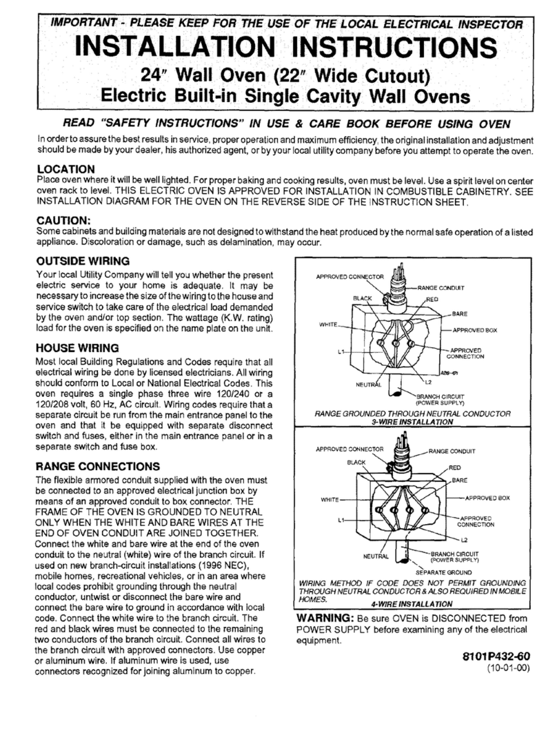
Sears 24 User manual