;
. l
table
of contents
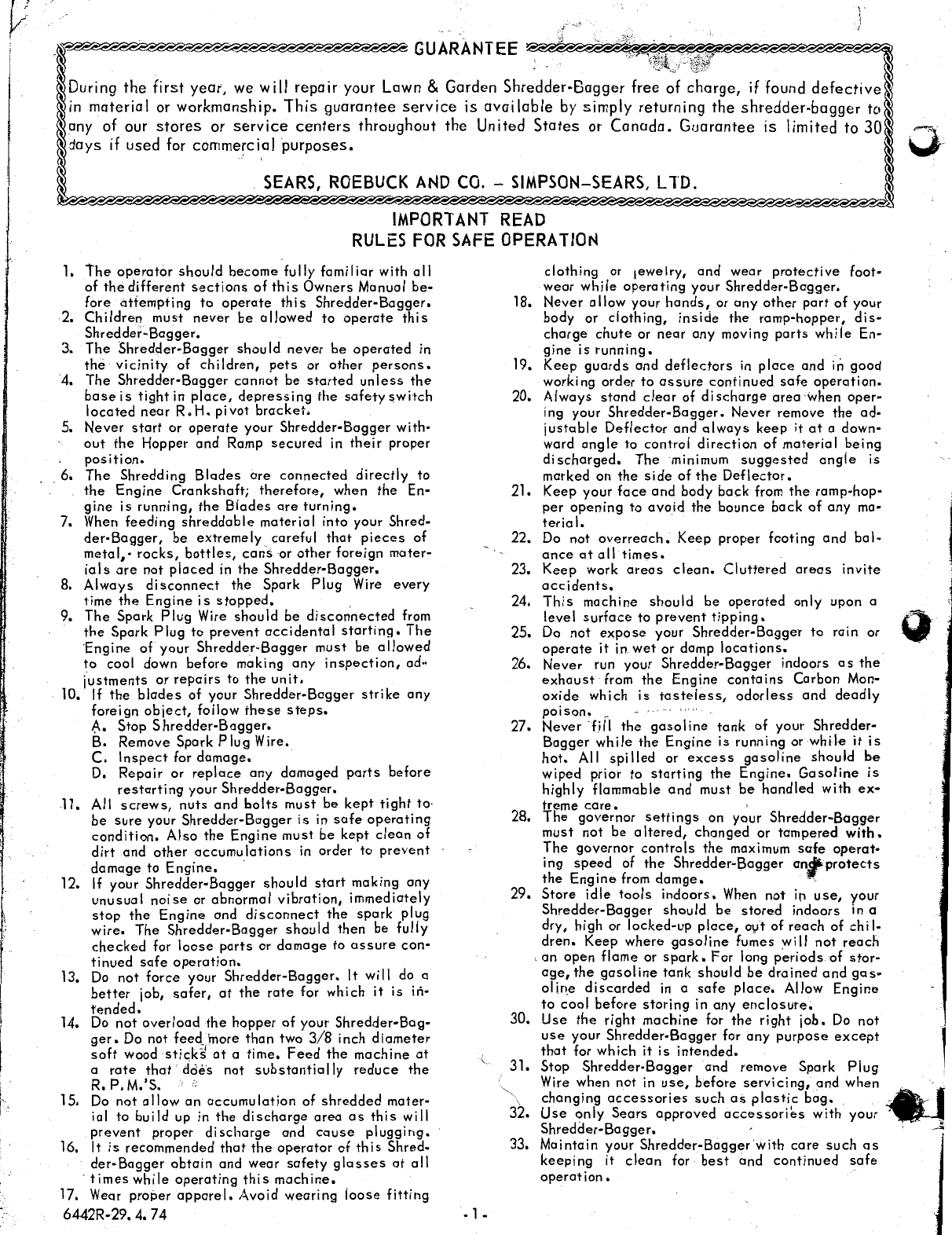
"GUARANTEE
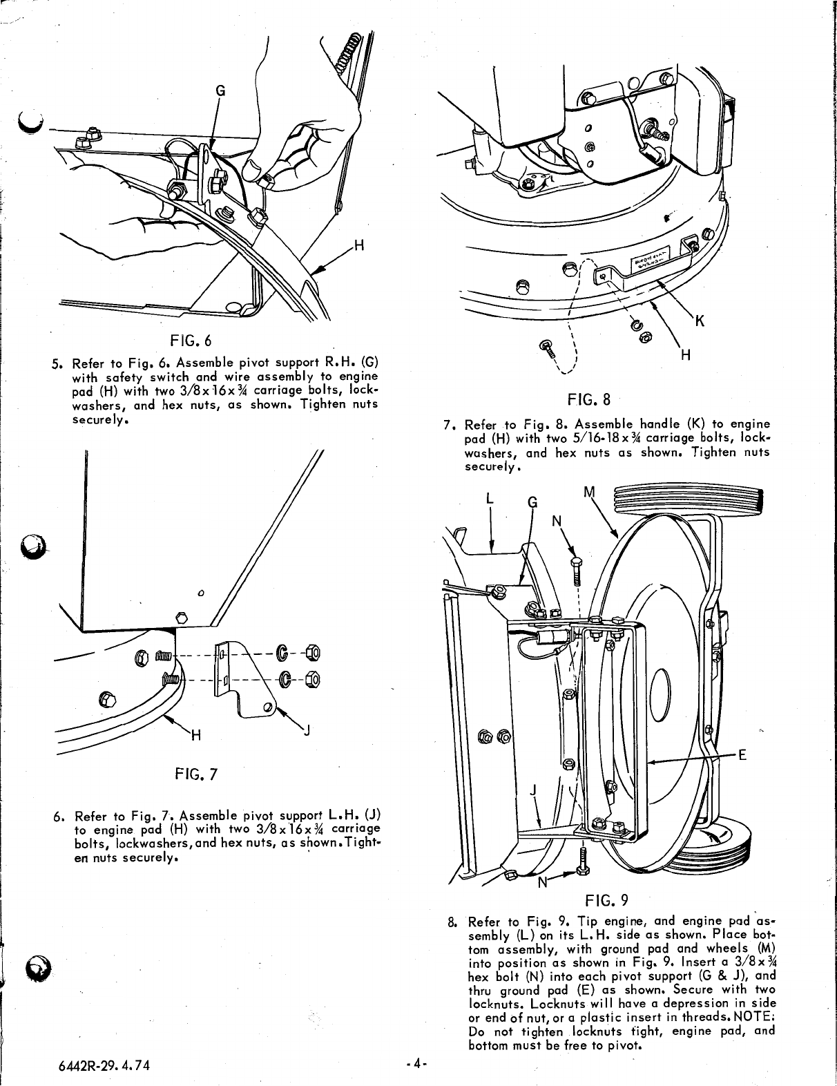
.#.
-RULES FOR SAFE OPERATION
ASSEMBLY INSTRUCTIONS
OPERATING
MAINTENANCE INSTRUCTIONS
REPAIR PARTS
3-7
7-10
10-13
15-23
tools required for assembly
of shredder-bagger
2 - 7
/16"
Wrenches
2 -
Yi"
Wrenches
2 -
9/16"
Wrenches
1 -
%"
Wrench
1 -
Pliers
1 -
Large
slotted
screwdriver
1 -
Large
phillips
screwdriver
assembly
A
letter
in
parenthesis
in
the
following
instructions
refers
to
an
arrow
in
an
adjoining
Figure
(Illustra-
tion),
unless
otherwise
stated.
When
R.H.
(Right
Hand) or
L.
H.
(Left Hand)
is
used,
it should be un·
derstood to mean
from
a
position
standing
at
the
han-
dles
and facing the Shredder-Bagger. Refer to
Fig.
1
Remove
all
parts
from
both inner
cartons.
All hard-
ware:
bolts,
nuts,
washers,
and
cotter
pins,
etc.
which
are
referred to
in
the
following
instruc~ions,
were
shipped
in a
plastic
bag.
Separate
all
bolts,
washers,
etc.,
according to
size.
Remove Shredder-
Bagger
from
carton.
Lay out
all
parts
for
assembly.
A
B
c
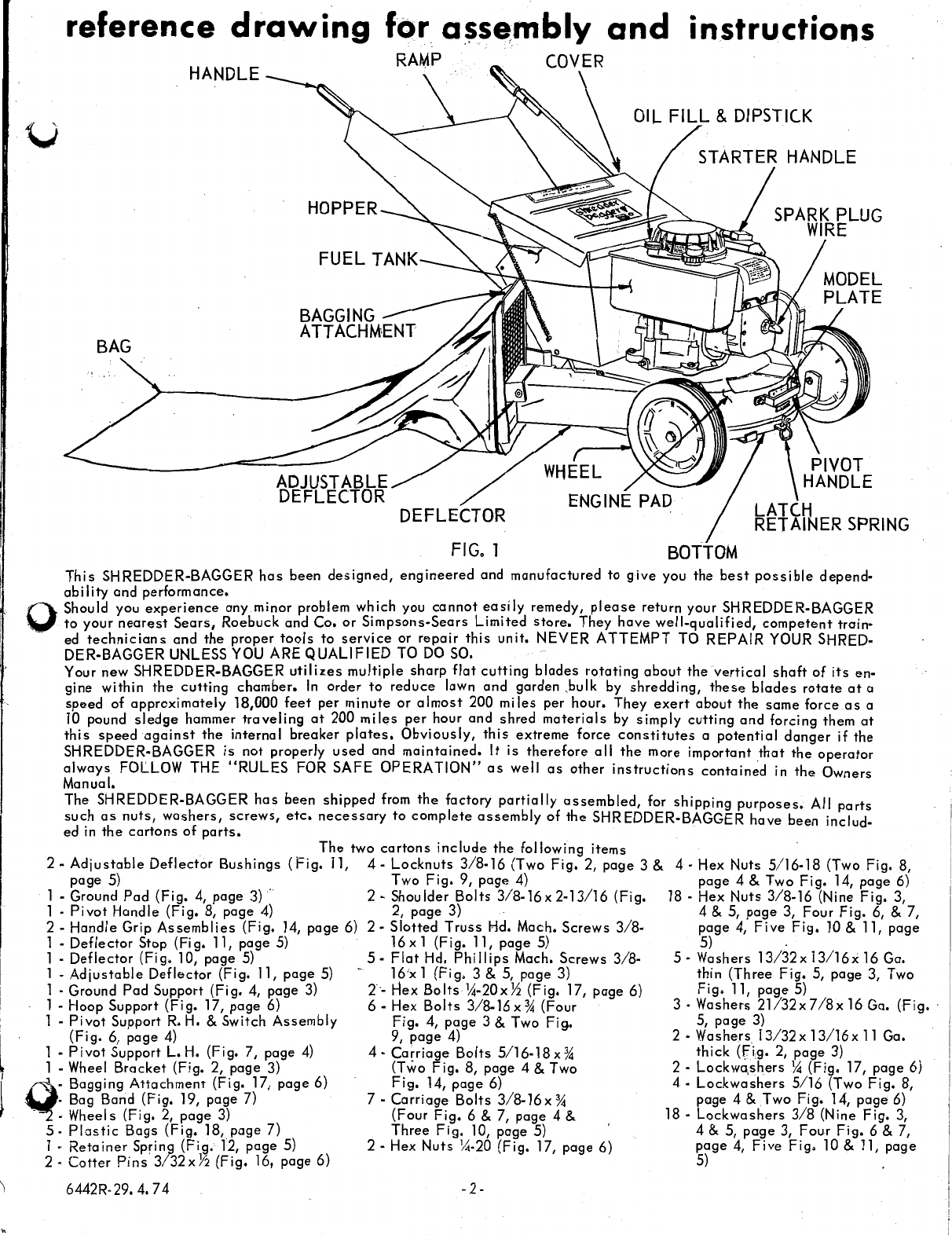
FIG. 3
2. Remove bottom from Shredder-Bagger. Refer
to
Fig.
3.
Assemble
wheel
bracket
(B) with
wheels
to
bottom·
(D)
as
shown.
Use
two
3/8-16x
1
flat
hd.
phillips
mach.
screws,
lockw'ashers, and hex
nuts.
Screws,
lockwashers,
and hex
nuts
were
in
plastic
bag.
Tighten
nuts
securely.
--------
E
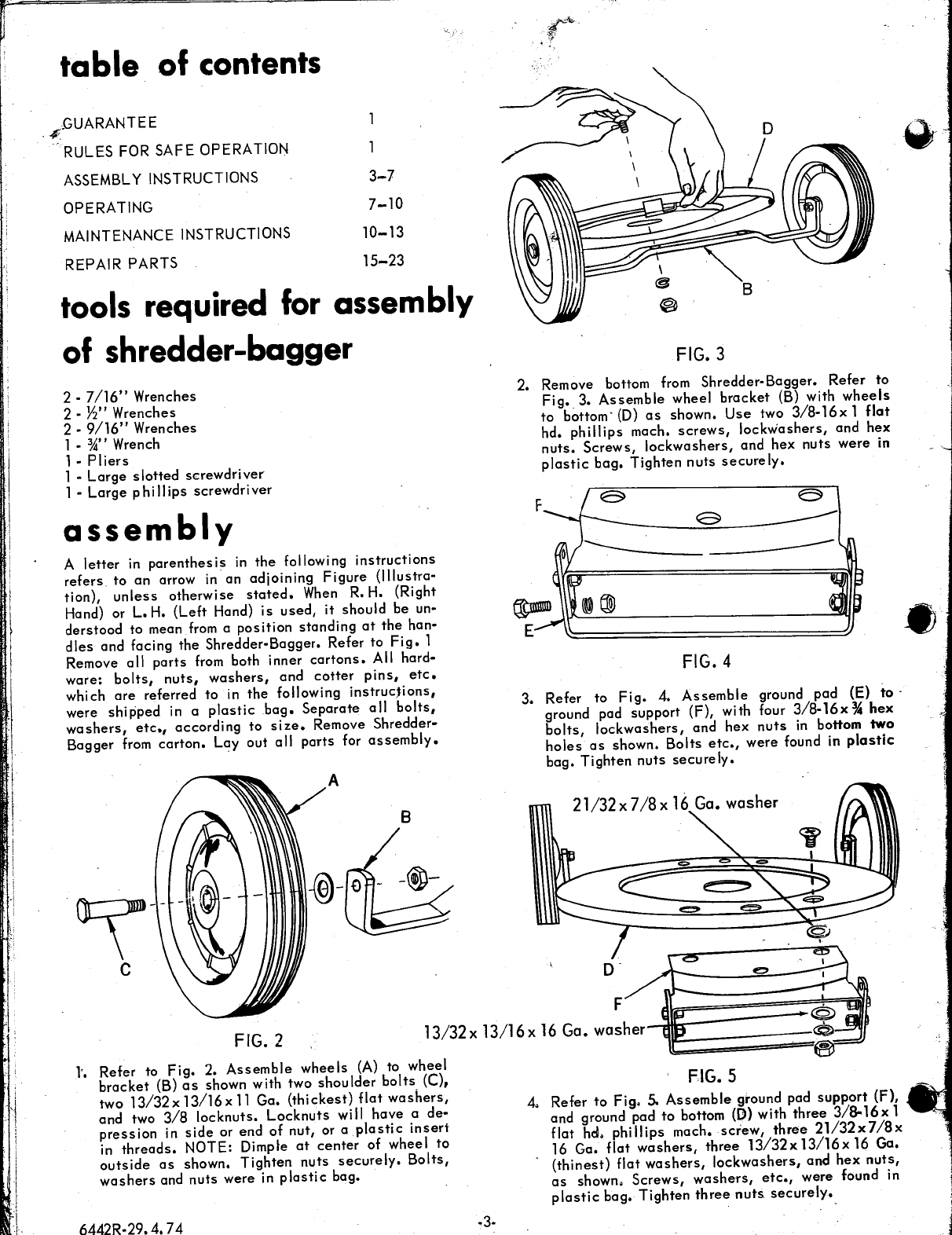
FIG. 4
3. Refer to
Fig.
4.
Assemble
ground pad (E)
to·
ground pad support (F), with four
3/8-16x
%
hex
bolts,
lockwashers
and
hex
nuts
in
bottom two
holes
as
shown.
B~lts
etc.,
were found in
plastic
bag. Tighten
nuts
securely.
FIG. 2
F
l3/32x
13/16x
16
Ga. washer
l'. Refer to
Fig.
2.
Assemble
wheels
(A)
to wheel
bracket
(B)
as
shown with two
shoulder
bolts_ (C),
two
13/32x
13/16x
11
Ga.
(thickest)
flat
washers,
and two
3/8
lockouts,
Lockouts
will
have
a
de·
pression
in
side
or end of nut, or a
plastic
insert
in
threads.
NOTE: Dimple
at
center
of wheel
to
outside
as
shown. Tighten
nuts
securely.
Bolts,
washers
and
nuts
were in
plastic
bag. .
6442R-29.4. 74
FIG. 5
4. Refer to
Fig.
S.
Assemble
ground pad
support
(F),
and ground pad to bottom
(D)
with
three
3/8-16x
1
flat hd.
phillips
mach.
screw,
three
21/32x7/8x
16 Ga.
flat
washers,
three
13/32x
13/16x
16 Ga.
(thinest)
flat
washers,
lockwashers,
and
hex
nuts,
as
shown.
Screws,
washers,
etc.,
were found in
p
las
tic
bag. Tighten
three
nuts
securely._
~-·
•