logo
Brands
  1. Home
  2. •
  3. Brands
  4. •
  5. Sears
  6. •
  7. Sander
  8. •
  9. Sears Craftsman 319.226560 User manual

Sears Craftsman 319.226560 User manual

This manual suits for next models

1

Other Sears Sander manuals

Sears CRAFTSMAN 9.25961 User manual

Sears

Sears CRAFTSMAN 9.25961 User manual

Sears Craftsman 113.225900 User manual

Sears

Sears Craftsman 113.225900 User manual

Sears CRAFTSMAN 315.11690 User manual

Sears

Sears CRAFTSMAN 315.11690 User manual

Sears 103.22350 Use and care manual

Sears

Sears 103.22350 Use and care manual

Sears Craftsman 315.116070 User manual

Sears

Sears Craftsman 315.116070 User manual

Popular Sander manuals by other brands

Oliver 6305 owner's manual

Oliver

Oliver 6305 owner's manual

Jet 22-44 Pro-3 Operating instructions and parts manual

Jet

Jet 22-44 Pro-3 Operating instructions and parts manual

Makita M9204 technical information

Makita

Makita M9204 technical information

Makita M9204 instruction manual

Makita

Makita M9204 instruction manual

Clarke Woodworker CBS1-5B Operation & maintenance instructions

Clarke

Clarke Woodworker CBS1-5B Operation & maintenance instructions

Chicago Pneumatic CP9778 Operator's manual

Chicago Pneumatic

Chicago Pneumatic CP9778 Operator's manual

Nitto Kohki BB-20 instruction manual

Nitto Kohki

Nitto Kohki BB-20 instruction manual

Ferm FEOS-135 user manual

Ferm

Ferm FEOS-135 user manual

Unior 1510 Operating	 instruction

Unior

Unior 1510 Operating instruction

stayer ls1200 operating instructions

stayer

stayer ls1200 operating instructions

Jet JSG-96 Operating instructions and parts manual

Jet

Jet JSG-96 Operating instructions and parts manual

Parkside PDS 290 B2 Operation and safety notes

Parkside

Parkside PDS 290 B2 Operation and safety notes

Status XPA Series Original instructions

Status

Status XPA Series Original instructions

Clarke EZ Sand Operator's manual

Clarke

Clarke EZ Sand Operator's manual

Craftsman 113.22521 owner's manual

Craftsman

Craftsman 113.22521 owner's manual

Craftsman 113.225831 owner's manual

Craftsman

Craftsman 113.225831 owner's manual

CLAS OP 1429 manual

CLAS

CLAS OP 1429 manual

Parkside PEXS 270 Al user guide

Parkside

Parkside PEXS 270 Al user guide

https://manuals.online logo
https://manuals.online logoBrands
  • About & Mission
  • Contact us
  • Privacy Policy
  • Terms and Conditions

Copyright 2025 Manuals.Online. All Rights Reserved.

®
Save This Manual For Future Reference
OW °
MANUAL
Model No.
319.226560
Serial No.
Model and serial
numbers may be
found on the nam
plate located on the
front of the tool. You
should record both
the model and serial
number and retain it
in a safe place for
future use.
Caution:
Read, understand and
follow ALL Instruc-
tions and rules for
safe operation before
operating this tool.
LT/
SANDER C
•Warranty
.Safety Instructions
"KnowYour Belt/Disc Sander
•Operation and Maintenance
• Repair Parts
226560102
226560102
Sears, Roebuck and Co., Hoffman Estates, lL 60179 U.S.A.
NRTL/C
LR 78936
FULL ONE-YEAR WARRANTY ON SEARS BELT and DISC SANDER
If this Sears Craftsman Belt and Disc Sander fails due to a defect in material or workmanship
within one year' from the date of purchase, RETURN ITTO THE NEAREST SEARS SERVICE
CENTER INTHE UNITED STATES, and Sears will repair it, free of charge.
If this Belt /Disc Sander is used for cormnercial or rental purposes, this warranty will apply
for ninety days from the date of purchase.
This warranty applies only while this product is in the United States.
This warranty gives you specific legal rights and you may also have other rights which vary
from state to state,
Sears, Roebuck and Co,, Dept. 817 WA, Hoffman Estates, IL 601 79
SAFETY INSTRUCTIONS FOR BELT/DISC SANDER
mBEFORE USING THE BELT/DISC SANDER:
1. READ and become familiar with this 6.
entire instruction manual. LEARN the
tools applications, limitations, and possible
hazards,
2_ AVOID DANGEROUS CONDITIONS.
DO NOT use power tools in wet or damp
areas or expose them to rain.
DO NOT use power tools in the presence
of flammable liquids or gases.
4. ALWAYS keep your woik area clean,
uncluttered and weU lit. DO NOT work on
floor surfaces that are slippery from
,sawdust or wax.
KEEP VISITORS AND CHILDREN
AWAY, Other people should keep a safe
distance from the work area, especially
when tool is operating
,
,
DO NOT FORCE THE TOOL. Never
force a tool to do a job for which it was not
designed It will do a better and safer job by
only using on jobs for which it was
designed.
DRESS FOR SAFETY. DO NOT wear
loose clothing, gloves, neckties, or jewelry
(rings, watches); they can get caught and
draw you into moving parts. ALWAYS
wear non-slip footwear; tie back long hair.
WEAR A FACE HASK OR DUST
HASK IF SANDING OPERATION
PRODUCES DUST.
ALWAYS remove the power cord plug
from the electric outlet when making
adjustments, changing pat,s, cleaning or
working on tool.
10. KEEP GUARDS IN PLACE AND IN
WORKING ORDER.
SAVE THESE INSTRUCTIONS
Page 2
SAFETY INSTRUCTmONS CONTINUED
11 ALWAYS WEAR EYE PROTECTION. Any Sander can throw foreign objects into the
eyes which could cause permanent eye damage ALWAYS Wear Safety
WEARYOUR Goggles (not glasses) that comply with ANSI safety standard Z87o t,
Everyday eyeglasses have only impact-resistant lenses._ they ARE NOT
safety glasses Safety Goggles are available at Sears,
NOTE: Glasses or goggles not in compliance with ANSI Z87,1 coiald
seriously hurt you when they break,
12_ AVOID ACCIDENTAL STARTING.
Ensure that the power switch is in the
"OFF" position before plugging in the
power cord
13, REMOVE ADJUSTING TOOLS. Form
habit of checking to see that tools and
adjusting wrenches are removed from the
sander before turning it on_
14_ USE ONLY RECOMMENDED
ACCESSORIES. Using improper
accessories can be hazardous. If in doubt,
check the instruction manual that comes
with that accessory,
t9, CHECK DAMAGED PARTS. Before
each use of tool, a guard or other part that
is damaged should be carefully checked to
determine that it will operate properly and
perform its intended function. Check for
alignment of moving parts, binding of
moving parts, breakage of parts, mounting
or any other conditions that may affect its
operation, A guard or other part that is
damaged should be properly repaired or
replaced°
20_ MAKE WORKSHOP CHILDPROOF.
By use of padlocks, master switches, or by
removing starter keys_
15, NEVER LEAVE A TOOL RUNNING
UNATTENDED. Turn the power switch
to "OFF", DO NOT leave too! until it has
come to complete stop
16. NEVER STAND ON A TOOL. Serious
injury could result ff the tool tips or you
accidentally hit the sander, DO NOT
store anything above or near the toot
where anyone might stand on the tool to
reach it
17. DON'T OVERREACH. Keep proper
footing and balance at all times. Wear
oil-resistant r_ubber_soted footwear. Keep
floor clear of oil, scrap and other debris
18. MAINTAIN TOOLS WITH CARE.
Always keep tools clean and in good
working order
21,
22
23
24
DRUGS, ALGOHOL OR
MEDICATIONS. DO NOT operate tool if
you are under the i_n£1uence of drugs,
alcohol or medication that could affect
3,our ability to use the tool properly,
SECURE ALL WORK. When practical,
use clamps or a vise to hold work, It is sager
than using your hands and prevents round
or odd-shaped pieces from turning.
,DIRECTION OF FEED. Feed work into a
blade or cutter against the direction of
rotation of the blade or cutter ordyo
WARNING: Dust generated from certain
materials can be injuriou s to your health.
Always operate sander in well ventilated
areas and provide for proper dust removal
SAVE THESE INSTRUCTIONS
Page 3
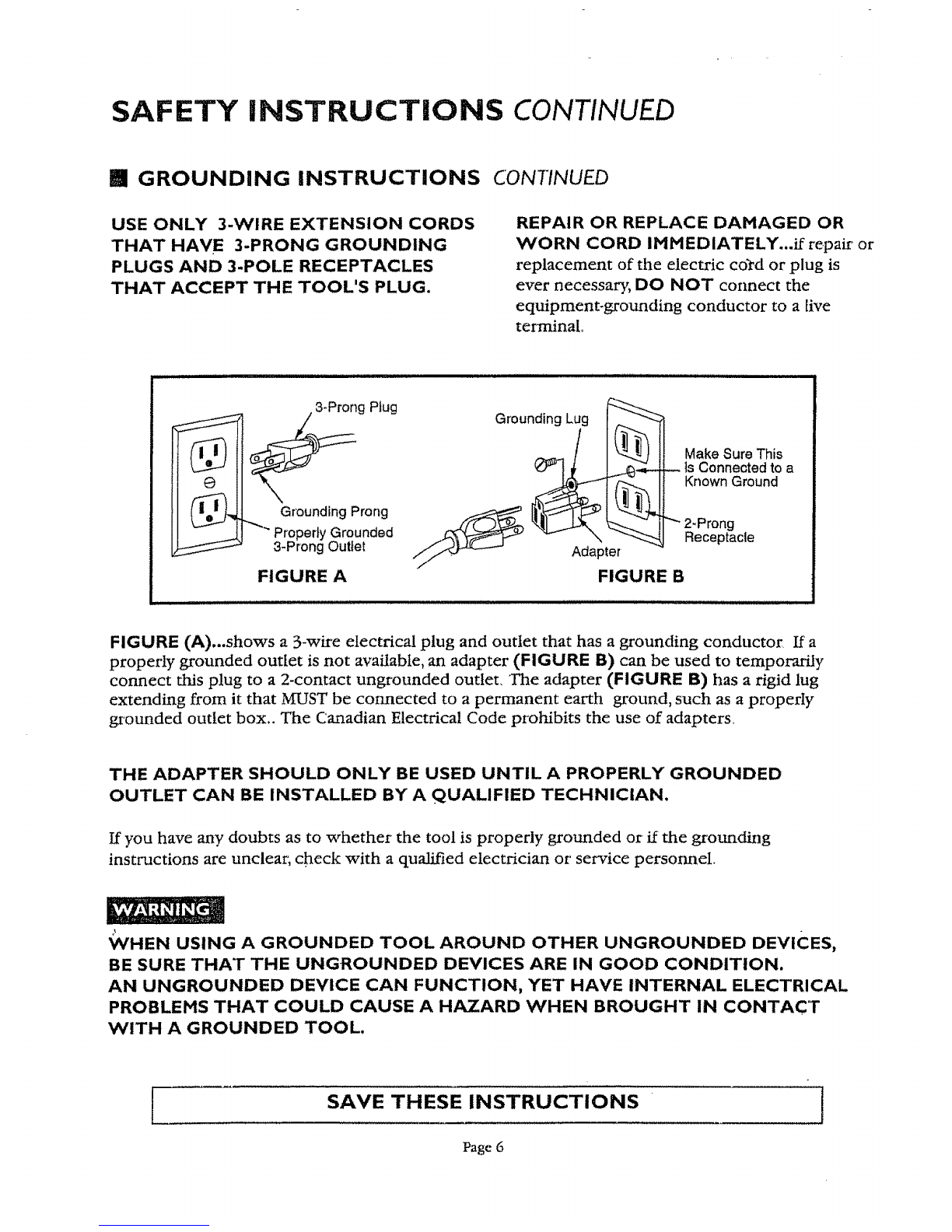
SAFETY INSTRUCTIONS CONT/NUED
[] ADDITIONAL SA!FETY INSTRUCTIONS FOR BELT/DISC SANDER
DO NOT OPERATE YOUR SANDER UNTIL IT IS COMPLETELY ASSEMBLED AND
INSTALLED ACCORDING TO THE INSTRUCTIONS.
I .THIS SANDER IS DESIGNED TO SAND
WOOD OR WOOD-LIKE PRODUCTS
ONLY. Sanding or grinding other materials
could result in fire, injury or- damage to
workpiece_
2 MOUNT AND USE this sander on
hoxizontal surfaces only. Operating sander
when mounted on non-horizontal surfaces
might result in motor damage_
3IF THERE IS ANY TENDENCY for the
machine to tip over or move during any
use, the sander must be securely fastened
to the bench top or supporting surface,
4. MAKE SURE the sanding belt is instaUed
in the correct direction See directional
arrow on back of belt,
5. ALWAYS have the tracking adjusted
properly so the belt does not run off the
pulleys
6 DO NOT USE sanding belts or discs that
are damaged, torn, loose, Use only correct
size sanding belt mid disc
7 ALWAYS HOLD the workpiece firmly
when sandingAvoid awkward hand
positions when a slip could cause a hand
to move into the sanding belt or disc.
Sand only one workpiece at a time.
8, ALVVAYS HOLD the workpiece firmly on
the table when disc sanding and when
using either table when belt sanding,
9, ALWAYS SAND ON THE
DOWNWARD SIDE of the sanding disc
when using the disc sander Sanding on the
upward side of the disc could cause the
workpiece to fly up which could be
hazardous,
10 ALWAYS maintain a minimum clearance
of 1/16 inch or less between tile table or
backstop and the sanding belt or disc
1 1, DO NOT sand pieces of material that are
too small to be safely supported
12. WHEN sanding a large workpiece, provide
additional support at table height.
13. DO NOT sand with the workpiece
unsupported. Support the workpiece with
the backstop or tableiFhe only exception
is curved work performed on the outer
sanding drum.
14. ALWAYS remove scrap pieces and other
objects from the table, backstop or belt
before turning the sander "ON?'
15 N EVE R perform layout, assembly or set-up
work on the table while the sander is
operating,
16 NEVER use solvents to clean plastic parts,
Solvents could possibly dissolve or other
wise damage the material, Only a soft damp
cloth should be used to clean plastic parts,
17. SHOULD any part of your sander be
missing, damaged, or fail in any way, or
any electrical components fail to perform
properly, shut off switch and iemove plug
f_'om power supply outlet. Replace
missing, damaged Or failed parts before
resuming operation
18 NEVER YANK THE POWER CORD
out of the receptacle. Keep cords away
from heat, oil and sharp edges.
19 HAVE AN ELECTRICIAN REPLACE
OR REPAIR damaged or worn cords
immediately,
iSAVE THESE INSTRUCTIONS ]
Page 4
SAFETY INSTRUCTHO.NS CONTINUED
l_ ADDITIONAL SAFETY RNSTRUCTIONS FOR BELT/DISC SANDER
20USE PROPER EXTENSION CORD. Make sure your extension cord is in good condition
When using an extension cord, be sure to use one heavy enough to carry the current your
product will draw_ An undersized cord will c;mse a drop in line voltage resulting in loss of
power and overheating° The table below shows the correct size to use depending on cord
length and nameplate ampere rating If in doubt, use the next heavier gauger The smaller the
gauge number, the heavier the cord
mGUIDELINES FOR USING EXTENSION CORDS
tTJll_lltTJlil|Tt|i___ii t_'];;ll_;[o ;l_:_llt¢l_l--"][t]i'l|l'IO]_}i},: ivT
,(when using 120 volts only)
Ampere Rating Total length of cord in feet
more than not more than 25' 50' 100' '150'
=_1 ,, .....
0 6 18 16 16 14
6 10 18 16 14 12
t0 12 16 16 14 12
12 16 14 12 Not Recommended
if you are using an extension cord outdoors, be sure it is marked with the suffix "W-A"
("W" in Canada) to indicate that it is acceptable for outdoor use
Be sure your extension cord is properly wired, and in good electrical condition Mways
replace a damaged extension cord or have it repaired by a qualified person before using it,
Protect your extension cords from sharp objects, excessive heat and damp or wet areas,
iGROUNDING INSTRUCTIONS
IN 'THE EVENT OF A blALFUNCTION OR BREAKDOWN, grounding provides a
Columns path of least resistance for electric current to reduce the risk of electric shockThis tool
is equipped with an electric cord having an equipment-grounding conductor and a
grounding plugThe plug MUST be plugged into a matching outlet that is properly installed and
grounded in accordance with' A_LL local codes and ordinances
DO NOT MODIFY THE 3-PRONG PLUG...if it will not fit the outlet, have the proper outlet
installed by a qualified electrician, Improper connection of the equipment-grounding conductor
can result in a risk of shock,The conductor with insulation having an outer surface that is green
(sometimes,but not always with yellow stripes) is the equipment grounding conductor
SAVE THESE INSTRUCTIONS
Page 5
I
SAFETY INSTRUCTIONS CONTINUED
mGROUNDING INSTRUCTIONS CONTINUED
USE ONLY 3-WIRE EXTENSION CORDS
THAT HAVE 3-PRONG GROUNDING
PLUGS AND 3-POLE RECEPTACLES
THAT ACCEPT THE TOOL'S PLUG.
REPAIR OR REPLACE DAMAGED OR
VVORN CORD IMMEDIATELY...if repair or
replacement of the electric cord or plug is
ever necessary, DO NOT connect the
equipment-grounding conductor to a live
terminal.
ii it i ,,,
_ s3_ProngPtug
Grounding Prong
"Properly Grounded
3-Prong Outlet
FIGURE A
tllllll
Grounding Lug
FIGURE B
Make Sure This
Is Connected to a
Known Ground
"_ 2-Prong
Receptacle
FIGURE (A)...shows a 3-wire electrical plug and outlet that has agrounding conductor If a
properly grounded outlet is not available, an adapter (FIGURE B) can be used to temporarily
connect this plug to a 2-contact ungrounded outlet, The adapter (FIGURE B) has a rigid lug
extending from it that MUST be com, lected to a permanent earth ground, such as a properly
grounded outlet box., The Canadian Electrical Code prohibits the use of adapters,
THE ADAPTER SHOULD ONLY BE USED UNTIL A PROPERLY GROUNDED
OUTLET CAN BE INSTALLED BY A QUALIFIED TECHNICIAN.
If you have any doubts as to whether the tool is properly grounded or' if the grounding
instructions are unclear; check with a qualified electrician or service personnel
_/HEN USING A GROUNDED TOOL AROUND OTHER UNGROUNDED DEVICES,
BE SURE THAT THE UNGROUNDED DEVICES ARE IN GOOD CONDITION.
AN UNGROUNDED DEVICE CAN FUNCTION, YET HAVE INTERNAL ELECTRICAL
PROBLEMS THAT COULD CAUSE A HAZARD WHEN BROUGHT IN CONTACT
WITH A GROUNDED TOOL.
[SAVE THESE INSTRUCTIONS
Page 6
J
TABLE OF CONTENTS
SECTION PAGE
Warranty............................................................... 2
Safety Instructions ............................................... 2
Extension Cord Use ............................................. 5
Specifications ....................................................... 7
UnpacMng and Checking Contents ..................... 8
Know Your Belt/Disc Sander ................................ 9
Assembly. ............................................................ 10
Fastening Sander to Work Surface ....................... 11
Operation and Adjustment .................................. 12
Maintenance ....................................................... 15
Parts List............................................................. 16
BELT/DiSC SANDER SPECIFICATIONS
Belt Size:
Disc Diameter:
Motor:
Speed (R.P.M.):
Net Weight:
Dimensions:
Belt Bed Tilt:
Disc Table Size:
Disc Table Tilt:
Bed Table Size:
Belt Table Tilt:
4 in, x 36 in.
8 in.
120VAC, 60 Hz, 6oOA
3450 R EM (no load)
approx. 43 LB
approxo 17 t/2 in. x 7 t/2 in. x 11 in.
0o . 90 °
10 i/2 in_x 6 1/4in,
0 ° to450
6Lq.x 4 in.
45" -90'
Page
UNPACKING AND CHECKING CONTENTS
_[ Tools needed for assembly and alignment: (see figure t)
1, Combination Square
2_Two hex keys (supplied)
3. Slotted and phillips screwdriver
4_Adjustable wrench
Bi Unpacking (see figure 2) Fig. I
This belt disc/sander is shipped complete in one carton Carefiflly unpack the sander and all parts
from the carton.
If any parts are missing, do not attempt to operate the sander until the missing parts are obtained
and correctly installed.
Separate all parts from carton and check for each item as listed:
PARTS LIST
1) Belt and disc sander
6
4
Hex head bolt (3 each)
Hex cap screw (3 each) 10
Fig. 2
Note: Do not discard packaging until aU parts have been assembled.
FOR YOUR OVeN SAFETY, DO NOT CONNECT THE SANDER'S PLUG INTO A
POWER OUTLET OR INSERT THE SWITCH KEY UNTIL THE PARTS ARE
CORRECTLY INSTALLED AND ADJUSTMENTS HAVE BEEN MADE.
Page 8
KNOW YOUR BELT/DmSC SANDER
Dust deflector
BACKSTOP --
Sanding plate
Sanding disc
DISC TABLE
BELT TABLE
-- Sanding belt
---- Belt bed
Fig. 3
" Idler drum
--- Disc guard
ON/OFF switch
with key
Base mounting
hole
KEY GUIDES FOR PROFESSIONAL RESULTS
DISC TABLE: is used to support workpiece when using sanding disc or when using belt
sander in vertical position.
BELT TABLE: is used to support workpiece when edge sanding on the belt only,
BACKSTOP: holds the workpiece when using sander in horizontal position, Can be removed
when sanding operation requires use of the entire belt.
Tension lever
Tracking knob
Holding bracket
Belt table
adjust knob
Drive belt
Drive belt
adjusting hole
2 Hex keys
(5 & 6mm)
Fig. 4
Adjusting bracket
Tilt lock
Backstop locking
screw
Bed locking screw
Drive belt housing
Spring load handle
Dust chute
Power cord
Drive belt
housing cover
TO AVOID INJURY FROM ACCIDENTAL STARTING, TURN SWITCH "OFF" AND REMOVE
PLUG FROM POVVER SOURCE OUTLET BEFORE MAKING ANY ADJUSTMENTS.
:: .:: ..... Page 9 _: .,
ASSEMBLY
Ill Installing the sanding disc (see figure 5)
1, Remove the two screws from the sanding disc guard
and remove sanding disc guard plate.
2_Wipe sanding disc plate clean.
3, Peel backing from sanding disc, align disc with plate
and press saxlding disc firmly on to plate,
4, Reinstall disc guard and tighten screws_
[] Installing the sanding belt (see figure 6)
1 Loosen the bed locking screw, raise sanding bed 45", Fig. 5
tighten bed locking screw
2, Release the tension lever.
3. Locate the directional arrow on the smooth side of the
sanding belt,
4, Place the sanding belt over the drums with the directional
arrow pointing toward the dust chute,
5, Center belt correctly on both drams,,
6, Slide tension level to tighten belt to the bed_
7 Loosen bed locking screw, lower bed to horizontal position,
tighten bed locking screw
mi Mounting the disc sander table (see figures 7,8)
1.Align the bracket tO the bottom of the disc table.
2_ Insert a locking washer, followed by the flat
washer, on each screw,
3 Fasten bracket with screws to table.
4. Insert flat washer on disc table adjusting
knob.
5. install the table by lining up the indexing pin on
the table bracket with the pivot hole on the
frame.. Hold in place.
6 Insert the spring load handle into tile threaded
hole and tighten
7Loosen the three screws holding the table to the
bracket and adjust table so that edge is I/I6 inch
from the disc. Tighten screws,
Fig. 6
Fig. 7,8
TO AVOID TRAPPING THE WORK PIECE OR
FINGERS BETWEEN THE TABLE AND THE
SANDING DISC, THE TABLE EDGE SHOULD
BE ADJUSTED TO AMAXIMUM OF 1/L6 INCH
FROM THE SANDING DISC.
Page t0