Sears CRAFTSMAN 9.25961 User manual

‘4
$ears
owners
manual
MODEL
NO.
9.25961
CAUTION:
Read
ALL
GENERAL
and
SAFETY
INSTRUCTIONS
.‘arefuIIy
f
CRAFTSMAN
BELT
SANDER
STAND
assembly
operating
repair
parts
4
SOLD
BY
SEARS,
ROEBUCK
AND
CO.,
CHICAGO,
IL.
60684
U.S.A.
AND
SIMPSONS-SEARS
LIMITED,
TORONTO, ONTARIO,
CANADA.
Part
No.
90131
Printed
in
U.S.A.
6/76
‘4.
I
4

GENERAL
SAFETY
INSTRUCTIONS
FOR
BELT
SANDER
STAND
1.
ALWAYS
USE
EYE
PROTECTION.
The
operation
of
any belt
sander
can result
in
foreign
objects
being
thrown
into
the eyes,
which
can
resu
It
in
severe
eye
damage.
Always
wearsafety
glasses
or
eye
shields
before
operating
sander.
We
recommend
Wide
Vision
Safety
Mask
for
use
over
spectacles,
or
standard
safety
glasses
•
..
available
at
Sears
retail
or
catalog
stores.
2.
DON’T
FORCE
TOOL.
The
Belt
Sander
was
designed
for
smooth
operation,
therefore, parts
should
never
be
forced
into
the
belt
sander.
3.
KEEP
HANDS
CLEAR
OF
BELT
AND
WORKING
AREA.
4.
KEEP
BELT
SANDER
AND
STAND
CLEAN.
After
every
use,
clean
dust
off
Belt
Sander
and
Stand.
NOTE:
Motors
used
on
wood-working
tools are
particularly
susceptible
to
the
accumulation
of
dust
and
should
be
blown
out
or
“vacuumed”
frequently
to
prevent
interference
with
normal
motor
ventilation.
GENERAL
SAFETY
INSTRUCTIONS
FOR
POWER
TOOLS
1.
KNOW YOUR
POWER
TOOL
10.
USE
SAFETY
GOGGLES
Read
the
owner’s
manual carefully.
Learn
its
application
and
Safety
goggles
must
comply
with ANS
Z87.1
-1968. Also
use
limitations as
well
as
the
specific potential
hazards
peculiar face
or
dust
mask
if
cutting
operation
is
dusty.
to
this
tool.
11.
DON’T
OVERREACH
2.
GROUND ALL
TOOLS
Keep
proper
footing
and
balance
at
all
times.
The
sander
is
equipped
with
an
approved
3-conductor
cord
and
a
3-prong
grounding
type
plug
to
fit
the
proper
12.
MAINTAIN
TOOLS
WITH
CARE
grounding
type
receptacle.
The
green
conductor
in
the cord
Keep
tools
sharp
and
clean
for
best
and
safest performance.
is
the
grounding
wire.
Never
connect
the
green
wire
to
a
live
Follow
instructions
for
lubrication
and
changing
terminal.
accessories.
3.
KEEP
WORK
AREA
CLEAN
13.
DISCONNECT
TOOLS
Cluttered
areas
and
benches
invite
accidents.
Floor
must
Before
servicing;
when
changing
accessoriessuch
as
blades,
not
be
slippery due
to
wax
or
sawdust.
bits,
cutter,
belts, etc.
4.
AVOID
DANGEROUS
ENVIRONMENT
14.
AVOID
ACCIDENTAL STARTING
Don’t
use power
tools
in
damp
or wet
location.
Keep
work
Make
sure
switch
is
in
“OFF”
position before
plugging
in.
area
well
lit.
Provide
adequate
surrounding
work
space.
15.
USE
RECOMMENDED
ACCESSORIES
5.
KEEP
CHILDREN
AWAY Consult
the
owner’s
manual
for
recommended
accessories.
All
visitors
should
be
kept
a
safe
distance
from
work
area.
Follow
the
instructions
that accompany
the
accessories.
The
use
of
improper
accessories
may
cause
hazards.
6.
MAKE
WORKSHOP KID-PROOF
—with
padlocks,
master switches,
or
by
removing
starter
16.
CHECK
DAMAGED
PARTS
keys.
Before
further use
of
the
tool,
a
belt or
other
part
that
is
damaged
should
be
carefully
checked
to
ensure
that
it
will
7.
DON’T
FORCE
TOOL
operate
properly
and perform
its
intended
function. Check
It
will
do
the
job
better
and
safer
at
the
rate
for
which
it
was
for
alignment
of
moving
parts,
binding
of
moving
parts,
designed.
breakage
of
parts,
mounting,
and any
other conditions
that
may
affect
its
operation.
A
belt
or
other
part
that
is
damaged
8.
USE
RIGHT
TOOL
should
be
properly repaired
or
replaced.
Don’t
force
tool
r
attachment
to
do
a
job
it
was
not
designed
for.
17.
DIRECTION
OF
FEED
Feed
work
into
the
belt
at
direction
of
travel
of
the
belt.
9.
WEAR
PROPER
APPAREL
No
loose clothing,
gloves,
neckties
or jewelry
to
get
caught
in
moving
parts.
Rubber-soled footwear
is
recommended
for
best
footing.
Page
2
/

figure
1
ASSEMBLY
INSTRUCTIONS
FOR
BELT
SANDER
STAND
All
parts required
to
assemble
the
sander
stand
are
enclosed.
The
only
tools
required
are
a
screwdriver
and
pliers
or small
adjustable
wrench.
For
ease
of
assembly,follow
the
instructions
in
the
sequence
shown.
Refer
to
Figure
3
on
Page
4
for
proper
identification
of
parts.
We
suggest
reading
all
instructions
on
this
page
before
starting
to
assemble
the
stand.
Step
No.
I
—
Assemble
Front
Work
Table,
-
Figure
4,
Page
5.
First,
attach
2
to
8
as
shown using
six
screws,
lock
washers
and
square
nuts.
Next,
position
the
two
adjustable braces
over
the
screws,
then
assemble
one
plain
washer
and
one
wing
nut
to
each
screw.
Hand
tighten
wing
nuts
with
parts
in
position
shown
in
Figure
4.
Step
No.
2.
—
Assemble
Front
Sander
Support
to
Main
Base
-
Figure
5,
Page
5.
Two
front
sander supports
are
included.
3
for
the
3
inch
sander
and
3A
for
the
4
inch
sander.
The
main
base
I
has
two
sets
of
holes
for
attaching
the
front
support. Select
the
proper
support
for
your
sander.
Position
this
over
the matching
pair
of
holes
and
attach
securely
using
two
screws,
lock
washers
and
square
nuts.
Step
No.
3.—
Assemble
Rear
Sander
Support
to
Sander
Handle
-
Figure
1,
Page
3.
Assemble the rear
sander
support
4
to
yoursanderhandle
using
two
“U”
bolts,
plain
washers
and
wing
nuts.
Attach
the
lower”U”
bolt
first.
Next,
assemble
horizontal
support
6
over
ends
of
upper
“U”
bolt
before the
wing
nuts
and
washers
are
assembled.
Step
No.
4.
—
Assemble
Sander
with
Rear
Support
to
Main
Base
-
Figure
1,
Page
3,
and
Figure
5,
Page
5.
Position
the
sander
with
rear
support
on
the
main
base
I
so
that
the
sander
is
resting
on
the
front
support,
3
or
3A.
The
main
base
has
Next-
assemble
the rear
sander
support
brace
5to
4
and
I
using
two
screws,
lock
washers
and
square
nuts.
Figure
5
shows
this
in
the
position
for
the
Sears
3
inch
sander.
The
brace
is
assembled
in
a
similar
way
on
the
opposite
side
of
the rear
support
for
the Sears
4
inch
sander.
Step
No.
5
—
Final
Assembly
-
Figure
1,
Page
3.
The
work
table
may
now
be
assembled
to
the
main
base.
Position
the
slots
in
the
front
of
I
over the
two
screws
on
8
and
secure
with
two
plain
washers
and
wing
nuts.
The
sander
is
now
ready
for
mounting
on
a
work
table
using
the
mounting holes
provided.
t
USES
OF
THE
BELT
SANDER
STAND
Your
belt
sander
stand
is
designed
to
be
used
with
the
sander
in
a
vertical
position
as
shown
in
Figure
1,
or
with
the
sander
in
a
horizontal
position
as
shown
in
Figure
2.
When
in
a
vertical
position mitered
edges
may
be
sanded
by
adjusting
the
angle
of
the
work
table.
The
sander
may
be
changed
from
a
vertical
to
a
horizontal position
by
removing
the
two
wing
nuts, arrow
A
of
Figure
1,
and
rotating the
sander
to
the horizontal
position.
The
plastic
switch
locking
clip
is
supplied
for
holding
the
switch
of
the
Sears
4
inch
sander
in
position
for
continuous
operation.
This
switch
clip
is
not
needed
for
the
Sears
3
inch
sander.
1
two
sets
of
mounting holes
for
attaching
the rear
support.
The
set
of
holes
closest
to
the
hinge
joint
isfortheSears4
inch
sanderwhilethe
other
set
of
holes
is
for
the
Sears
3
inch
sander.
Assemble
the rear
support
using
two
screws,
lock
washers,
and
square
nuts.
Page
3

CRAFTSMAN
BELT
SANDER
STAND
—
MODEL
NO
9.25961
CONTENTS
OF
PACKAGE
Owners
Manual
Figure
3
Plastic
bag
containing
required
screws,
washers
nuts
and
two
U”
Bolts.
Page
4

SANDER
STAND
SUB-ASSEMBLIES
Figure
4
-
View
of
Front
Work
Table
3
figure
5
-
View
of
Sander
Stand
In
horizontal
position
Page
5

How
to
ORDER
Repair
Parts
S
€IfS
All
parts
listed
herein
may
be
obtained
from
any
SEARS, ROEBUCK
AND
CO.
or
SIMPSONS-SEARS
LIMITED
retail
or
catalog store.
If
____________________
the
parts
you
need are
not
stocked
locally,
your
order
will
be
electronically
transmitted
to
a
Sears
Repair Parts
Distribution
Center
for
expedited
handling.
owners
WHEN
ORDERING
REPAIR
PARTS,
ALWAYS
GIVE
THE
FOLLOWING INFORMATION
AS
SHOWN
IN
THIS
LIST.
manual
1.
The
PART
NUMBER
2.
The
PART
DESCRIPTION
3.
The
MODEL NUMBER
9.25961
4.
The
NAME
OF
ITEM
—
TABLE-BELT
SANDER
BELT
SANDER
STAND—MODEL
NO.
9-25961
MODEL
NO.
PARTS
LIST
9.25961
NO.
PART
NO.
DESCRIPTION
QUANTITY
1
90101-1
Main
Base
Assembly
1
2
90112-1
Work
Table
Assembly
1
3
90106
Front
Sander
Support
(3”
Sander)
1
3A
90107
Front
Sander
Support
(4”
Sander)
1
4
90108
Rear
Sander
Support
1
5
90109
Rear
Sander
Support
Brace
1
6
90110
Horizontal
Support
1
7
90130
Switch
Locking
Clip
1
8
90112
Work
Table
Base
1
S
ER
VICE
9
90131
Owner’s
Manual
1
isat
YOUR
Your
Sears merchandise
takes
on
added
value
when
you
discover
SERVICE
that
Sears
has
over
2,000
Service
Units
throughout
the
country.
Each
is
staffed
by
Sears-trained,
professional
technicians
using
wherever
YOU
Sears approved
parts
and
methods.
live
or
move
in
the
U.S.A.
SOLD
BY
SEARS,
ROEBUCK
AND
CO.,
CHICAGO,
IL.
60684
U.S.A.
AND
SIMPSON-SEARS
LIMITED,
TORONTO, ONTARIO,
CANADA.
Part
No.
90131
Printed
in
U.S.A.
6/76
Table of contents
Other Sears Sander manuals
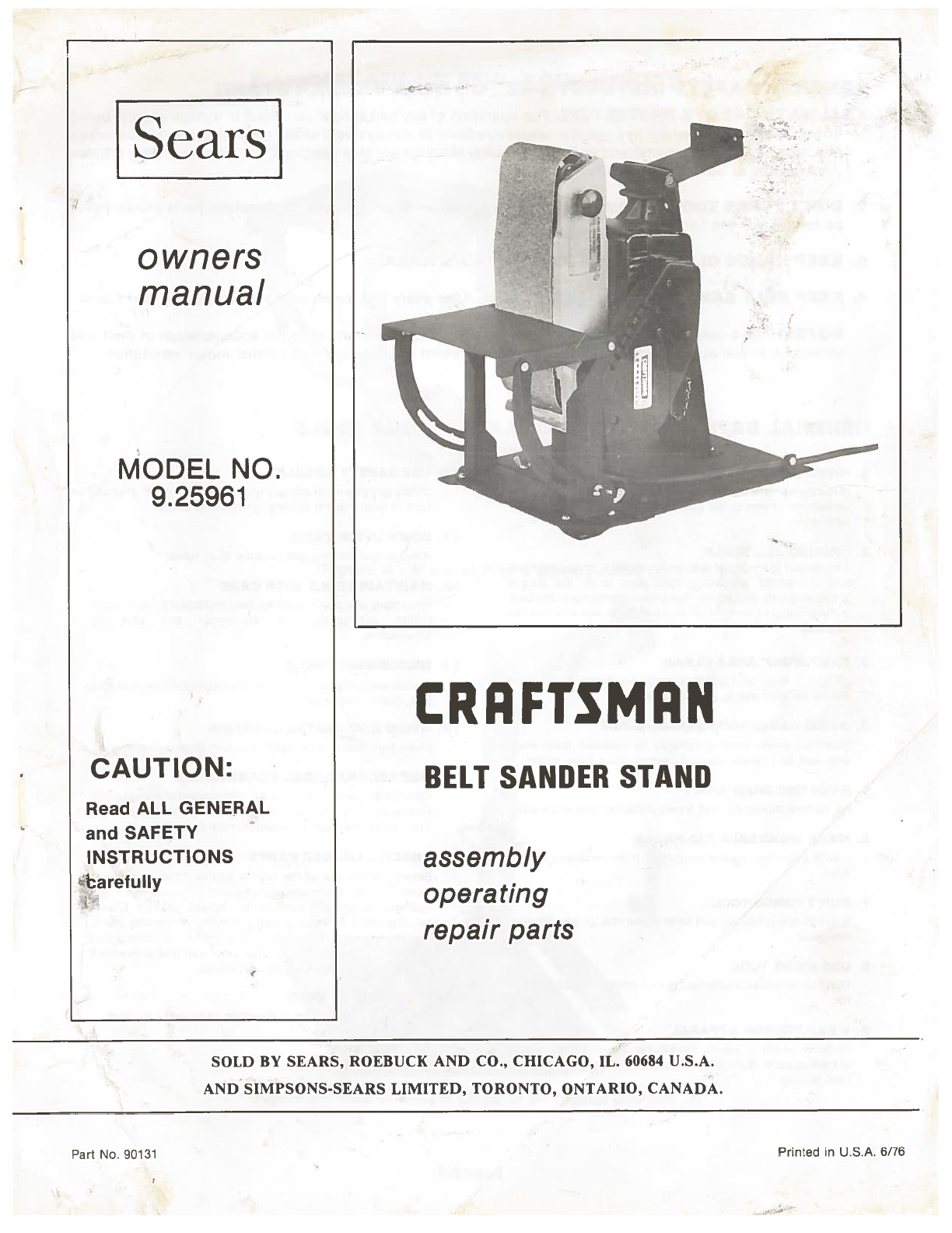