Seaside 9357 User manual

1
GARAGE DOOR OPENER
Models 9357·9367
For Residential Use Only
Owner’s Manual
Please read this manual and the enclosed safety materials carefully!
Fasten the manual near the garage door after installation.
The door WILL NOT CLOSE unless The safety is connected and properly aligned.
Periodic checks of the opener are required to ensure safe operation.
The model number label is located on the left side panel of your opener
www.seaside.net.cn DALIAN SEASIDE DOOR CONTROLLING SYSTEM CO.,
LTD.
TABLE OF CONTENTS
Introduction 2-6
Assembly 7-9
Installation 10-18
InstallTheWallControl 19-20
Install The Photo Eye Safety System 21-22
Power 23-24
Adjustments 24-28
Operation 29
WallControl 30
RemoteControl 30
To Erase the Memory 30
ToOpentheDoorManually 31
Maintenance 31
RepairParts 32-33
Troubleshooting 34

2
WARNING
WARNING WARNING
WARNING
INTRODUCTION
Safety Symbol and Signal Word Review
This garage door opener has been designed and tested to offer safe service provided it is installed, operated,
maintained and tested in strict accordance with the instructions and warnings contained in this manual.
When you see these Safety Symbols and Signal Words on the following pages, they will alert you to
the possibility of serious injury or death if you do not comply with the warnings that accompany them.
The hazard may come from something or from electric shock. Read the warnings carefully.
Mechanical Electrical
When you see this Signal Word on the following pages, it will alert you to the possibility of damage to
your garage door and/or the garage door opener if you do not comply with the cautionary statements
that accompany it. Read them carefully.
Check your garage door
1 Disable locks and remove any ropes connected to the garage door.
2 Lift the door halfway up. Release the door. If balanced, it should stay in place, supported entirely by its springs.
3 Raise and lower the door to check for binding or sticking. If your door binds, sticks, or is out of balance, call a trained door
systems technician.
4 Check the seal on the bottom of the door. Any gap between the floor and the bottom of the door must not exceed 1/4 inch
(6 mm). Otherwise, the safety reversal system may not work properly.
5 The opener should be installed above the center of the door. If there is a torsion spring or center bearing plate in the way of
the header bracket, it may be installed within 4 feet (1.2 m) to the left or right of the door center. See Installing the Header
Bracket section.
CAUTION
To prevent possible SERIOUS INJURY or DEATH:
ALWAYS call a trained door systems technician if
garage door binds, sticks, or is out of balance. An
unbalanced garage door may not reverse when
required.
NEVER try to loosen, move or adjust garage door,
door springs, cables, pulleys, brackets or their
hardware, ALL of which are under EXTREME
tension.
Disable ALL locks and remove ALL ropes
connected to
d BEFORE i t lli d ti
CAUTION
To prevent damage to garage door and opener:
ALWAYS disable locks BEFORE installing and
operating the opener.
ONLY operate garage door opener at 120V, 60 Hz to
avoid malfunction and damage.
To reduce the risk of injury to persons
Use this operator only with Sectional Door.
3
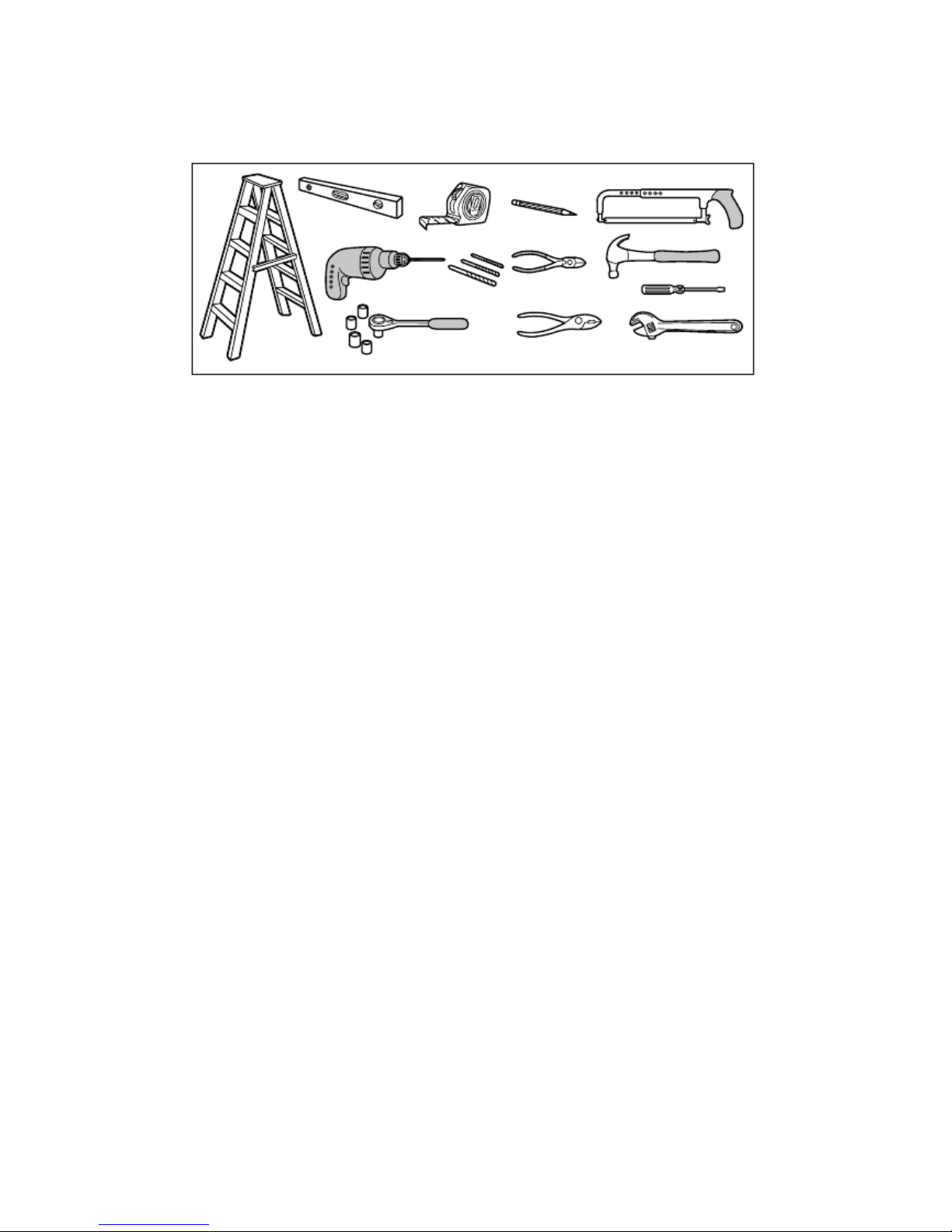
Tools needed
During assembly, installation and adjustment of the opener, instructions will call for hand tools as illustrated below.

4
Overview/Carton Inventory
GARAGE DOOR OPENER ASSEMBLY
Overview/Carton Inventory
A B
C
D
E
F
G
H
I
J
K
L
M
N
P
O
Q
A. Header bracket
B. Pulley assembly
C. Door bracket
D. Curved door arm
E. Straight door arm
F. Trolley assembly
G. Emergency release rope and handle
H. Rail
I. Rail Connectors(2)
J. Hanging brackets(2)
K. Garage door opener
L. “U” rail clips(3)
M. Safety reversing sensors
N. Chain
O. Sprocket and sprocket holder assembly
P. Wall Control Panel
Q. Safety labels and literature
5
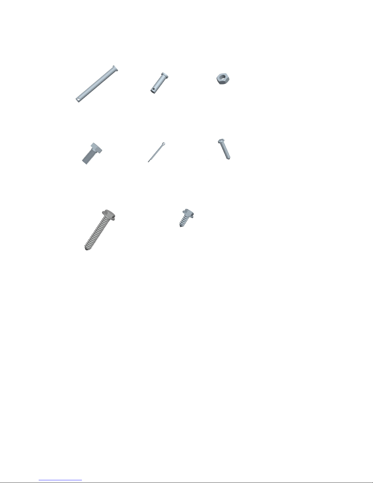
ASSEMBLY HARDWARE
Overview/Carton Inventory
H1 Clevis Pin, long
Φ8×80 (1)
H2 Clevis Pin,short
Φ8×30 (2)
H3 Hex
N
ut
M8(4)
H4 Hex Bolt M8×20(4) H5 CotterΦ2×25(3) H6 Screw M5×20(2)
H7 Lag Screw M8×40 (4) H8 Self-Threading Screw (2)

6
INCLUDED ACCESSORIES
NOTE: Accessories will vary depending on the garage door opener model purchased. Depending on your specific model,
other accessories may be included with your garage door opener. The instructions for these accessories will be attached to
the accessory and are not included in this manual. The images throughout this manual are for reference and your product
may look different.
Wall Control Hardware
ASSEMBLY
Wall Control Panel
Drywall Anchors (2) Screw M4×30 (2)
Remote Control

7
1、Assemble the Rail
To avoid installation difficulties, do not run the garage door opener until instructed to do so.
1.1 Carefully remove the hanging brackets , sprocket and sprocket holder assembly packaged inside the rail.
1.2 Align the rails on a flat surface as shown. The front rail has seven holes
near the
pulley assembly
. The middle rail has two
rail
connectors.
The behind rail has three holes near the end of rail.
1.3 Pull the rail connectors to the “U” hole position in the rail as shown(1).
1.4 Slide the front rail
into the rail
connector. Bend the “U”.
1.5 Pull out the chain, The chain and sprocket assemble together.
1.6 Slide the behing rail
into the rail
connector. Bend the “U”.
1.7 Fasten the sprocket and sprocket holder assembly with the screws (H6).
CAUTION
To prevent INJURY from pinching, keep hands and fingers away from the joints while assembling the rail
Hanging brackets
Sprocket and sprocket holder assembly
Middle Rail
Front
Rail
Behind Rail
Rail connector
3
1
2
4

8
2、Tighten the Chain
ASSEMBLY
H6
6
5
2.1 To increase the tension and tighten the chain,turn the
tension nut clockwise or adjustable wrench until the nut is
spaced properly from the rail end -plate.
2.2 Once the nut is spaced correctly,any additional tightening
will overtighten the chain and may cause damage to the
system.
2.2 To loose the tension,turn nut counterclockwise.
2.5cm

9
3、Fasten the Rail to the garage door opener
3.1 Position opener with light facing front of garage. Rest opener head on cardboard or protective surface on floor so opener
does not get scratched.Chassis side of opener facing up.
3.2 Position rail onto opener chassis by lining uo rail sprocket,Make sure shaft insert into rail sprocket.Press rail down firmly
onto shaft and opener chassis. DO NOT HAMMER.
3.3 Remove the four bolts(H4) from the chassis of the garage door opener.
3.4 Position 2 “U” rail clips over rail and onto chassis. Insert 4 hex bolts(H4) through rail clips holes and into chassis holes. and
tighten hex bolts firmly to hold rail to the garage door opener head.
INSTALLATION
CAUTION
To avoid SERIOUS damage to garage door opener,
use ONLY those bolts/fasteners mounted in the top of the
opener.
3 “U” rail
IMPORTANT INSTALLATION INSTRUCTIONS
1
4
5
H4
H4
2
H4
H4

10
WARNING
INSTALLATION
1、Determine the Header Bracket Location
To reduce the risk of SEVERE INJURY or
DEATH:
1. READ AND FOLLOW ALL INSTALLATION WARNINGS AND
INSTRUCTIONS.
2. Install garage door opener ONLY on properly balanced and lubricated garage
door.and lubricated garage door. An improperly balanced door may NOT reverse
when required and could result in SEVERE INJURY or DEATH.
3. ALL repairs to cables, spring assemblies and other hardware MUST be made by a
trained door systems technician BEFORE installing opener.
4. Disable ALL locks and remove ALL ropes connected to garage door BEFORE
installing
opener to avoid entanglement.
5. Install garage door opener 7 feet (2.13 m) or more above floor.
6. Mount the emergency release within reach, but at least 6 feet (1.83 m) above the
floor
and avoiding contact with vehicles to avoid accidental release.
7. NEVER connect garage door opener to power source until instructed to do so.
8. NEVER wear watches, rings or loose clothing while installing or servicing opener.
They could be caught In garage door or opener mechanisms.
9. Install wall-mounted garage door control:
· within sight of the garage door.
· out of reach of children at minimum height of 5 feet (1.5 m).
· away from ALL moving parts of the door.
10. Place entrapment warning label on wall next to garage door control.
11. Place manual release/safety reverse test label in pla
in view on inside of garage door.

11
WARNING
Installation procedures vary according to garage door types. Follow the instructions which apply to your door.
1.1 Close the door and mark the inside vertical centerline of the garage door.
1.2 Extend the line onto the header wall above the door.
You can fasten the header bracket within 4 feet (1.22 m) of the left or right of the door center only if a torsion spring or
center bearing plate is in the way; or you can attach it to the ceiling (see page 13) when clearance is minimal. (It may
be mounted on the wall upside down if necessary, to gain approximately 1/2" (1 cm).
If you need to install the header bracket on a 2x4 (on wall or ceiling), use lag screws (not provided) to securely fasten the
2x4 to structural supports.
1.3 Open your door to the highest point of travel as shown. Draw an intersecting horizontal line on the header wall above the high
point:
2" (5 cm) above the high point for sectional door with track.
NOTE: If the total number of inches exceeds the height available in your garage, use the maximum height possible, or
refer to page 13 for ceiling installation
INSTALLATION
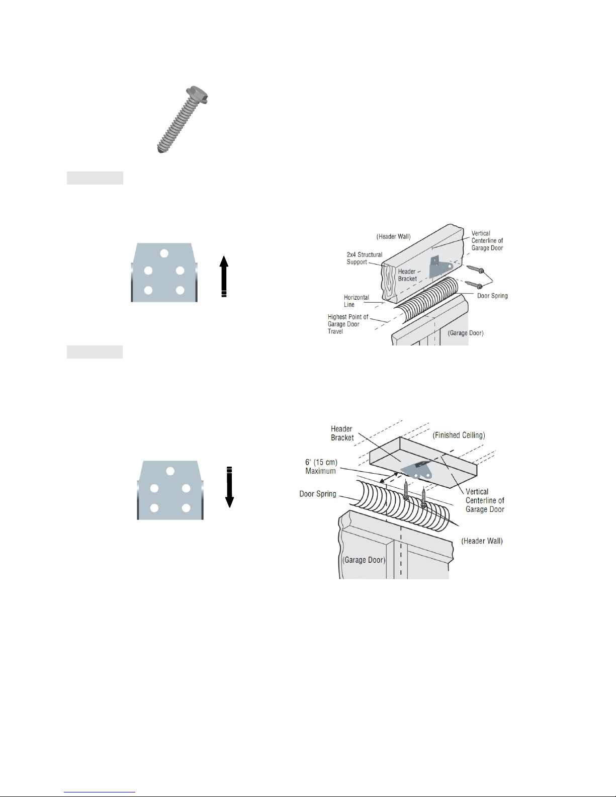
2、Install the Header Bracket
You can attach the header bracket either to the wall above the garage door, or to the ceiling. Follow the instructions which will
work best for your particular requirements. Do not install the header bracket over drywall. If installing into masonry, use
To prevent possible SERIOUS INJURY or DEATH:
· Header bracket MUST be RIGIDLY fastened to structural support on header wall or ceiling,
otherwise garage door might not reverse when required. DO NOT install header bracket over drywall.
· Concrete anchors MUST be used if mounting header bracket or 2x4 into masonry.
· NEVER try to loosen, move or adjust garage door, springs, cables, pulleys, brackets, or their hardware,
ALL of which are under EXTREME tension.
· ALWAYS call a trained door systems technician if garage door binds, sticks, or is out of balance. An
unbalanced
g
ara
g
e door mi
g
ht not reverse when re
q
uired.
12
concrete anchors (not provided).
HARDWARE:
Option A WALL INSTALLATION
2.1A Center the bracket on the vertical centerline with the bottom edge of the bracket on the horizontal line as shown (with the
arrow pointing toward the ceiling).
2.2A Mark the holes. Drill 3/16" pilot holes and fasten the bracket securely to a structural support with the hardware provided.
Option B CEILING INSTALLATION
2.1B Extend the vertical centerline onto the ceiling as shown.
2.2B Center the bracket on the vertical mark, no more than 6" (15 cm) from the wall. Make sure the arrow is pointing away
from the wall. The bracket can be mounted flush against the ceiling when clearance is minimal.
2.3B Mark the holes. Drill 3/16" pilot holes and fasten bracket securely to a structural support with the hardware provided.
INSTALLATION
3、Attach the Rail to the Header Bracket
3.1 Align the rail with the header bracket. Insert the clevis pin (H1) through the holes in the header racket and rail. Secure
with the cottor (H5).
H7
H7
H7 Lag Screw M8×40 (2)
H1 Clevis Pin, long
Φ8×80 (1) H5 CotterΦ2×25(1)

13
WARNING
HAEDWARE
4、Position the garage door opener
NOTE A 2x4 is ideal for setting the distance between the rail and the door. If the ladder is not tall enough you will need
help at this point.
If the door hits the trolley when it is raised, pull the trolley release arm down to disconnect the chain connector kit and trolley.
Slide the trolley toward the garage door opener. The trolley can remain disconnected until further instruction.
5、Hang the garage door opener
To avoid possible SERIOUS INJURY from a falling garage door opener, fasten it
SECURELY to structural supports of the garage. Concrete anchors MUST be used if
installing ANY brackets into masonry.
CAUTION
To prevent damage to garage door, rest garage door opener rail on 2x4
p
laced on to
p
section of door.
H5
H1
14
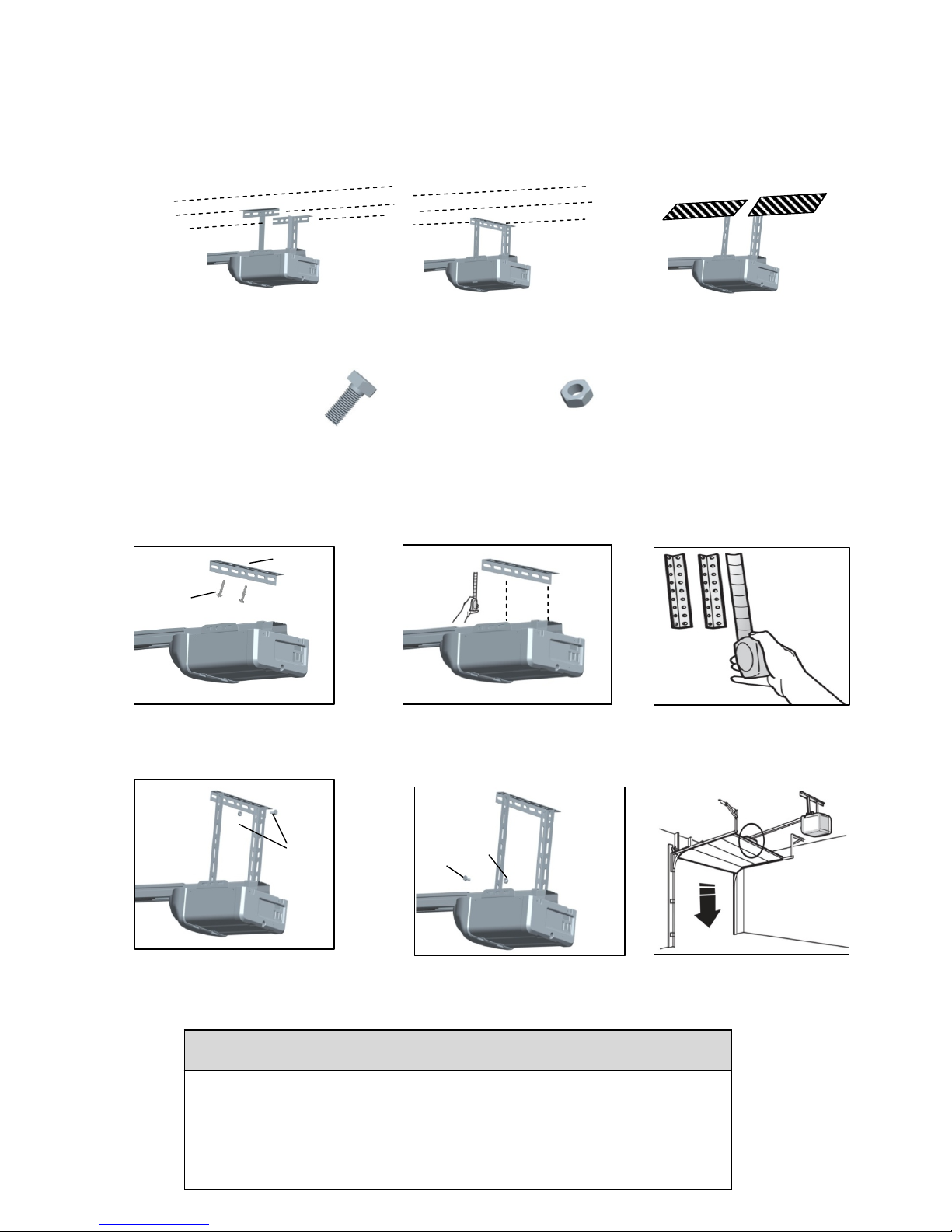
Hanging the garage door opener will vary depending on your garage. Below are three example installations. Your
installation may be different. For ALL installations the garage door opener MUST be connected to structural supports. The
instructions illustrate one of the examples below.
HARDWARE
6、Install the light bulbs
CAUTION
To prevent possible OVERHEATING of the end panel or light socket:
· Use ONLY A19 incandescent or compact fluorescent light bulbs.
· DO NOT use incandescent bulbs larger than 100W.
· DO NOT use compact fluorescent light bulbs larger than 26W (100W)equivalent.
· DO NOT use halogen bulbs.
· DO NOT use short neck or s
p
ecialt
y
li
g
ht bulbs.
Fi
n
i
s
h
e
d
C
e
ili
ng
U
n
f
i
n
i
s
h
e
d
C
e
ili
ng
5.1On finished ceilings, use the lag
screws (H7) to attach a support
bracket (not provided) to the
structural supports before installing
the garage door opener
5.2 Make sure the garage door opener
is aligned with the header bracket.
Measure the distance from each
side of the garage door opener to
the support bracket.
5.3 Cut both pieces of the hanging
b
racket to re
q
uired len
g
ths.
H7
Not
p
rovide
d
5.4 Attach the end of each hanging
aligned bracket to the support bracket
with appropriate hardware (not
provided).
5.5 Attach the garage door opener to
the hanging brackets with the bolts
(H15), lock washers (H21) and nuts
(H20).
5.6 Remove the 2x4 and manually close
the door. If the door hits the rail,
raise the header bracket.
Not
p
rovide
d
H4
H4 Hex Bolt M8×20(2) H3 Hex
N
ut
H3

15
WARNING
NOTE: The use of short neck or speciality light bulbs may overheat the end panel or light socket.
6.1 Pull the top sides of the light lens and rotate the light lens down.
6.2 Insert an A19 incandescent or compact fluorescent light bulb (100 watt maximum), into the light socket.
6.3 Clip the lens in the opener.
7、Attach the Emergency Release Rope and Handle
To prevent possible SERIOUS INJURY or DEATH from a falling garage door:
If possible, use emergency release handle to disengage trolley ONLY when garage
door is CLOSED. Weak or broken springs or unbalanced door could result in an open
door falling rapidly and/or unexpectedly.
NEVER use emergency release handle unless garage doorway is clear of persons and
obstructions.
NEVER use handle to pull door open or closed. If rope knot becomes untied, you
could fall
OR

16
NOTE:
If it is necessary to cut the emergency release rope, seal the cut end with a match or
lighter to prevent unraveling.
Ensure that the emergency release rope and handle are above
the top of all vehicles to avoid entanglement.
7.1 Insert one end of the emergency release rope through the handle. Tie a knot at least 1 inch (2.5 cm) from the end of the
emergency release rope.
7.2 Insert the other end of the emergency release rope through the hole in the trolley release arm. Make sure the handle is 6 feet
(1.83 m) above the floor and secure with a knot.
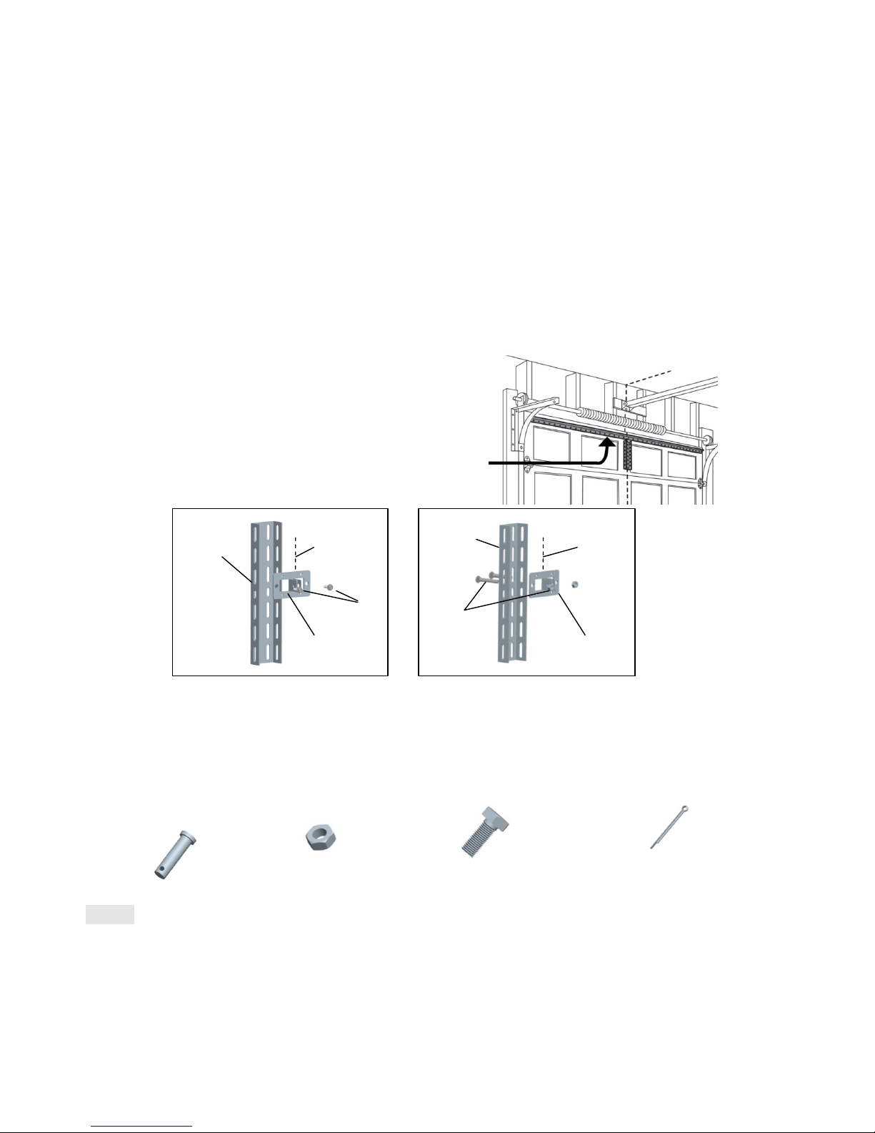
8、Install the door bracket
Figure 1 shows one piece of angle iron as the horizontal brace. For the vertical brace, 2 pieces of angle iron are used to
create a U-shaped support. The best solution is to check with your garage door manufacturer for an opener installation door
reinforcement kit.
NOTE: Many door reinforcement kits provide for direct attachment of the clevis pin and door arm. In this case you will not
need the door bracket; proceed to the next step.
HARDWARE
Option SECTIONAL DOORS
CAUTION
Fiberglass, aluminum or lightweight steel garage doors WILL REQUIRE reinforcement
BEFORE installation of door bracket. Contact your door manufacturer for reinforcement kit.
H8 Self-Threading Screw (2)
17
8.1A Center the door bracket on the previously marked vertical centerline used for the header bracket installation.
Note correct UP placement, as stamped inside the bracket.
8.2A Position the top edge of the bracket 2"-4" (5-10 cm) below the top edge of the door, OR directly below any
structural support across the top of the door.
8.3A Mark, drill holes and install as follows, depending on your door’s construction:
Metal or light weight doors using a vertical angle iron brace between the door panel support and the door bracket:
· Drill 3/16" fastening holes. Secure the door bracket using the two self-threading screws (H16). (Figure 2)
· Alternately, use two 5/16" bolts, lock washers and nuts (not provided). (Figure 3)
Metal, insulated or light weight factory reinforced doors:
· Drill 3/16" fastening holes. Secure the door bracket using the self-threading screws (H16). (Figure 4)
Wood Doors:
· Use top and bottom or side to side door bracket holes. Drill 5/16" holes through
the door and secure bracket with
5/16"x2" carriage bolts, lock washers and nuts
(not provided). (Figure 5)
NOTE:
The 1/4"-14x5/8" self-threading screws are not intended for use on wood
9、Connect the door arm to the trolly
HARDWARE
Option SECTIONAL DOORS
NOTE
:If the holes in the curved door arm and the straight door arm do not align, reverse the
straight door arm, select two
holes (as far apart as possible) and attach using bolts (H15), nuts (H20), and lock washers (H21).
A horizontal and vertical reinforcement is needed for
lightweight garage doors (fiberglass, aluminum, steel,
doors with glass panel, etc.) (not provided). A horizontal
reinforcement brace should be long enough to be secured to
two or three vertical supports. A vertical reinforcement
brace should cover the height of the top panel.
Vertical
Reinforceme
nt
Vertical Centerline
of Garage Door
H8
Vertical
Reinforcement
Vertical Centerline
of Garage Door
Bolt 5/16"
Nut 5/16"
(not provided)
H2 Clevis Pin,short
Φ8×30 (2)
H5 CotterΦ2×25(2)
H3 Hex
N
ut
M8(2) H4 Hex Bolt M8×20(4)
9.1 Close the door. Disconnect the rolley by
pulling the emergency release handle.
9.2 Attach the straight door arm to the outer trolley using
the clevis pin (H14). Attach with the ring fastener
(H19).
Door Bracket
Door Bracket

18
WARNING
If the straight door arm is hanging down too far, you may cut 6 inches (15 cm) from the solid end.
Install the Wall Control
1 Install the wall control
To prevent possible SERIOUS INJURY or DEATH from electrocution:
· Be sure power is NOT connected BEFORE installing door control.
· Connect ONLY to 24 VOLT low voltage wires.
To prevent possible SERIOUS INJURY or DEATH from a closing garage door:
· Install door control within sight of garage door, out of reach of children at a minimum height of 5 feet (1.5 m), and
away from ALL moving parts of door.
· NEVER permit children to operate or play with door control push buttons or remote control transmitters.
· Activate door ONLY when it can be seen clearly, is properly adjusted, and there are no
obstructions to door travel.
ALWAYS k
d i i ht til l t l l d NEVER it t th f l i
9.3 Attach the curved door arm to he door
bracket using the clevis pin (H13). Attach
with the ring fastener (H19).
9.4 Bring arm sections together. Find two pairs of
holes that line up and join sections. Select holes as far
apart as possible to increase door arm rigidity and
attach using the bolts (H15), nuts (H20) and lock
washers (H21).
9.5 Pull the emergency release handle toward
the garage door opener until the trolley
release arm is horizontal. The trolley will
re-engage automatically when the garage
door opener is activated.
H5
H2
H5
H2
H4
H3
H4
H3

19
INTRODUCTION
Install the wall control within sight of the door at a minimum height of 5 feet (1.5 m)
where small children cannot reach, and
away
from the moving parts of the door.
Your product may look different than
the illustrations.
HARDWARE
NOTE: For gang box installations it is not necessary to drill holes or install the drywall anchors. Use the existing holes in the
gang box.
2 Wire the wall control to the garage door opener
Drywall Anchors (2) Screw M4×30 (2)
1.1、Strip 7/16 inch (11 mm) of
insulation from one end of the
wire and separate the wires.
1.2、Open the bottom of the wall
control
1.3、Connect the white wire to
the #3 screw ,connect the black
\white wire to the #4 screw .
1.4、Mark the location of the
bottom mounting hole and drill
a 6 mm hole.
1.5、Insert and tighten screws to
secure the bottom of the control to
wall
1.6、Position the wall panel onto
the bottom.
2.1、Strip 7/16 inch (11 mm) of
insulation from one end of the wire and
separate the wires.
2.2、Connect the white wire to the #3
terminal and the black\white wire to the #4
terminal on garage door opener.

20
WARNING
3Attach the warning labels
3.1 Attach the entrapment warning label on the wall near the door control with tacks or staples.
3.2 Attach the manual release/safety reverse test label in a visible location on the inside of the garage door.
Install The Photo Eye Safety System
Introduction
Be sure power is NOT connected to the garage door opener BEFORE installing the safety reversing sensor.
To prevent SERIOUS INJURY or DEATH from a closing garage door:
· Correctly connect and align the safety reversing sensor. This required safety device MUST NOT be
disabled.
I ll h f i b i NO HIGHER h 6" (15 ) b fl
To insert or remove the wires from
the terminal, push in the tab with a
screwdriver tip.
Other manuals for 9357
1
This manual suits for next models
1
Table of contents
Other Seaside Garage Door Opener manuals

Popular Garage Door Opener manuals by other brands


Cardin Elettronica
Cardin Elettronica 311/GL124EBSS instruction manual

UNAC
UNAC BFT FLC 8K2 Installation and user manual

Assa Abloy
Assa Abloy SL300 user manual

Raynor
Raynor 3245RGD 1/3 HP owner's manual

Smart Openers
Smart Openers Smart Roller Shutter installation manual

Challenger
Challenger 9300M Installation and owner's manual


