Seatec AIS6 User manual
User Manual
AIS6 / MFR6

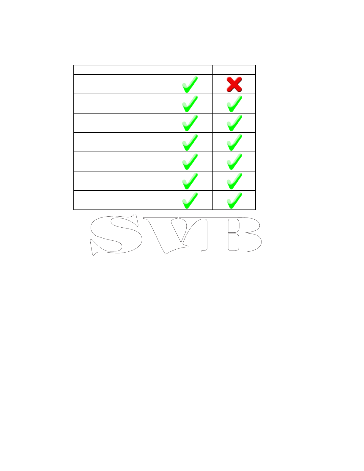
Important Features at a glance
Below you will find a brief summary of the main features of your Seatec AIS6 / MFR6. Your Seatec AIS6 /
MFR6 will be your reliable partner for a safe navigation at sea.
Integrated AIS Receiver (only AIS6)
Integrated VHF Splitter (only AIS6)
AIS Screen
AIS List of Ships
AIS SART Warningssystem
NMEA Multifunctiondisplay
1
SEATEC - AIS6 / MFR6
Thank you for choosing a device of the Seatec product range. The Seatec devices offer an extraordinary de-
gree of reliability combined with an excellent way of use. Seatec offers exceptional technologies and highest
quality standards.
AIS6
The Seatec AIS6 offers you the possibility to receive AIS signals and display them on a brilliant, high-resolu-
tion display. The AIS targets will be displayed on a so-called “AIS radar screen”. Detailed information of the
received AIS targets can be viewed on a clearly structured AIS detail list.
Another great feature of the AIS6 is the handling of the received AIS SART signals. The Seatec AIS6/MFR
allows you to recognize AIS SART signals quickly. When your AIS6 receives an AIS SART signal this will be
displayed visually and in the form of an acoustic warning. Many AIS SART transmitter allow to send out an
AIS SART TEST signal. In order to quickly distinguish between a test and a real emergency signal, TEST sig-
nals are displayed differently (as a green symbol ref. page 19) on the AIS screen of your device.
Because of this groundbreaking technology of your Seatec device, the safety of all parties at sea is signifi-
cantly increased.
The rescue manoeuvre can start immediately after receiving a “real” AIS SART signal.
MFR6
The Seatec Multifunction Repeater (MFR6) is a seamless addition to your existing navigation devices.
The MFR6 displays incoming NMEA data, such as wind-, GPS-, depth-, speed-, autopilot- and AIS data. The
received data will be displayed on your usual Seatec screens. You can, for example, use the MFR6 on lower
deck in combination with a Seatec AIS6 placed on the flybridge.
2
Feature AIS6 MFR6
Integrated VHF Splier
AIS Screen
AIS SART Warning System
AIS List of Ships
Wind Display (NMEA)
Highway (NMEA)
Compass

SEATEC - AIS Applications
The Seatec AIS devices can be integrated in almost any NMEA board system so that received AIS data can
be transferred to other AIS enabled devices. Seatec devices can also display other NMEA data such as
depth, log, wind and autopilot data.
This turns your Seatec device into a true multi-functional display. Important data can quickly and easily be
displayed. You can get a fast overview of the needed data.
The built-in VHF splitter of your AIS6 permits you to use your existing VHF antenna for both; AIS reception
and for your VHF-Radio. Beneath you will find a connection example for your AIS6 device.
AIS-,wind-,depth-,
Speed, Temp. Data
3
UKW-Antenna
(receiving AIS and VHF)
UKW-Antenna cable
Depth, Speed,Temp.
Winddata
GPS Data
GPS Data

Directory
1............................................Frontview and Key´s
2............................................Backview and cable assignment
2.1......................................AIS6
2.3.....................................MFR6
3............................................Screens / Views
3.1.......................................AIS Screen
3.1.1...............................AIS List of Ships
3.1.2..............................AIS Menu
3.2......................................Compass
3.3......................................Wind Display
3.4......................................Highway
3.5......................................Multidata Display
4............................................Main Menu Settings
5............................................AIS SART
5.1......................................AIS SART Test
6............................................Technical Specifications
4

1. MENU
Press the menu key shortly to open the menu of the current screen of your device
2. MODE
With the mode key you can switch between different windows:
• AIS Screen (displaying the received AIS targets)
• Compass (shows the current course through GPS)
• Wind indication (shows winddata received by NMEA)
• Highway (shows autopilot data received by NMEA)
• Multifunction display (SOG, SPD, Depth, Power)
3. Cursor-Pad
With the Cursor-Pad you can navigate through the menu and move the cursor on the
AIS Screen.
4. ENT
Confirms the current selection and shows AIS details of the selected AIS target.
5. ESC
Closing of windows / exit of current menu.
Hint: Use ESC to move a window back (invers MODE function)
6. MOB
This key is not engaged
7. F
The function key shows the “type-of-ship” overview on your AIS screen.
8. POWER
Press and hold to turn the device on /off
9. ZOOM IN / ZOOM OUT
Zoom into/zoom out of the AIS screen
10. Display
Displays all information clearly and reliably
1Front View and Key´s
The Seatec AIS devices have a varity of important funtions and features. The key mapping
of your AIS6 device has been optimized so that you can easily edit all settings and operate
safely and quickly even on rough sea.
5
1
2
3
4
5
6
7
8
9
10
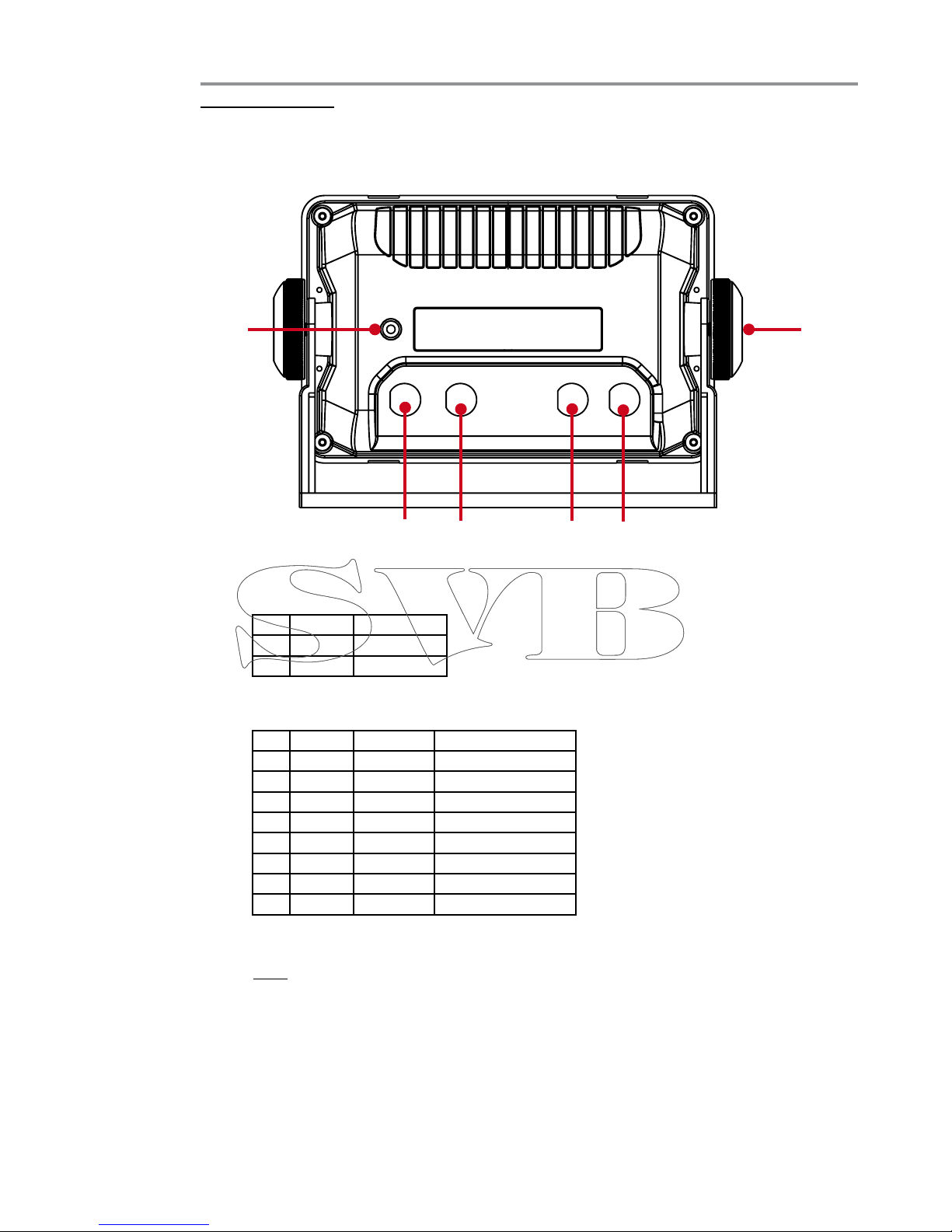
Back view and cable assignment
2
2.1 AIS6
1. Connection for power supply
Here you can connect the supplied 2-Pin powercable which includes a build-in 0.5A
fuse.
Pin Color Descripon
1 Black - 12 / 24 Volt DC
2 White + 12 / 24 Volt DC
2. Datacable Connector
To insert or retrieve NMEA data, you need to connect the datacable here.
Pin Color Baudrate Descripon
1 Brown 4.800 NMEA Input +
2Red 4.800 NMEA Input +
3 Orange 4.800 NMEA Input +
4 Yellow 4.800 NMEA Input +
5 Green - NMEA Input - (Ground)
6 Blue 38.400 NMEA Output +
7 Purple - Opon
8 White - NMEA Output - (Ground)
3. VHF Antenna IN
Connect your VHF Antenna here (P/L Plug).
Hint: We recommend the VHF-Antenna RA106 (SVB-Art.: 73101)
4. VHF Antenna OUT
Connect your VHF here.
Normally you will need a P/L - P/L connection cable (SVB Art. No.: 95508).
Great connectivity!
The Seatec technology is based on proven and reliable data communication methods. This in-
cludes the sending of AIS NMEA data and receiving of wind, autopilot, depth and speed data.
These information can be integrated from external devices.
5. Thumbscrews
The two included thumbscrews are used to secure the device with the mounting
bracket. This allows also an “upside-down” mounting.
6. Electrical grounding
To avoid mutual interference, the unit must be grounded.
6
1 2 3 4
56
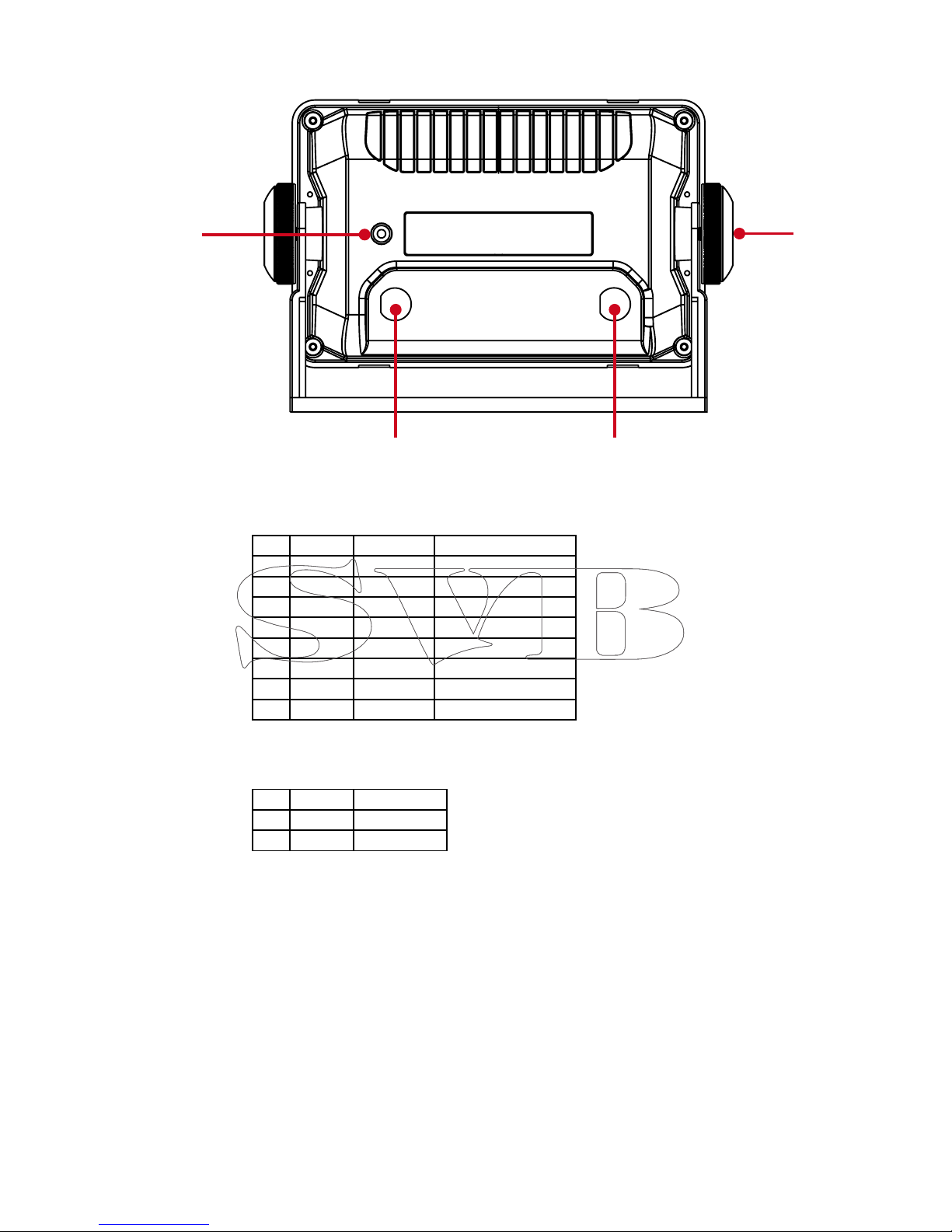
2.3 MFR6
1. Datacable Connector
To insert and retrieve NMEA data, you need to connect the data cable here.
Pin Color Baudrate Descripon
1 Brown 4.800 NMEA Input +
2Red 4.800 NMEA Input +
3 Orange 4.800 NMEA Input +
4 Yellow 4.800 NMEA Input +
5 Green - NMEA Input - (Ground)
6 Blue 38.400 NMEA Output +
7 Purple 38.400 AIS NMEA Input +
8 White - NMEA Output - (Ground)
2. Power Connector
You can connect the supplied 2-Pin powercable which includes a build-in 0.5A, here.
Pin Color Descripon
1 Black - 12 / 24 Volt DC
2 White + 12 / 24 Volt DC
4. Electrical grounding
To avoid mutual interference, the unit must be grounded.
3. Thumbscrews
The two included thumbscrews are used to secure the device with the mounting
bracket. This allows also an “upside down” mounting.
7
1 2
3
4

Screen / Views
33.1 AIS Screen
1. AIS Screen
This is the main screen of your Seatec AIS device. Here you will find all received AIS
targets displayed on a radar-like screen.
• Move the cursor above any AIS target to show important ship information.
• You can reduce and enlarge the display range using the Zoom IN / OUT zoom
keys /. The current zoom level of your device can be seen in the lower left cor-
ner named “Range” (5).
Additional Functions:
• Press the “F” (7) button to call-up the AIS ship-
type index.
Every received signal contains information about
the type of ship. On the right side you will find an
overview of the AIS ship types.
Hint: Press “ENT” (4) to open detailed informationen (ref.to chapter 3.1.1)
Hint: To use the AIS screen it is necessary to connect an external GPS antenna. You can
use any GPS device that has a NMEA0813 output.
8
1

2. AIS Reception LED
The Seatec AIS units are equipped with virtual reception LEDs. They start blinking
when a class A or B AIS signal has been received.
Class A: Signals of this class are sent mainly from commercial shipping.
These signals contain more information than Class B signals.
Class B: These signals are normally transmitted by sport boats and contain
basic information about the boat.
You will find a detailed list of the class A and B signals in chapter 3.1.1
Hint: Use the LED´s to check the function of the AIS receiver.
3. AIS Alarm Field
This field shows the distance (CPA) and the time (TCPA) to the next AIS alarm.
For more information about AIS alarms CPA and TCPA, see chapter 3.1.2
4. Data Field
Display of basic information such as position, speed over ground (SOG), course over
ground (COG) and depth (received via NMEA).
5. Range / CPA-Ring
Range shows, in which radius AIS targets are displayed.
The CPA ring indicates the radius in which a CPA alarm will be activated for an AIS
target. For more information on the CPA alarm, see chapter 3.1.2
6. Date / Time
Displays the current date and time (in UTC format), which is transmitted by the GPS
receiver.
9
5
4
3
2
6

3.1.1 AIS List of ships
The AIS list of ships shows all received AIS targets in one table. You can see the total num-
ber of received targets and you have access to detailed information of these targets.
To open the AIS list of ships you need to be on the AIS Screen (ref. to chapter 3.1) , then
press “Menu” (1) and choose the point “AIS Detail List”. Confirm your choice by pressing
“ENT” (4).
1. Received Targets
Shows the number of received targets.
If the number is >20 your device indicates that more AIS targets are received than
could be displayed on the first page. In this case you can scroll down by using the
▼, ▲- (3) keys.
2. Colums of the AIS List of Ships
The AIS list of ships is divided neatly into the following columns:
No. = Consecutive number of individual AIS targets. Sorted by distance.
NATION = Shows the flag under which the AIS target moves (depends on the
MMSI of the vessel)
MMSI = Shows the MMSI of the vessel
NAME = Displays the ship name
DIST (NM) = Distance between your GPS position and the AIS target.
SOG (kts) = Current speed of the AIS target (kn)
COG = Shows the course of the AIS target
TYPE = Displays the AIS class (A / B)
10
2
1

From the AIS list of ships you can choose a single target using the ▼, ▲- (3) buttons.
Once you have selected the desired ship, press “ENT” (4) for detailed information about
this AIS target.
Depending on the ship class A or B (see AIS list, column “TYPE”) there are different ship
information. Likewise, you can call up information about an AtoN.
A Class A signal contains the following information:
• Ship name
• Country
• Ship typ
• MMSI
• Call-sign
• Current position
• Speed (SOG)
• Course (COG)
• CPA Alarm
• TCPA Alarm
• Position of the GPS
Antenna
Besides class B signal information, a Class A signal contains the following data:
• ROT (Rate of turn)
• Destination
• ETA (Eastimated time of arrival)
• NAV Status
- Underway using engine
- Moored
- Limited maneuverability
- At anchor
- Not under command
- Grounded
- Engaged in fishing
• Length, width and draft of the vessel
Information about an AtoN (Navigation support)
An AtoN can characterise different objects, such as
virtual tons, drilling platforms, windparks, etc.
The AtoN signal contains the following informations:
• Name of the AtoN
• Type of AtoN
Virtual (for example, virtual ton) or real (Windpark)
• Spezification
• MMSI of the AtoN
• Position of the AtoN
• Position of the GPS Antenna
• Dimensions of the AtoN (Lenght/Width)
11
“ENT” (4)
Press the “menu” (1) button to enter the AIS menu. You can now edit the following settings:
• CPA Limit
Here you can adjust the radius of the CPA ring.
CPA (Closest Point of Approach) describes the distance between your
current position and the AIS target before it becomes a threat to you.
3.1.2 AIS Menu
• CPA Limit ON/OFF
Turns the CPA alarm on or off.
• TCPA Limit
Here you can setup the time for the TCPA Alarm.
TCPA (Time to closest point of approach) describes the time until the next
CPA becomes active.
• TCPA Limit ON/OFF
Turns the CPA alarm on or off.
• AIS Detail List
Here you can open the AIS list of ships (ref. to chapter 3.1.1.)
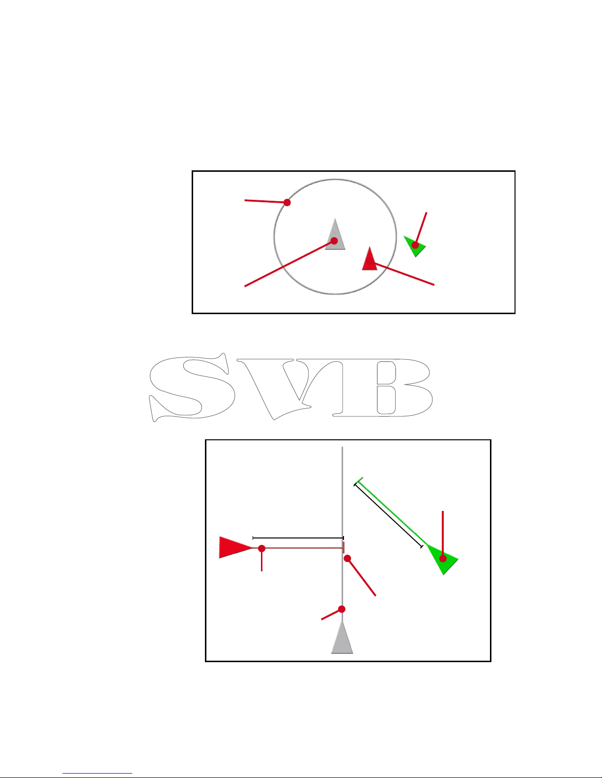
12
Own course line
Course line of
AIS target
10 min.
10 min.
The TCPA alarm is
triggered, because the
course line of the AIS
target will cross your
line in 10 min.
The TCPA alarm
is not triggered
because the own
course line won´t
be crossed
Your own
position AIS target acti-
vates the CPA
alarm
AIS target doesn´t acti-
vate the CPA Alarm.
CPA-Ring
e.g. 5nm
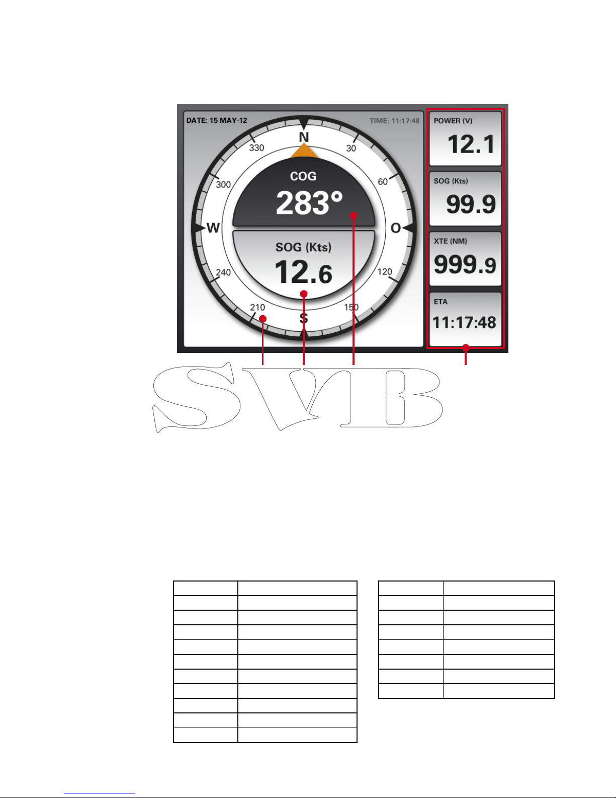
1. Compass
Graphical display of the current GPS course.
2. Speed over ground (SOG)
Displays the current speed over ground, which is received via GPS.
3. Course over ground (COG)
Shows the current course over ground received by the GPS.
4. Data field
This display pannel can be adjusted to your preferences.
Press the menu button to get to “data field setup”. Once you confirm with ENT, a
framework will surround the first data field. Use the cursor keys to choose the data
field you would like to edit and press “ENT” (4).
A list from which you can select your disired data will open up.
Confirm your selection with “ENT” (4).
3.2 Compass
Posion Current GPS posion
TTG Time to the next waypoint
Bearing Bearing to the next waypoint
Range Distance to the next WP
SOG Speed over ground
COG Course over ground
XTE Course track error
ETA Esmated me of arrival
Date Time Date and Time by GPS (UTC)
Voltage Power
Depth Depth (mtr.)
Speed Speed through water
Water Temp. Water temperature
AWA Apparent wind direcon
AWS Apparent wind speed
TWA True wind direcon
TWS True wind speed
Wind Dir. Wind direcon
VMG > True wind speed
The Seatec product range offers a clear display of the compass data received from the GPS.
Additionally you can display further important information on the data field.
13
1 2 3 4

3.3 Wind Display
1. Winddirection
Graphical display of the wind data received by NMEA.
2. True wind speed (TWS)
Shows the current true wind speed received by NMEA.
3. Apparent wind speed (AWS)
Apparent wind speed received by NMEA
4. Data field
These display panels can be adjusted to your liking.
Press the menu button to get to the point “data field setup”. Once you confirm with
ENT, a framework will surround the first data field. Use the cursor keys to select
the data field you would like to edit and press “ENT” (4).
A list from which you can select your desired data will open up.
Confirm your selection with “ENT” (4).
Using the marine NMEA 0183 data protocol, wind data can be imported from external instru-
ments into the Seatec devices. The received data is presented on a structured display.
Posion Current GPS posion
TTG Time to the next waypoint
Bearing Bearing to the next waypoint
Range Distance to the next WP
SOG Speed over ground
COG Course over ground
XTE Course track error
ETA Esmated me of arrival
Date Time Date and me by GPS (UTC)
Voltage Power
Depth Depth (mtr.)
Speed Speed through water
Water Temp. Water temperature
AWA Apparent wind direcon
AWS Apparent wind speed
TWA True wind direcon
TWS True wind speed
Wind Dir. Wind direcon
VMG > True wind speed
14
1 2 3 4

3.4 Highway
1. Waypoint Name
Displays the name of the waypoint, which is being driven.
2. Next Waypoint
Shows the position of the next waypoint.
3. Graphical display of cross track error (XTE)
Here you can see the current deviation of the ideal course.
You can use the ZOOM (9) buttons to adjust the range.
4. ETA (Estimated time of arrival)
Tells you when you will reach your next waypoint.
5. XTE (Measured cross track error)
Here you can see the current deviation of your ideal course.
6. Data field
Press the menu button to get to the point “data field setup”. Once you confirm
with ENT, a framework sets to the first data field, use the cursor keys to choose the
data field you want to edit and press “ENT” (4).
There is a list that opens and from which you can select the desired data.
Confirm your selection with “ENT” (4).
Many autopilotes offer the possibility to send data via NMEA to Seatec devices. Incoming
autopilot NMEA data is represented professionally in the highway view.
Posion Current GPS posion
TTG Time to the next waypoint
Bearing Bearing to the next waypoint
Range Distance to the next WP
SOG Speed over ground
COG Course over ground
XTE Course track error
ETA Esmated me of arrival
Date Time Date and Time by GPS (UTC)
Voltage Power
Depth Depth (mtr.)
Speed Speed through water
Water Temp. Water temperature
AWA Apparent wind direcon
AWS Apparent wind speed
TWA True wind direcon
TWS True wind speed
Wind Dir. Wind direcon
VMG > True wind speed
15
4 5 6
1
2
3
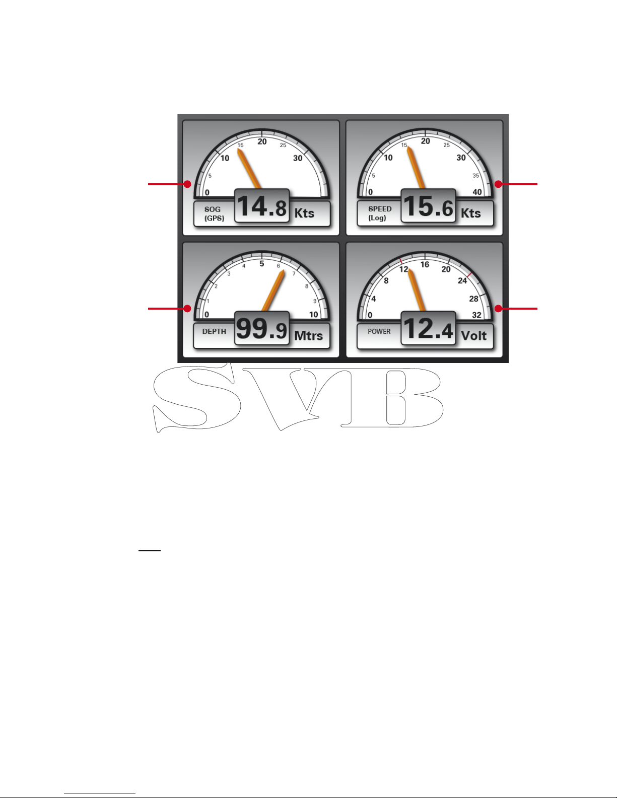
3.5 Multidatadisplay
The Seatec products provide incoming NMEA data such as speed over ground (SOG), water
speed (log) and depth (Depth) presented in a structured data field. Moreover, the currently
applied voltage is displayed on the device.
1. Speed over ground (SOG)
Represents the current speed over ground (SOG), which is transmitted through the
GPS receiver.
2. Depth
Represents the current depth, which is received via the NMEA interface.
3. Speed though water (Log)
Displays the current speed through the water (Log), which is received via the NMEA
interface.
4. Power (Volt)
Shows the current voltage applied to the device.
Hint: For transmitting log, depth and water temperature data, we recommend a NMEA
triducer (SVB-Art.: 98515).
16
1
2
3
4

Main Menu Settings
4In the main menu of Seatec AIS devices you can edit basic settings, set alarms and show
incoming NMEA data sets.
To access the main menu, press the “Menu” (1) button twice. Now you have access to the
following settings:
Setup
Here you can edit the following settings of your device:
- Adjustment of various units, such as knots and nautical miles
- Time and date configuration
- Turning the simulation modus on/off
- Changing the system language
- Turnung the key sounds on / off
- Restore to factory defaults
Alarm
Under this menu point you have the option to configure different alarms.
Press the “ENT” (4) button to switch an alarm signal on or off.
Anchor Alarm
This lets you set and monitor your position in relation to an anchor point.
Until you leave this point of the distance you set an alarm will be triggered.
Press the “ENT” (4) button to switch an alarm on or off.
Speed Alarm
The speed alarm can be set for speeds that is greater than a certain number
of knots (high) or below a certain number of knots (low).
Timer
Sets a time until an alarm will occure.
Buzzer
You can choose between a short-, long- and constant alarm tone
Warning Message
Here you have the possibility to call a history of all received alarms.
NMEA Data
This feature allows you to show all the NMEA data, which was received via
your external interface.
17

AIS SART
5Your Seatec AIS6/MFR6 is one of the devices on the market that is capable of an acoustic
and visual alert for incoming AIS SART signals. In addition to that, the position of the AIS
SART signal will be displayed on the AIS screen. Therefore, you can easily navigate to the
position of the AIS SART signal.
Process after an AIS SART signal was received:
• Once an AIS SART signal was received, the following message appears on the display of
your AIS6 / MFR6 and you will hear an alarm tone.
• The AIS6 / MFR6 beeps until this screen has been confirmed by pressing the “ENT” (4)
key. After confirming, the window will close and the position of the AIS SART signal will
be displayed on the AIS screen.
• Access detailed information of the AIS SART signal by moving the cursor over the AIS
SART symbol and press the “ENT” (4) button.
- MMSI of the AIS SART transmitter
- The position of the AIS SART transmitter
- The date and time when the AIS SART signal has been received for the first time.
- Speed over ground (SOG) of the AIS SART Signal
- Course over ground of the (COG) AIS SART Signal
- Distance between your position and the position of the AIS SART signal
- Course/direction from your position to the AIS SART Signal.
This window shows the following information:
18
AIS SART Symbol
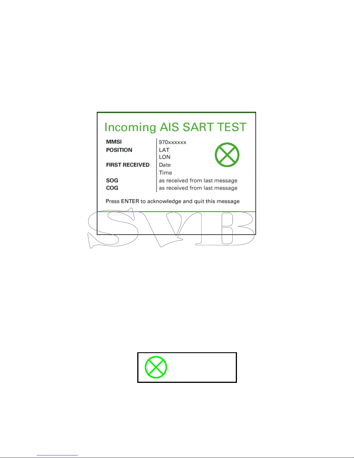
5.1 AIS SART Test
Many AIS SART transmitters have a “test” button, which checks the functioning of the trans-
mitter. When pressing the “test” button, an “AIS-SART TEST” signal is sent out by the trans-
mitter.
To help you distinguish between a test and a real AIS SART signal, the Seatec AIS devices
display whether this signal is a test message or a real message.
Once a test message is received, an audible alarm appears accompanied by the following
message:
The AIS SART TEST window contains the following information:
Press the “ENT” (4) button to disable the audible alarm and close the window. You can
review the title and time of the received AIS SART test signal under “warnings” in the Alarm
menu (ref. Chapter 4).
- MMSI of the AIS SART transmitter
- The position of the AIS SART transmitter
- The date and time when the AIS SART signal was received for the first time.
- Speed over ground (SOG) of the AIS SART Signal
- Course over ground of the (COG) AIS SART Signal
Once the window is closed, the AIS SART TEST signal is displayed on the AIS screen as a
green symbol:
19
AIS SART TEST Symbol
This manual suits for next models
1
Table of contents
Popular Marine GPS System manuals by other brands


Blue Sky Network
Blue Sky Network SKYLINK user guide

SperryMarine
SperryMarine NAVIKNOT 600 SD Operation, installation and service manual

Iridium
Iridium 9575 quick guide

Nera
Nera BGAN NERA WorldPro 1000 Getting started guide

Flightcell
Flightcell Iridium 9555 Cradle Mk 4 installation manual

Satellite Hire
Satellite Hire Iridium 9505A user guide


