5Place the device in the bail-mount bracket, and tighten the
bail-mount knobs.
Securing the Device
You can lock the device to the structure of your boat for added
security (optional).
1Bail-mount the device (page 1).
2Using a coated braided-steel cable (not included) and a lock
(not included), secure the back of the case À to the structure
of the boat.
Flush Mounting the Device
NOTICE
Be careful when cutting the hole to flush mount the device.
There is only a small amount of clearance between the case
and the mounting holes, and cutting the hole too large could
compromise the stability of the device after it is mounted.
The included template and hardware can be used to flush
mount the device in your dashboard. To mount the device so
the screen is flat with the dashboard, you must purchase a flat-
mount kit from your Garmin® dealer.
1Trim the template and make sure it fits in the location where
you want to flush mount the device.
2Remove the protective liner from the back of the template
and adhere it to the location where you want to mount the
device.
3Using a ½ in. (13 mm) drill bit, drill one or more of the holes
inside the corners of the solid line on the template to prepare
the mounting surface for cutting.
4Using a jigsaw, cut the mounting surface along the inside of
the solid line indicated on the template.
5Place the device in the cutout to test the fit.
6If necessary, use a file and sandpaper to refine the size of
the cutout.
7After the device fits correctly in the cutout, ensure the
mounting holes on the device line up with the larger 9/32 in.
(7.2 mm) holes on the template.
8If the mounting holes on the device do not line up, mark the
new hole locations.
9Using a 9/32 in. (7.2 mm) drill bit, drill the larger holes.
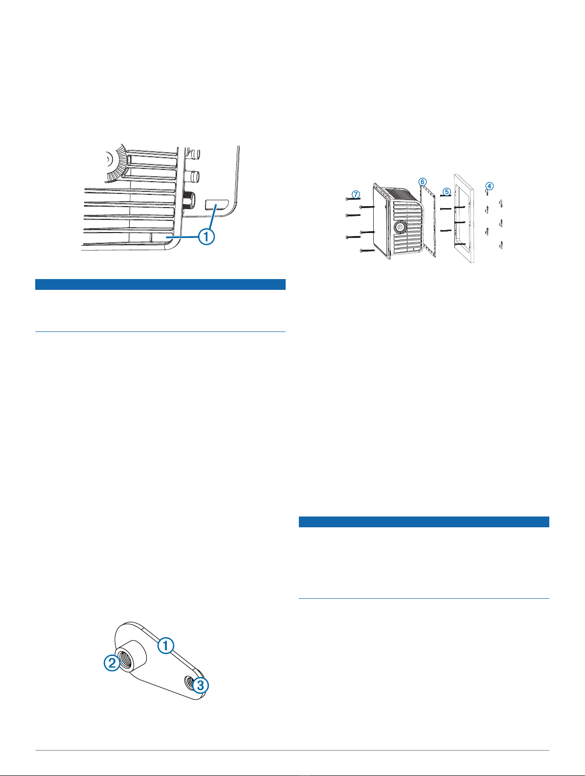
10Starting in one corner of the template, place a nut plate À
over the larger hole Á drilled in step 9.
The smaller 9/64 in. (3.5 mm) hole  on the nut plate should
line up with the smaller hole on the template.
11If the smaller 9/64 in. (3.5 mm) hole on the nut plate does not
line up with the smaller hole on the template, mark the new
hole location.
12Repeat steps 10–11 for each of the nut plates along the
sides of the device as indicated on the template.
13Using a 9/64 in. (3.5 mm) drill bit, drill the smaller holes.
14Remove the template from the mounting surface.
15Starting in one corner of the mounting location, place a nut
plate à on the back of the mounting surface, lining up the
large and small holes.
The raised portion of the nut plate should fit into the larger
hole.
16Secure the nut plate to the mounting surface by fastening an
included M3 screw Ä through the smaller 9/64 in. (3.5 mm)
hole.
17Repeat steps 15–16 for each of the nut plates along the
sides of the device.
18Install the rubber gasket Å on the back of the device.
The pieces of the rubber gasket have adhesive on the back.
Make sure you remove the protective liner before installing
them on the device.
19If you will not have access to the back of the device after you
mount it, connect all necessary cables to the device before
placing it into the cutout.
NOTE: To prevent corrosion of the metal contacts, cover
unused connectors with the attached weather caps.
20Place the device into the cutout.
21Secure the device to the mounting surface using the included
M4 screws Æ.
22Insert the included plugs over each of the M4 screw heads.
23Install the decorative bezel by snapping it in place around the
edges of the device.
Card Reader Mounting Considerations
NOTICE
This device should be mounted in a location that is not exposed
to extreme temperatures or conditions. The temperature range
for this device is listed in the product specifications. Extended
exposure to temperatures exceeding the specified temperature
range, in storage or operating conditions, may cause device
failure. Extreme-temperature-induced damage and related
consequences are not covered by the warranty.
The card reader can be flush mounted in the dashboard using
the included hardware. When selecting a mounting location,
observe these considerations.
• The card reader should be mounted in an accessible
location. You must be able to access the card reader when
necessary to insert and remove memory cards containing
additional mapping and device updates, and to transfer user
data.
• To avoid interference with a magnetic compass, the device
should not be installed closer to a compass than the
compass-safe distance value listed in the product
specifications.
2


