Wideye Sabre Shield User manual

SABRE™
SHIELD
Rev 1.0

1
SABRETM Shield Installation Guide
Copyright
Warranty
Trademarks

SABRETM Shield Installation Guide
2
Congratulations on the purchase of your SABRETM I Remote terminal and
SABRETM Shield.
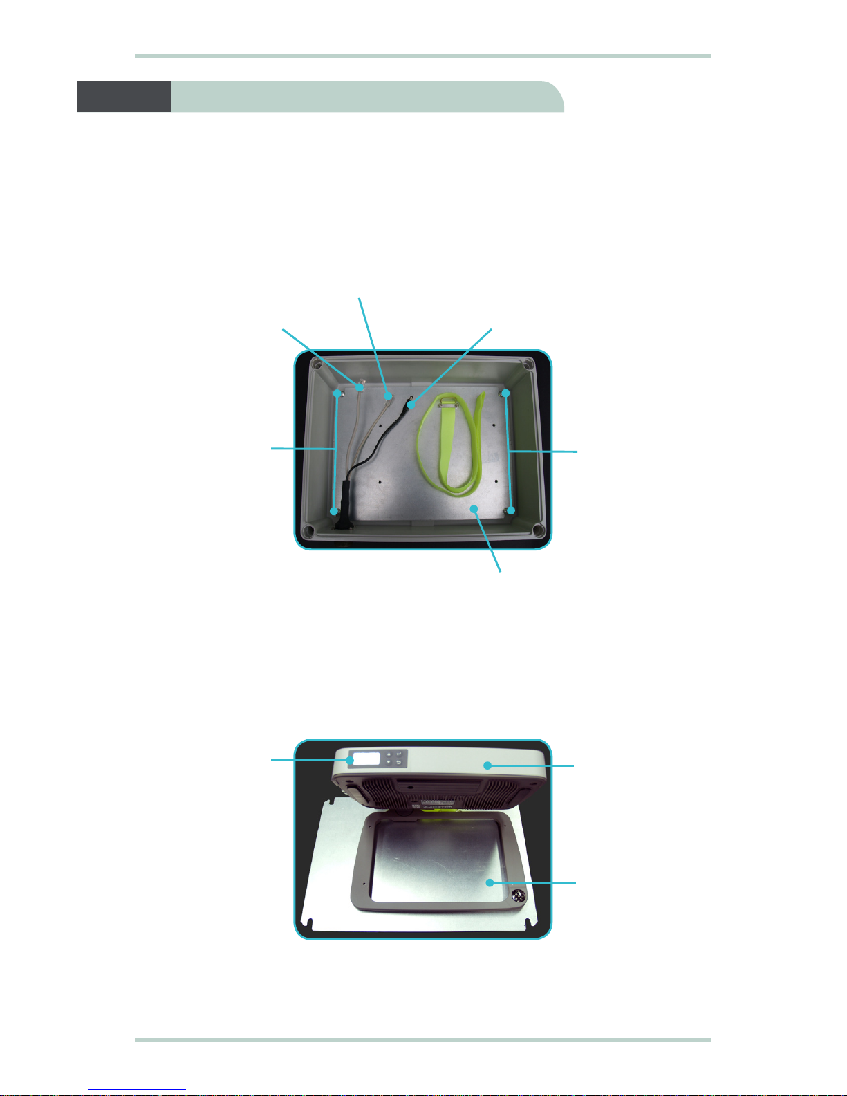
When you unpack the package, please check that the following items are
present:
ySABRETM I Remote terminal
ySABRETM Shield
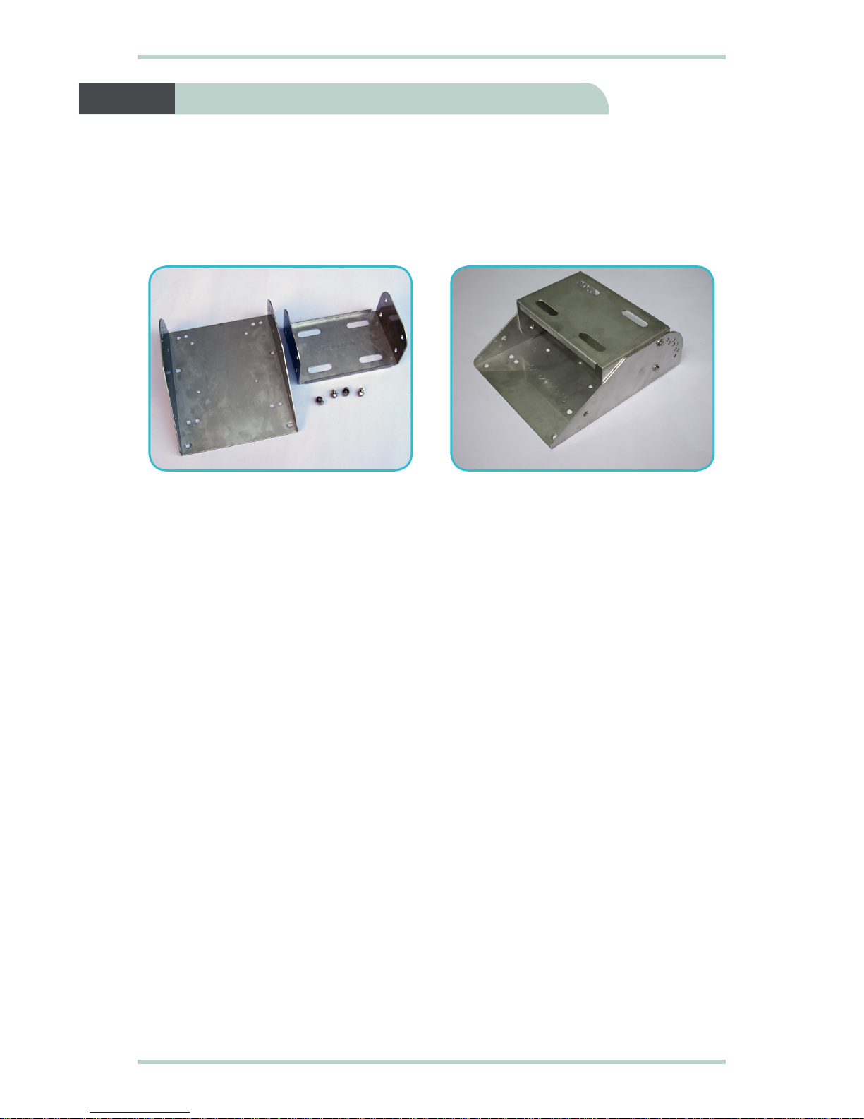
yMounting Plate (including four allen screws with nuts and washers)
yMounting Frame (including four bolts with nuts and washers)
yTwo U-bolts with four washers and nuts
yFour screws (to secure terminal to base plate)
yAC/DC power adapter with power cable
yEthernet cable (RJ45, Cat 5 Straight, 1.5m)
yPhone cable (RJ11, 1.8m)
yMulti-function cable (10 metres)
yInstallation guide
yProduct CD (software utilities and documentations)
If any of the items are missing from the package, please contact your
reseller where you have purchased the SABRETM I Remote terminal and
SABRETM Shield package.
1 Getting Started

3
SABRETM Shield Installation Guide
Follow these steps to remove the battery door:
1. Place your thumbs on the battery door as shown.
2. Push the battery door outwards in the direction shown.
2 Removing the Battery Door
Follow the step to remove the battery:
1. Release clip and remove the battery in the direction shown.
3 Removing the Battery
Battery

SABRETM Shield Installation Guide
4
4 Installing SIM Card
Follow these steps to install the SIM card:
1. Insert the SIM card into the SIM slot with the gold-contacts facing out.
2. Push the SIM card in until it clicks and lock in place.
Note:
To remove the SIM card, push SIM card in. The SIM card will spring up and
then remove from the slot.
SIM card
5 Installing the Battery Door
Follow these steps to install the battery door:
1. Align the battery door with the guiding rail as ahown.
2. Slide the battery door in along the guiding rail until it clicks and lock in
place.

5
SABRETM Shield Installation Guide
Follow these steps to prepare the SABRE™ Shield:
1. Place the SABRE™ Shield on a flat surface.
2. Release the four cover screws and remove the cover.
3. Release the velcro-tape securing the Multi-function cable.
4. Remove the Multi-function cable from the SABRE™ Shield.
5. Remove the pack of screws, bolts, nuts and washers from the SABRE™ Shield
and keep them in a safe place.
6 Preparing the SABRE™ Shield
Multi-function
cable
Cover
Cover
Screws
Cover
screws
Multi-function
cable connector

SABRETM Shield Installation Guide
6
Follow these steps to install the SABRETM I Remote terminal inside the SABRETM
Shield:
1. Remove four screws securing base plate to the SABRETM Shield.
2. Remove the base plate from the SABRETM Shield.
3. Place the SABRETM I Remote terminal on the base plate with the LCD screen
facing towards you (as shown below).
4. Turn over the base plate together with the SABRETM I Remote terminal.
7 Installing SABRE™ I Remote
Base plate
Base plate
SABRETM I
Remote
terminal
LCD screen
Ethernet (RJ45)
cable connector
Phone (RJ11)
cable connector
Power plug
Screws
Screws

7
SABRETM Shield Installation Guide
5. InstallfourscrewstosecuretheSABRETM IRemoteterminaltothebaseplate.
6. Using the velcro-tape, secure the SABRETM I Remote terminal to the base
plate as shown below.
Base plate
Velcro-tape
Screws
Screws
uv
w
x

SABRETM Shield Installation Guide
8
7. Install the base plate back to the SABRETM Shield.
8. Install four screws to secure the base plate to the SABRETM Shield.
9. Insert the power plug into the DC power input socket on the SABRETM I
Remote terminal.
10. Insert the connector end of the Phone cable to the SABRETM I Remote
terminal Analog Phone (RJ11) port.
11. Insert the connector end of the Ethernet cable to the SABRETM I Remote
terminal Ethernet (RJ45) port.
DC power input socket
Analog phone (RJ11) port
Ethernet (RJ45) port
Screws
Screws

9
SABRETM Shield Installation Guide
Follow these steps to setup the mounting frame:
1. Align the mounting frame.
2. Install four bolts with washers to secure the mounting frame together.
8 Setting Up the Mounting Frame

SABRETM Shield Installation Guide
10
Follow these steps to install the mounting frame to the mounting plate:
1. Place mounting plate on the back of the mounting frame.
2. Place four nuts onto the four grooves located on the mounting plate.
3. Install four bolts with washers to secure mounting frame to the mounting
plate.
9 Installing Mounting Frame to
Mounting Plate
Mounting
frame
Mounting
plate
Grooves
Grooves
Bolts with
washers Bolts with
washers

11
SABRETM Shield Installation Guide
Follow these steps to install the mounting plate to the SABRETM Shield:
1. Place SABRETM Shield on top of the mounting plate as shown below.
2. Drop the four allen screws to the four slot holes at each corner of the
SABRETM Shield.
3. Fasten the four nuts with washers to secure SABRETM Shield to the mounting
plate.
10 Installing Mounting Plate to SABRE™ Shield
Slot holes
Slot holes
Nuts with
washers
Nuts with
washers

SABRETM Shield Installation Guide
12
4. Install the SABRETM Shield cover.
5. Tighten the the four cover screws to secure the SABRETM Shield cover.
Cover
Screws
Cover
screws

13
SABRETM Shield Installation Guide
11 Mounting the SABRETM Shield
Follow these steps to mount the SABRETM Shield:
1. Locate a vertical pole or column to mount the SABRETM Shield.
2. Mount the SABRETM Shield to the vertical pole or column using two U-bolts,
four nuts and washers.
3. Tighten the four nuts evenly to secure the SABRETM Shield terminal to the
vertical pole or column.
SABRETM
Shield
Lock bolt for
elevation Secure the
U-Bolt to
vertical pipe
or pole

SABRETM Shield Installation Guide
14
4. Install the Multi-function cable header to the connector on the SABRETM
Shield.
Follow these steps to position the SABRETM Shield:
1. Remove two lock bolts and nuts on either side of the mounting frame.
2. Adjust the elevation of the SABRETM Shield and secure its position using the
two lock bolts and nuts on either side of the mounting frame.
3. Secure the length of the Multi-function cable to the pole or column using
cable ties.
Note:
Ensure there is some slack at both ends of the Multi-function cable to avoid any
stress build-up, which may damage the cable.
Lock bolt for
elevation
12 Positioning the SABRETM Shield
Multi-function
cable header

15
SABRETM Shield Installation Guide
Follow these steps to power up the SABRETM I Remote terminal:
1. Insertthe poweradapter outputplug intothe DCpower inputsocket onthe
Multi-function cable.
2. Insert the plug end of the power adapter into an AC outlet.
3. Turn on the power to power up the SABRETM I Remote terminal.
Multi-function
cable
DC power
input cable
Ethernet port
Phone port
DC power
input
socket
13 Powering Up the SABRETM I Remote

SABRETM Shield Installation Guide
16
Follow these steps to connect the SABRETM I Remote terminal to your computer
using Ethernet:
1. Insert one connector end of the Ethernet cable to the Multi-function cable’s
Ethernet port.
2. Insert the other connector end of the Ethernet cable to your computer’s
Ethernet port.
A message confirming connection is displayed on your computer.
14 Connecting to your Computer via Ethernet

17
SABRETM Shield Installation Guide
The BGAN network requires valid GPS co-ordinates to successfully register your
SABRETM I Remote terminal for the first time or after you have performed a
Factory Reset. The terminal will perform the GPS acquisition automatically.
Follow these steps to obtain GPS co-ordinates:
1. Ensure that the SABRETM I Remote terminal is facing upwards and with an
open view of the sky.
2. Start your Internet browser.
3. Type http://192.168.1.35 in the Address field and press Enter.
The Connect to 192.168.1.35 login screen appears.
4. Type in admin in the Username field and wideye in the Password field.
Click OK.
15 Obtaining GPS Co-ordinates

SABRETM Shield Installation Guide
18
5. The SABRETM I Web Console will appear on your screen.
6. Allow the terminal a few minutes to acquire the GPS co-ordinates.
Once the GPS co-ordinates is acquired, the New GPS acquired message is
displayed.
Note:
The GPS co-ordinates will not be displayed until you click Register Network
toregistertoInmarsat’sBGANnetwork.TheGPSdisplayprohibitedmessage
willbedisplayediftheGPScoordinatesareprohibitedbytheBGAN network.
It is recommended to register to the BGAN network after acquiring new GPS
co-ordinates before powering down the terminal. This will ensure the GPS
co-ordinates are stored in the terminal’s memory.

19
SABRETM Shield Installation Guide
Establishing a connection with the BGAN network requires the careful
orientation of the SABRETM I Remote terminal towards the satellite, a process
called antenna pointing.
To perform antenna pointing, you will need a compass and the following
information from the Web Console:
yPointing Angle (Azimuth and Elevation)
ySignal stength indicator bar
With the SABRE™ I Web Console launched, follow these steps to register with
the network:
1. Select the satellite that you want the SABRETM I Remote terminal to point to.
2. Rotate the terminal left or right until it points in the correct horizontal
direction as indicated in the Azimuth reading with the aid of a compass.
3. Tilt the terminal slowly up or down until it points in the correct vertical
direction as indicated in the Elevation reading.
4. With the aid of the Signal indicator bar on the Web Console, fine tune the
pointing direction to obtain the maximum signal strength.
16 Registering with the BGAN Network
This manual suits for next models
1
Table of contents
Other Wideye Marine GPS System manuals