Globalstar FAU200 SAT System manual

Fixed Access Unit (FAU)
for Globalstar Systems
FAU200 SAT
Installation Handbook

The product described in this manual conforms to the 98/13/EC Telecommunications Terminal
Equipment (TTE) and Satellite Earth Station Equipment (SESE) Directive, the 89/336/EEC EMC Directive
and the 73/23/EEC Low Voltage Directive.
This device complies with part 15 of the FCC Rules. Operation is subject to the following two conditions: (1)
This device may not cause harmful interference, and (2) this device must accept any interference received,
including interference that may cause undesired operation.
First Edition: April 2000
This manual is published by Globalstar L.P. “AS IS” WITHOUT ANY WARRANTY. Improvements and
changes to this manual required by typographical errors, inaccuracies, or improvements to programs and /
or equipment, may be made by Globalstar LP, at any time and without notice. Such changes will, however,
be incorporated into new editions of this manual.
All rights reserved. No part of this document may be reproduced in any form without the written permission
of the copyright holder.
© 2000 Ericsson Mobile Communications (UK) Limited
Publication number: EN/LZT 123 5050 R2

FAU Installation Handbook
c
SAFETY
Warnings
DANGER:
EARTH LEAKAGE CURRENTS
Under no circumstances should the
FAU be operated without a protective
earthing conductor.
DANGER:
HAZARDOUS VOLTAGES
Hazardous voltages will be present
within the FAU once power has been
applied.
DANGER:
HAZARDOUS VOLTAGES
Avoid electrical contact with the
telephone wires, hazardous voltages
may be present.
WARNING:
DANGER TO PERSONNEL
The FAU may fall down if it is
incorrectly mounted on pole.
WARNING:
HOT COMPONENTS
The FAU case will become hot when
working and care must be taken
when handling a unit that has just
been switched off.
WARNING:
DANGER TO PERSONNEL
Ensure the FAU is securely mounted
before powering-up.

FAU Installation Handbook
d
THIS PAGE INTENTIONALLY LEFT BLANK

FAU Installation Handbook
i
Contents
General ............................................................................................. 1
Definitions and Abbreviations .............................................................................1
Product Description ........................................................................ 2
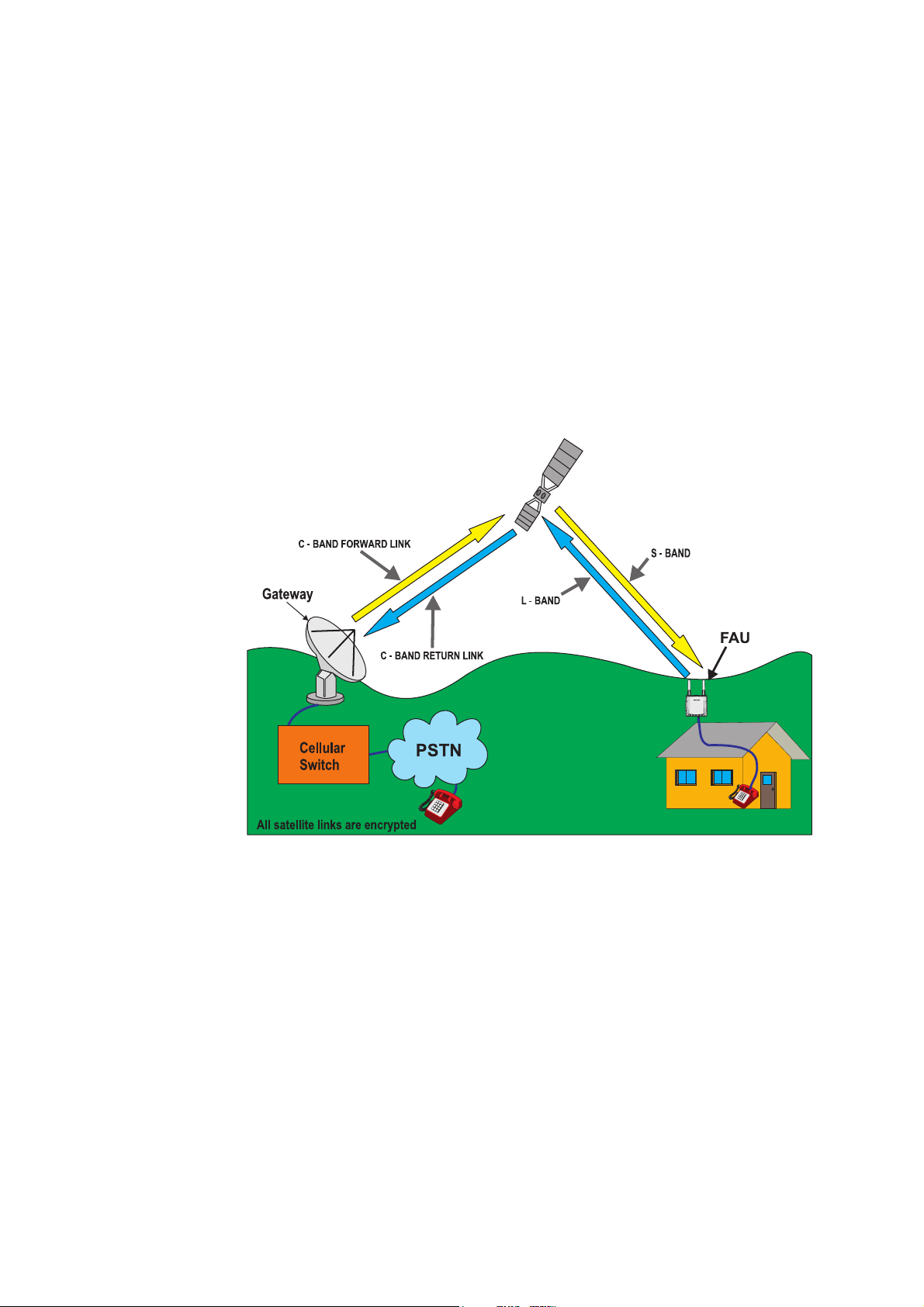
Globalstar System ................................................................................................2
Fixed Access Unit (FAU) ....................................................................................2
Pre-Installation ................................................................................. 3
Pre-Installation Planning ......................................................................................3
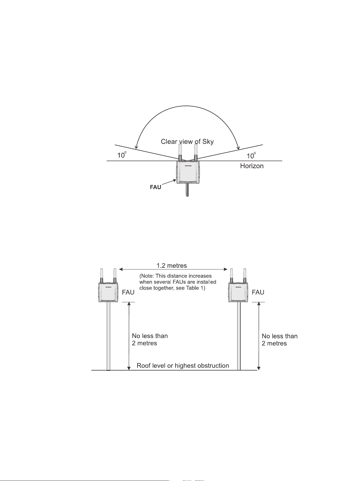
Planning the Location for the FAU ................................................................4
Radio Interference Sources (for Guidance Only) ...........................................5
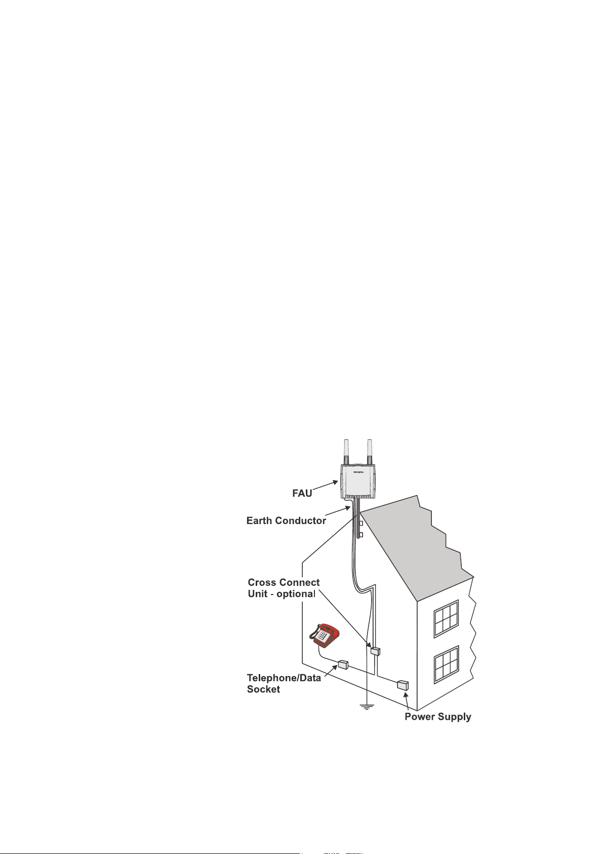
Cable Routing .................................................................................................5
Lightning Protection .......................................................................................6
Switched DC Power Supply ............................................................................6
Pole Mounting ................................................................................................7
Preparatory field engineering work .....................................................................7
Preparation and Configuration of the FAU ..........................................................7
Installation ....................................................................................... 9
Assembling the FAU ...........................................................................................9
Fitting the FAU ..................................................................................................10
FAU Connections ..............................................................................................12
Telephone ( ■) .............................................................................................13
Power (✝●) ...................................................................................................13
Data ( ▲) .....................................................................................................14
PDI (✝✖) ......................................................................................................14
SAFETY - Earth/Ground ..............................................................................14
Commissioning 15
Power-Up ...........................................................................................................15
Making a test call ...............................................................................................15
Receiving an Incoming Test Call .......................................................................15
Emergency Calls ................................................................................................16
Reset Functions ..................................................................................................16
Data Calls ...........................................................................................................16
Fault Finding ......................................................................................................17
Technical Data - FAU ..................................................................... 18
Physical ..............................................................................................................19
Power requirements ...........................................................................................19
Environmental ....................................................................................................19
Interfaces 19
Air interface ..................................................................................................19
Installation .........................................................................................................20
Standards ............................................................................................................20
Technical Data - PSU ........................................................................................20
Technical Data - Cables .....................................................................................20
Cable between FAU and PSU ......................................................................20
Cable between FAU and cross-connect ........................................................21
Protective Earth Cable (typical) ...................................................................21
Additional Information .................................................................................21
Patents 22

FAU Installation Handbook
ii
APPENDIX 23
Additional Cable Information and Typical Installation Details ........................ 23
Additional Specifications for Cables and Connectors ................................. 24
Typical Wall and Pole Mounting of the FAU .............................................. 26

FAU Installation Handbook
1
General
The FAU is a device to enable the end user to make and receive telephone calls via
the Globalstar satellite network. This handbook describes how to plan the
installation, fit the FAU and prepare it for use. Please read the safety information
carefully. This issue covers the residential and PABX versions of the FAU only.
Definitions and Abbreviations
AC Alternating Current
ACB All Circuits Busy
ANSI American National Standards Institute
AWG American Wire Gauge
BTS Base Transmitting Station
CHS Circular Hollow Section
dB Decibels
dB/K Decibels per degree Kelvin
dBm Decibel referred to 1 mW
DC Direct Current
DTMF Dual Tone Multi-Frequency
EIA Electronic Industries Association
EIRP Effective Isotropic Radiated Power
FAU Fixed Access Unit for Globalstar network
GAI Globalstar Air Interface
Hz Hertz
IP Ingress Protection
ITU International Telecommunications Union
LEO Low Earth Orbit
LNA Low Noise Amplifier
Nm Newton-metres
P(A)BX Private (Automatic) Branch Exchange
PDI Production & Development Interface
PIN Personal Identity Number
PSTN Public Switched Telephone Network
REN Ringer Equivalence Number
RMS Root Mean Square
SIM Subscriber Identity Module
TIA Telecommunications Industry Association
TTE Telecommunications Terminal Equipment
WM2 A PC-based Windows software tool for testing and configuring the FAU

FAU Installation Handbook
2
Product Description
Globalstar System
Globalstar is a low earth orbit (LEO) satellite-based telecommunications network
offering wireless telephone services worldwide. The Fixed Access Unit (FAU)
provides an interface for the end-user to access the Globalstar satellite network.
The FAU communicates using the Globalstar Air Interface (GAI) via the satellite
constellation to a number of groundstations or Gateways.
The gateway interconnects the Globalstar satellite network through a Cellular Switch
directly into the local Public Switched Telephone Network (PSTN). A diagram of the
Globalstar network is shown below.
The FAU is installed outdoors to provide an unobstructed view of the orbiting
satellite constellation, and cabling is run from the unit to a conventional telephone
socket mounted indoors, for easy connection of a telephone.
Typical Satellite Link
Fixed Access Unit (FAU)
The FAU comprises a single unit formed from a die-cast aluminium case enclosed
on four sides by moulded polycarbonate sunshields. Access to the single circuit
board contained within the aluminium case, is via the removable aluminium
backplate. The plate is secured using tamper-proof fixings.
Twin antennas - transmit and receive - attach to the top of the case using captive
screw fixings. The receive antenna incorporates a Low Noise Amplifier (LNA).
The mechanical design of the FAU is common to two applications and provides the
end user with an interface for connecting a standard telephone:
• Residential FAU - allowing connection of a telephone.
• PABX FAU - allowing connection of a range of PABXs.

FAU Installation Handbook
3
Pre-Installation
The following activities will need to be carried out, before installation and
commissioning of the FAU at the subscriber’s site:
• Pre-installation Planning.
• Preparatory Field Engineering Work.
• Preparation and configuration of the FAU at the Engineering Depot.
Pre-Installation Planning
Pre-installation planning activities may include:
• Survey of subscriber location, address and mains voltage.
• Identify mounting location for FAU and type of pole/mast/wall fixing.
• Confirm position of the FAU is acceptable with customer/service provider.
• Identify position of possible interfering transmissions. This could be fixed
service microwave transmissions, radar pulses or a cellular base station.
• Identify position for FAU safety earthing system.
• Identify location for 48 V DC power supply.
• Identify position of any cross-connect unit/junction box and telephone socket.
• Determine and gain appropriate planning approval for the following cable
routes:
FAU - subscribers premises.
FAU - power supply.
Typical FAU installation

FAU Installation Handbook
4
Planning the Location for the FAU
When deciding on the location for the FAU attention should be paid to the following
planning recommendations:
• The FAU should be mounted to have a clear view of the sky, away from any
interfering sources or obstructions, see Figure below.
• The installation must be planned to place all equipment, cables, etc., out of reach
of the general public.
Clear View for Satellite Communication
• If the FAU is mounted on a building it must be at a minimum height of 2 metres
above the top of buildings with a clear view of the sky.
• Where two or three FAUs are to be mounted in the same area, they should be
separated by at least 1.2 metres. When there are more than three FAUs in the
same area, refer to Table 1 for recommended separation distances.
FAU Spacing and Clearance

FAU Installation Handbook
5
Radio Interference Sources (for Guidance Only)
In general the FAU will be unaffected by radio transmissions operating in the vicinity
of an installation. However, there are a small number of situations close to radio
transmitters where care should be taken in assessing the suitability of the site for
installing an FAU. If due care is not taken possible mis-operation of the FAU may
result or, in extreme cases, even damage.
NOTE: The information given is for guidance only. Worst case conditions have been
assumed throughout.
General Radar
An FAU may suffer damage if placed closer than:
•250 m of a general radar station operating near to the FAU receive band.
•150 m of a general radar station operating in the 5 GHz region.
Fixed Radio Services Operating in the FAU Receive Band
An FAU may be rendered inoperable if placed closer than:
•150 m from the centre boresight of a digital point-to-point microwave radio link.
•700 m of a digital point-to-multipoint base station using an omni-directional
antenna.
Cable Routing
The recommended cable types for use with the FAU allow the following maximum
separations:
Cable between FAU and DC Power Supply
For all applications, the cable between the FAU and its DC power supply should be
kept as short as possible, up to a maximum separation of 50 metres using standard
power cable. See Technical Data - Cables, for recommended cable types. Refer to
“Power Cable Lengths” on page 24 for relationship between cable gauge and
maximum length.
Table 1: FAU Separation Distances
Number of
FAUs
Distance from Nearest
FAU
21.2m
31.2m
41.5m
52.1m
62.1m
72.7m
83.4m
93.9m
10 4.5 m
11 5.1 m
12 6.0 m

FAU Installation Handbook
6
FAU Block Diagram
Cable between FAU and Telecommunication Terminal Apparatus
Residential applications <1.6 km (voice only).
PABX applications <1.6 km (voice only).
NOTE: This is the total length for all cabling to telephones including extensions.
FAU Applications
Lightning Protection
Consideration should be given to protecting all external power and
telecommunication cabling against lightning especially where long lengths of
overhead cable will be run from the FAU to terminal apparatus.
Where lightning protection is considered necessary all protective devices should be
fitted in accordance with local regulations.
Switched DC Power Supply
The unit must incorporate a disconnection device to allow the unit to be isolated from
the primary power source.
1.6 km (1 mile)
50 metres

FAU Installation Handbook
7
It is recommended that the DC power supply unit incorporates its own ON/OFF
switch to allow the FAU to be powered ON and OFF remotely.
Pole Mounting
The FAU can be mounted on a standard pole, see Technical Data and Appendix.
The following maximum stub pole free lengths are supported subject to the local in-
country regulations.
• 1.5 metres maximum for nominal 50 mm diameter stub pole.
• 3 metres maximum for nominal 100 mm diameter stub pole.
NOTE: Since the FAU should be mounted at least 2m above the roof level or highest
obstruction (see “Planning the Location for the FAU” on page 4) the 50mm diameter
stub pole should only be used as a “jockey pole”, i.e. fitted to a mast. See “Typical
Wall and Pole Mounting of the FAU” on page 26 for an example.
Preparatory Field Engineering Work
The following checklist details some of the main engineering field activities, which
may need to have been completed before installing the FAU:
• Erection of mast / pole.
• Installation of the cross-connect box and line-jack socket(s) at the subscribers
premises/PABX installation.
• Cabling of AC mains supply to DC Power Supply Unit, if applicable.
• Installation of DC Power Supply Unit and any stand-by power supply.
• Installation of data and telephony cabling from FAU to payphone/residence.
• Installation of power supply cabling from FAU to DC power supply unit.
• Provision of earthing system for FAU.
Preparation and Configuration of the FAU
Preparation and configuration of the FAU at the installer’s depot is essential before
field installation can take place.
The following checklist details the pre-requisite activities to be carried out for each
FAU:
• Unpack the FAU and check all packaged contents, refer to check list enclosed in
packaging.
• Allocate SIM card to FAU.
• Place FAU on earthing mat, connect earth lead and attach earthing strap to wrist.
• Using the Torx tools provided in the Installation Kit, remove the rear cover plate
from FAU, to access the SIM holder.

FAU Installation Handbook
8
• Insert the SIM into the holder as follows. Click the holder up in the direction of
the arrow, swing open, insert the SIM into the slot notch up as shown, fold back
down and click closed.
SIM Card Holder
• Attach the FAU Dongle and Dongle lead to a PC running the FAU200
Installation and Configuration Software (WM2). If required, use WM2 to
download application-specific software and software configurable parameters
(including the SIM PIN) to the FAU. For further information, see the WM2
Getting Started manual.
• As required, record the FAU and subscriber details, e.g. application, software
version, telephone number, SIM number, SIM PIN, FAU serial number, IMEI
number.
• Disconnect cables, fit the dust cap on the PDI connector, fit the rear cover and
tighten the securing screws to 2.5 Nm torque.
• Re-pack the FAU.

FAU Installation Handbook
9
Installation
Check the unit for transit damage and verify that the rear cover is secure. Cross check
that the FAU identity number (IMEI number) on the base of the unit, is the one
allocated to the subscriber.
FAU Label
Assembling the FAU
Sun shields and antennas must be fitted to the FAU housing before fitting the unit to
a pole.
NOTE: Both front and rear sun shields must always be fitted.
1. Place the front sun shield in position on housing ensuring it locates correctly
with screw holes.
2. Position the rear sun shields and insert four screws through rear sun shield and
housing into front sun shield.
3. Tighten screws in turn to 0.8-1.0 Nm torque. Do not overtighten these screws or
the sun shields could be damaged.
Fitting Sun Shields
4. Insert sealing ‘O’ rings into antenna sockets of main housing.
5. Place both antennas in position; they are keyed to ensure correct location of each
antenna and mating of antenna connectors.
6. Secure the antennas using the captive screws and tighten to 0.8-1.0 Nm torque.

FAU Installation Handbook
10
Fitting the Antenna
Fitting the FAU
The installer will first need to decide the appropriate method for installing the FAU,
see Pre-Installation.
1. Where conditions allow, mount the FAU on a pre-installed stub pole or mast, by
using the handle provided on the FAU. Typically, these situations will arise only
where the top of the pole can be reached safely and easily. Connection of cables
will then be possible after the FAU has been secured in position.
WARNING:
DANGER TO PERSONNEL
Do not install the FAU during a
lightning storm.
WARNING:
HAZARDOUS VOLTAGES
Use caution when installing or
modifying telephone lines as
hazardous voltages may be present.

FAU Installation Handbook
11
2. In situations where the top of the pole cannot be reached safely; FAU mounting
may be better achieved by mounting the FAU to the stub pole, connecting all
cables and then erecting and securing to the mast with the FAU in position.
The following procedure may need to be adapted to suit the chosen method of
installation:
1. Prepare the FAU for mounting at the top of the pole by loosely fitting the two
pole-clamps on the back of the FAU. The screw length will depend on the diam-
eter of the pole, e.g. a nominal 100 mm pole uses an 80 mm long screw, and a
nominal 50 mm pole uses a 25 mm long screw.
2. Lift the FAU over the top of the pole passing the pole through both brackets until
the top of the pole butts fully against the FAU handle/stop-plate, see below.
3. Secure the FAU to the pole by tightening the clamp bolts to 3±0.5 Nm torque.
FAU Pole Mounting
WARNING:
DANGER TO PERSONNEL
The FAU may fall down if it is
incorrectly mounted on pole.
WARNING:
DANGER TO PERSONNEL
Ensure the FAU is securely mounted
before powering-up.

FAU Installation Handbook
12
FAU Connections
Each FAU has seven external Connections:
• Antenna Rx.
• Antenna Tx.
• Bolt - Earthing cable.
• Connector - 2-wire telephony cable.
• Connector - data cable - not used.
• Connector - 2-wire DC power feed.
• Connector - PDI cable for configuration and commissioning.
FAU Connections

FAU Installation Handbook
13
Telephone ( ■)
The drawing below shows the pin connections of the socket.
1. Unscrew the castellated locking ring on connector to remove the 2-pin insert.
(You can use the dust cover as a wrench to unscrew the locking ring.)
2. Slacken the cable-clamping nut and insert the cable into the connector.
3. Connect the appropriate wires to pins L and N of the 2-pin insert, and then
tighten the securing screws.
4. Replace the insert and then tighten the castellated locking ring and cable clamp.
5. Plug into the FAU and tighten the retaining ring.
Telephone Line Connections
The telephone cable should be supported at regular intervals along its route according
to local regulations. Typically, a fixing every 300 mm or so is common. P-Clips or
All Weather Ty-wraps are generally used for this but whatever supports are chosen
must be suitable for the cable diameter and chosen to suit the surface or surfaces at
that particular site. Waterproof sealant should be used to seal and weather-proof the
point of entry of the cable into the building following local installation standards.
Ensure the installation is aesthetically pleasing.
Power ( ●)
The drawing below shows the pin connections of the power socket. Refer to “Power
Cable Lengths” on page 24 for the relationship between the cable gauge and the
maximum length.
1. Unscrew the castellated locking ring on connector to remove the 2-pin insert.
(You can use the dust cover as a wrench to unscrew the locking ring.)
2. Slacken the the cable-clamping nut and insert the cable into the connector.
3. Connect the appropriate wires to sockets L and N and tighten the securing
screws.
Table 2: Cable Connectors
Manufacturer: Bulgin Type: Buccaneer sealed
Connector No of ways
required Bulk head Connector Cable Connector - Flex
Mounting (not supplied)
PDI 25-way Panel Plug - fitted
with 25-way crimp
pin insert.
Socket - fitted with
25-way crimp pin
insert.
Data 25-way Panel Socket -
fitted with 25-way
crimp pin insert.
Plug - fitted with
25-way crimp pin
insert.
Power 2-way Panel Plug - fitted
with 2-way screw
type terminal.
Socket - fitted with
2-way screw type
terminal.
Telephone Line
(A & B lines)
2-way Panel Socket - fitted
with 2-way screw
type terminal.
Plug - fitted with 2-way
screw type terminal.
Pin No. Function
L A (Tip)
N B (Ring)

FAU Installation Handbook
14
4. Replace the insert and then tighten the castellated locking ring and cable clamp.
5. Plug into the FAU and tighten the retaining ring.
The power source should provide +48 volts DC with respect to the FAU case. The
power cable should be supported at regular intervals along its route according to local
regulations. Waterproof sealant should be used to seal and weatherproof the point of
entry of the cable into the building following local installation standards.
Power Socket Connections
Data ( ▲)
The data connector is not used in this version of the FAU. Ensure the dust cap is
securely fitted to protect the FAU from dust and moisture ingress.
PDI ( ✖)
The PDI cable enters a socket at the base of the FAU. When the socket is not in use,
ensure that the dust cap is securely fitted to protect the FAU from dust and moisture
ingress.
NOTE: There is no supplementary surge protection on the PDI port in addition to that
normally provided on an RS232 port.
SAFETY - Earth/Ground
The FAU enclosure must be connected to a single protective earth. A separate copper
earth cable must be installed from the FAU to an earth / ground, in accordance with
local regulations.
Earthing Connection
Ensure the earthing conductor is attached to the housing as shown above using
toothed washer to provide good contact.
DANGER:
EARTH LEAKAGE CURRENTS
Under no circumstances shall the
FAU be operated without a protective
copper earthing conductor.
EARTHING CABLE
WITH RING TAG
(NOT SUPPLIED)
M6 EARTHING BOLT
EXTERNAL
TOOTHED
WASHER
Table of contents
Other Globalstar Marine GPS System manuals

Globalstar
Globalstar GSP-1700 User manual

Globalstar
Globalstar 9600 User manual

Globalstar
Globalstar GSP-2800 User manual

Globalstar
Globalstar GSP 1600 User manual

Globalstar
Globalstar GSP-1700 User manual

Globalstar
Globalstar GSP-2900 Operating instructions

Globalstar
Globalstar Qualcomm GSP-1600 User manual

Globalstar
Globalstar Qualcomm GSP-1600 User manual