Seatex DPS 200 User manual

Seatex DPS 200
Installation Manual
Issued: 2003-03-06
FSP ref.: A11213500XRBRA0

Blank page
FSP ref.: A11213500XRBRA0

III
Notice
•All rights reserved. Reproduction of any of this manual in any form whatsoever without
prior written permission from Kongsberg Seatex AS is forbidden.
•The contents of this manual are subject to change without notice.
•All efforts have been made to ensure the accuracy of the contents of this manual.
However, should any errors be detected, Kongsberg Seatex AS would greatly appreciate
being informed of them.
•The above notwithstanding, Kongsberg Seatex AS can assume no responsibility for any
errors in this manual or their consequences.
Copyright 2003 by Kongsberg Seatex AS. All rights reserved.
Kongsberg Seatex AS
Pirsenteret, N-7462 Trondheim, Norway
Telephone: +47 73 54 55 00
Facsimile: +47 73 51 50 20
Duty phone: +47 73 54 55 55
E-mail: firmapost@kongsberg-seatex.no
www.kongsberg-seatex.no
FSP ref.: A11213500XRBRA0

IV
Blank page
FSP ref.: A11213500XRBRA0
V
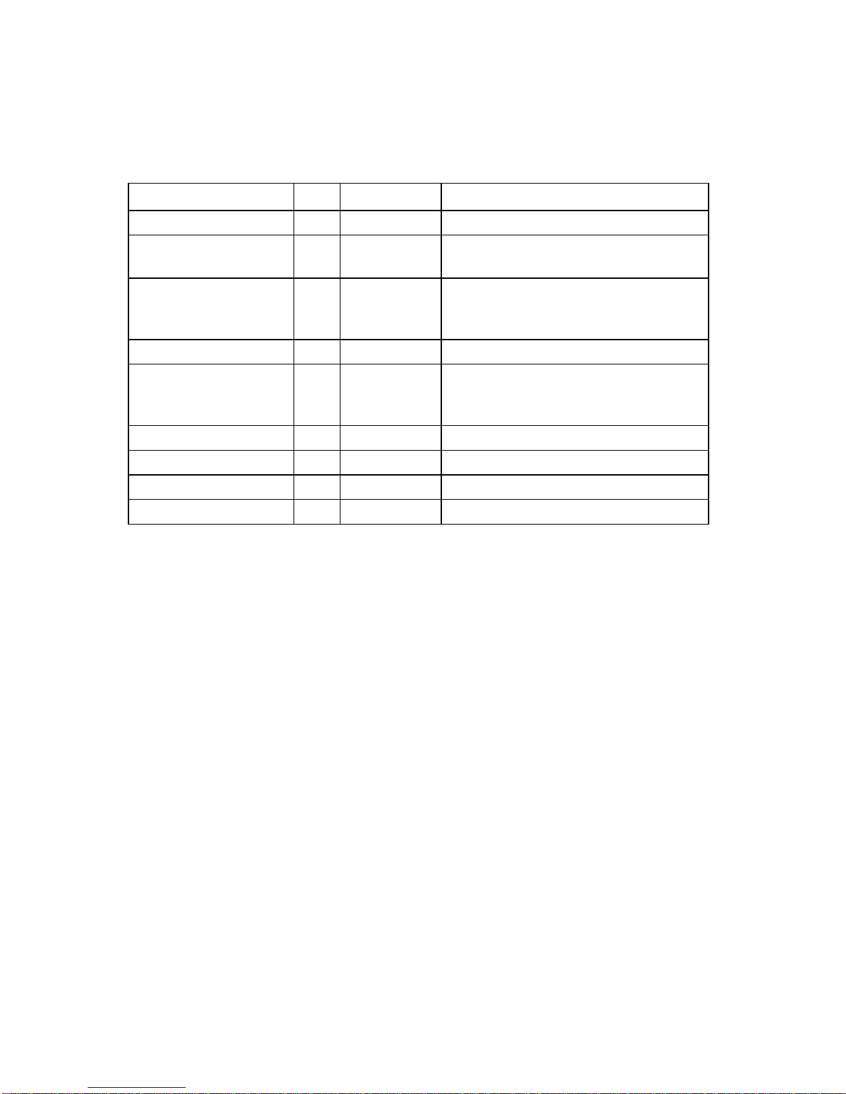
Revision log
Document ID Rev. Date Reason for revision
Man_inst_DPS200_r0 0 2000-02-02 First version
Man_inst_DPS200_r1 1 2000-04-28 New cabinet drawings, added External
Remote Cabinet documentation
Man_inst_DPS200_r2 2 2000-11-17 Output telegrams specified, new
installation specification of coax
connectors, IALA data added.
Man_inst_DPS200_r3 3 2002-02-18 Speed display specification added.
Man_inst_DPS200_r4 4 2003-03-06 RG-214 specifications added, UTM
mode and DGPS 465 description.
Modified 6U and 12U cabinet drawings.
FSP ref.: A11213500XRBRA0

VI
Blank page
FSP ref.: A11213500XRBRA0

VII
Table of contents
1 INTRODUCTION.............................................................................................................1
1.1 About this manual......................................................................................................1
1.2 References..................................................................................................................2
1.3 Abbreviations and acronyms......................................................................................2
2 SPECIFICATIONS...........................................................................................................3
2.1 Physical dimensions...................................................................................................3
2.2 Power .........................................................................................................................3
2.3 Environmental specification ......................................................................................4
2.4 Radio frequencies.......................................................................................................4
2.5 Cable specification.....................................................................................................4
2.6 Compass safe distance ...............................................................................................5
3 INSTALLATION ..............................................................................................................7
3.1 System components....................................................................................................7
3.2 Logistics.....................................................................................................................8
3.3 Location of the system parts.......................................................................................8
3.3.1 DPS 200 unit..................................................................................................8
3.3.2 GPS/GLONASS antenna................................................................................9
3.4 DPS 200 cabinet mounting ........................................................................................9
3.5 Installation of coax connectors.................................................................................10
3.6 Antenna and cable mounting....................................................................................14
3.6.1 GPS/GLONASS antenna and cable mounting.............................................14
3.6.2 IALA beacon antenna and cable mounting ..................................................15
3.7 External inputs and outputs......................................................................................16
3.7.1 Connectors....................................................................................................16
3.7.2 Serial lines....................................................................................................17
3.7.3 PPS signal.....................................................................................................19
3.7.4 Connecting procedure...................................................................................20
3.8 Starting the system...................................................................................................21
3.8.1 Configuring COM ports with RS-232 and RS-422......................................21
3.9 Editing setup file......................................................................................................22
3.9.1 Selecting target.............................................................................................23
3.9.2 Datum...........................................................................................................23
3.9.3 Output telegrams..........................................................................................24
3.9.4 Time and position precision.........................................................................37
3.9.5 Output mode and interval.............................................................................37
3.9.6 UTM mode and zone....................................................................................37
3.9.7 Satellite and fix computation related settings ..............................................38
3.9.8 Height aiding................................................................................................38
3.9.9 Range and age limit on reference stations....................................................39
3.9.10 Differential correction settings.....................................................................39
3.9.11 Handling of corrections (from Fugro Starfix Plus)......................................39
3.9.12 Offsets in reference station co-ordinates......................................................40
FSP ref.: A11213500XRBRA0

VIII
3.9.13 Gyro interface...............................................................................................40
3.9.14 Offset vectors (or lever arms).......................................................................40
3.10 Reference stations ....................................................................................................41
3.11 Commissioning........................................................................................................42
4 INSTALLATION DRAWINGS.....................................................................................43
4.1 Physical description of DPS 6U cabinet ..................................................................44
4.2 Physical description of DPS 12U cabinet ................................................................45
4.3 Block diagram and cable list....................................................................................46
4.4 GPS/GLONASS antenna .........................................................................................47
4.5 GPS/GLONASS antenna mounting specification....................................................48
APPENDIX A - IALA BEACON ANTENNA......................................................................49
APPENDIX B - ½" COAX CABLE SPECIFICATIONS...................................................51
APPENDIX C - RG-213 SPECIFICATIONS......................................................................53
APPENDIX D - DPS SETUP FILE.......................................................................................55
APPENDIX E - REFERENCE STATION DEFAULT FILE.............................................61
APPENDIX F - EXTERNAL REMOTE CABINET...........................................................71
APPENDIX G – MOUNTING WITHOUT DPS 102 CABINET.......................................77
APPENDIX H – NMEA DISPLAY.......................................................................................79
APPENDIX I - OPTIONAL IALA BEACON ANTENNA.................................................85
APPENDIX J – RG-214 SPECIFICATIONS ......................................................................87
APPENDIX K – DGPS 465....................................................................................................89
INDEX .....................................................................................................................................95
READER'S COMMENTS.....................................................................................................97
FSP ref.: A11213500XRBRA0

IX
List of illustrations
Figure 1 Rear view of the DPS 200 unit.................................................................................16
Figure 2 Grounding terminal detail ........................................................................................20
Figure 3 Reconfiguration of comports....................................................................................21
Figure 4 Editing setup file menu ............................................................................................22
Figure 5 Unlock Setup file......................................................................................................22
Figure 6 Setup file editing ......................................................................................................23
Figure 7 External remote cabinet............................................................................................71
Figure 8 Cabinet dimensions..................................................................................................72
Figure 9 Internal assembling...................................................................................................72
Figure 10 Cabling between DPS and remote cabinet.............................................................73
Figure 11 NMEA display........................................................................................................79
Figure 12 NMEA display dimensions ....................................................................................79
Figure 13 Mounting details.....................................................................................................81
Figure 14 Rear panel of the display........................................................................................81
Figure 15 Table of display screens .........................................................................................82
Figure 16 Access and description of sub-screens...................................................................83
Figure 17 MBL-3 Beacon Loop Antenna...............................................................................85
Figure 18 Front view of DGPS 465........................................................................................90
Figure 19 Rear view of DGPS 465.........................................................................................90
Figure 20 Layout DGPS 465/DPS cables...............................................................................90
Figure 21 Starting the UHF channel setting program.............................................................91
Figure 22 Channel setting program ........................................................................................91
List of tables
Table 1 Connectors.................................................................................................................16
Table 2 Configuration of serial lines for DPS 200.................................................................17
Table 3 Pin layout for Com1, Com2 and Com5 to Com10....................................................18
Table 4 Pin layout for MRU port............................................................................................18
Table 5 Pin layout for Aux-Serial Port...................................................................................19
Table 6 ABBDP message fields .............................................................................................25
Table 7 ARABB message fields.............................................................................................25
Table 8 DPGGA message fields.............................................................................................26
Table 9 GGA message fields..................................................................................................27
Table 10 GGA_1.5 message fields.........................................................................................28
Table 11 GGA_MAG message fields.....................................................................................28
Table 12 GGA_CEG message fields......................................................................................29
Table 13 GLL message fields.................................................................................................30
Table 14 GLL_1.5 message fields..........................................................................................30
Table 15 GLL_2.0 message fields..........................................................................................31
Table 16 GNS message fields.................................................................................................31
Table 17 GSA message fields.................................................................................................32
Table 18 GST message fields.................................................................................................33
FSP ref.: A11213500XRBRA0

X
Table 19 GSV message fields.................................................................................................33
Table 20 PSXN_23 message fields.........................................................................................34
Table 21 VBW message fields ...............................................................................................34
Table 22 VTG message fields.................................................................................................35
Table 23 Change between summer and winter time in Westerstrand message.......................35
Table 24 Westerstrand message fields....................................................................................36
Table 25 ZDA message fields.................................................................................................36
Table 26 Example from the ST_COORD_DEF file...............................................................41
Table 27 Example from the ST_COORD.TXT file ...............................................................42
Table 28 Cable terminal strip table.........................................................................................73
Table 29 Serial port and antenna configuration for DGPS 465..............................................89
Table 30 DGPS 465 frequency table......................................................................................92
FSP ref.: A11213500XRBRA0

XI
List of drawings
Drawing no. Title Revision No. of sheets
36200-MA-018 DPS 6U Cabinet Physical Description 2 1
36200-MA-022 DPS 12U Cabinet Physical Description 3 1
36200-GD-006 DPS 200 Block Diagram and Cable List 0 1
36300-MA-017 GPS/GLONASS Antenna Mounting
Specifications 21
Survey AT1675-1 DPS 200/DARPS 200 GPS/GLONASS Antenna 0 1
36200-GD-007 External Remote Cabinet, Block Diagram and
Cable List 01
NA Comrod Beacon Antenna AR 10A/MF 0 1
FSP ref.: A11213500XRBRA0

XII
Blank page
FSP ref.: A11213500XRBRA0

Seatex DPS 200 Installation Manual, rev. 4 Introduction
1
1INTRODUCTION
1.1 About this manual
This manual contains the information necessary to install and set up the DPS 200 equipment
on a vessel. For all other product information, please consult the User’s Manual, reference
[3].
DPS 200 is a very accurate DGPS/DGLONASS positioning sensor. Equipped with two or
more independent DGPS/DGLONASS correction links, increased accuracy and quality
control in the positioning is achieved.
The installation procedures in this manual should be followed in order to achieve the specified
accuracy.
This manual is organised into the following chapters:
Chapter 1 Introduction - A brief presentation of the Installation Manual with references and
abbreviations.
Chapter 2 Specifications - Describes the physical dimensions, required power,
environmental restrictions and cable specifications.
Chapter 3 Installation - Presents procedures to be followed for a typical ship installation
with recommendations on location of the different parts, mechanical and electrical
installation, and how to set up the system.
Chapter 4 Installation Drawings - Contains outline drawings showing the mechanical
dimensions of the different parts in the DPS 200. In addition, it contains a block
diagram including cable list and an antenna mounting drawing.
In this manual the following notations are used:
Is used to make the user aware of procedures and operational practice which, if not
followed, may result in damage to the equipment.
Note A note text has this format and is used to draw the user's attention to special
features or behaviour of the equipment.
CAUTION
FSP ref.: A11213500XRBRA0

Seatex DPS 200 Installation Manual, rev. 4 Introduction
2
1.2 References
[1] NMEA 0183 Standard For Interfacing Marine Electronic Devices, Version 3.0
[2] RTCM Recommended Standards For Differential Navstar GPS service, Version 2.0
[3] DPS 200 User’s Manual, Seatex 2003
[4] DPS 100/102/200 Commissioning Test Procedure, Seatex 2000
[5] Seastar 3100LRS User Manual, Issue 1.0, Fugro Seastar, August 2002
1.3 Abbreviations and acronyms
CTP Commissioning Test Procedure
DGLONASS Differential GLONASS
DGPS Differential GPS
DP Dynamic Positioning System
ECEF Earth Centre Earth Fixed
ED50 European Datum of 1950
EMI Electromagnetic interference
EN European Norm
GLONASS Global Navigation Satellite System
GPS Global Positioning System
IALA International Association of Lighthouse Authorities
LED Light Emitting Diode
NA Not Applicable
NAD27 North American Datum of 1927
NMEA National Marine Electronics Association
PPS Pulse-per-second
RFI Radio frequency interference
RG-213/RG-214 Coax cable used in DPS 200
RTCM Radio Technical Commission for Maritime Service
SCF Supercompressed Format
UPS Uninterruptable power supply used to ensure power supply in case of
mains interruption
UTM Universal Transverse Mercator
WGS84 World Geodetic System of 1984
FSP ref.: A11213500XRBRA0

Seatex DPS 200 Installation Manual, rev. 4 Specification
3
2SPECIFICATIONS
2.1 Physical dimensions
DPS 200 Cabinet
See drawing 36200-MA-018 and 36200-MA-022 on pages 44 and 45 for physical description.
DPS 200 Unit
Width:......................................................................................................482 mm (19-inch rack)
Height:...................................................................................................................132 mm (3 U)
Depth: ..............................................................................................................................430 mm
Weight: ................................................................................................................................12 kg
Colour:.........................................................................................................Front anodised black
GPS/GLONASS Antenna
Height:...............................................................................................................................54 mm
Diameter:.........................................................................................................................243 mm
Net weight: .......................................................................................................................0.96 kg
Voltage input:.................................................................................. 5 V DC from DPS 200 Unit
Colour:................................................................................................................................White
The GPS/GLONASS antenna is a right-hand circular polarised L-band antenna with an
integral low-noise amplifier. The internal thread is5/8- 11 UNC (standard marine mount).
IALA Beacon Antenna
Height:...........................................................................................................................1100 mm
Net weight (including U-bolts):..........................................................................................0.9 kg
The IALA Beacon antenna is a vertically polarised omnidirectional antenna. The antenna can
be mounted on vertical or horizontal mast tubes with 16 to 54 mm in outer diameter.
2.2 Power
Voltage: ................................................................................................................ 110-240 V AC
Power consumption:............................................................................................................75 W
Batteries:.......................................................................None, connection to UPS recommended
FSP ref.: A11213500XRBRA0

Seatex DPS 200 Installation Manual, rev. 4 Specification
4
2.3 Environmental specification
DPS 200 Unit
Enclosure material:.....................................................................................................Aluminium
Enclosure protection:...........................................................................................................IP-53
Operating temperature range: ..................................................................................+5 to +40ºC1
Recommended operating temperature range:..........................................................+20 to +25ºC
Operating humidity:...........................................................................Max. 95% non-condensing
Storage temperature range:...................................................................................... -20 to +60ºC
Storage humidity:...................................................................................................Less than 55%
Vibration testing according to: .....................................................................................EN 60945
GPS/GLONASS Antenna
Enclosure material:..........................................................................................................Polymer
Operating temperature range: .................................................................................. -40 to +65ºC
Operating humidity:................................................................................................... Max. 100%
2.4 Radio frequencies
GPS/GLONASS receiver GG24: ...................................... 1565.42 MHz -1616 MHz (Rx only)
IALA Beacon receiver: ..................................................................280 kHz- 320 kHz (Rx only)
2.5 Cable specification
Coax Cable Specifications (For details see Appendix B)
Type:...................................................................................................1/2" Cellflex superflexible
Attenuation:........................................................................................14 dB/100 m (at 1.5 GHz)
Maximum length: ...............................................................................................................100 m
Diameter:........................................................................................................................13.7 mm
Minimum bend radius:...................................................................................32 mm, single bend
Flame retardation:..............................................IEC 60754-1, -2, IEC 60332-1, -3.C, UL 1581,
....................................................................................................... UL 1666, NEC type CATVR
1Operating temperature up to +55ºC for 10 hours.
FSP ref.: A11213500XRBRA0

Seatex DPS 200 Installation Manual, rev. 4 Specification
5
2.6 Compass safe distance
DPS 200 Unit
Steering magnetic compass: ................................................................................................1.1 m
Standard compass:...............................................................................................................1.9 m
Note If the DPS 200 unit is not marked with a compass safe distance label, the unit
shall be placed seven meters from both the steering compass and the standard
compass.
FSP ref.: A11213500XRBRA0

Seatex DPS 200 Installation Manual, rev. 4 Specification
6
Blank page
FSP ref.: A11213500XRBRA0

Seatex DPS 200 Installation Manual, rev. 4 Installation
7
3INSTALLATION
This chapter covers installation of the DPS 200 unit and the GPS/GLONASS and the IALA
Beacon antennas. A separate installation manual [5] covers Seastar demodulator installation
and connection to the Inmarsat terminal onboard the vessel for reception of
DGPS/DGLONASS correction signals.
The installation includes:
1. Location of the system parts (the DPS 200 unit and the GPS/GLONASS antenna )
2. Mounting of the DPS 200 cabinet
3. Installation of the coax connectors
4. Mounting of the GPS/GLONASS antenna and cable
5. Connecting cables between DPS 200 and external equipment
6. System start
7. Editing setup file
3.1 System components
This chapter describes a typical ship installation of the DPS 200 system. A standard system
delivery consists of:
1. DPS 200 unit
2. Cabinet, 6U
3. Keyboard with rollerball
4. IALA Beacon receiver (included in the DPS 200 unit)
5. GPS/GLONASS antenna
6. DGPS Beacon antenna
7. DPS 200 User's Manual
8. DPS 200 Installation Manual
9. DPS 200 Site Manual
10. Interconnection cable
11. Mains cable
12. Antenna mounting rod
Options:
1. Coax cables for GPS/GLONASS and the IALA Beacon antennas
2. Coax connectors
DPS 200 is supplied in different configurations depending on application and specific user
needs. The DPS 200 cabinet contains the DPS 200 unit and the keyboard with rollerball.
FSP ref.: A11213500XRBRA0

Seatex DPS 200 Installation Manual, rev. 4 Installation
8
In addition to the above supplied parts, the following is needed if external
DGPS/DGLONASS is used:
•Additional cables for input of DGPS/DGLONASS corrections
•Additional cables for output lines to external DGPS/DGLONASS equipment
General Arrangement drawings of the ship should be acquired to simplify GPS/GLONASS
antenna mounting and to estimate sufficient lengths of cable.
For external interfaces, electrical characteristics and data formats must be provided as well as
necessary cables and connectors.
3.2 Logistics
Safety: General safety guidelines should be followed when working in mast and on deck.
Personnel qualifications: Trained electrical workers.
Minimum number of personnel: 2.
Special tools required: None.
3.3 Location of the system parts
Recommended location of the DPS 200 unit and the antenna is described below.
3.3.1 DPS 200 unit
The DPS 200 unit is designed for indoor installation and should not be exposed to heavy
vibrations, electromagnetic fields from transformers or similar.
The unit has internal fans and requires free airflow in front and rear of unit. It is recommended
that ventilation/air conditioning is provided in order to keep the ambient operating
temperature around +20°C. It is also important that the area around the unit is kept free from
dust and static electricity.
All connections to the unit are at the rear side of the cabinet and available space for cable
connections and service must be provided.
Since the keyboard is located in the cabinet, the distance between the monitor and the cabinet
should be limited to a practical range where the monitor may be seen and read from the
position of the cabinet.
FSP ref.: A11213500XRBRA0
Table of contents
Other Seatex Marine GPS System manuals


