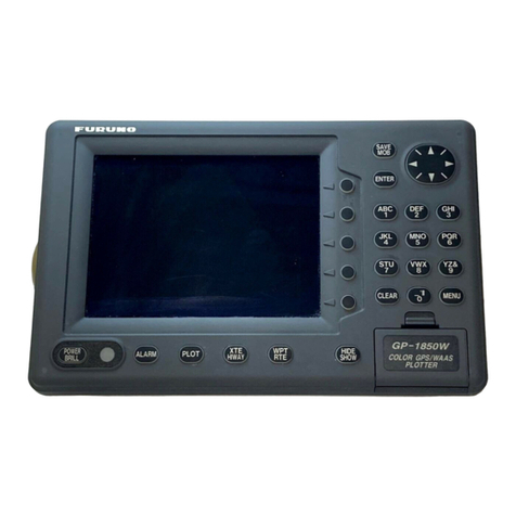
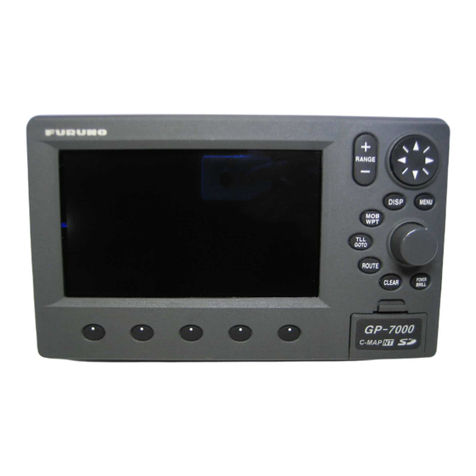
Furuno GP-1610CF User manual


C
9-52, Ashihara-cho,
Nishinomiya, Japan
Telephone: 0798-65-2111
Telefax: 0798-65-4200
Your Local Agent/Dealer
A
ll rights reserved.
PUB. No. OME-43861
GP-1610CF
(
DAMI
)
FIRST EDITION : MAR. 1997
G : MAR. 7, 2001
Printed in Japan

SAFETY INSTRUCTIONS
Safety Instructions for the Operator
Do not disassemble or modify the
equipment.
Fire, electrical shock or serious injury
can result.
Turn off the power immediately if water
leaks into the equipment or the equip-
ment is emitting smoke or fire.
Continued use of the equipment can cause
fire or electrical shock.
Do not place liquid-filled containers on
the top of the equipment.
Fire or electrical shock can result if a
liquid spills into the equipment.
Do not operate the equipment with wet
hands.
Electrical shock can result.
Keep heater away from equipment.
Heat can alter equipment shape and melt
the power cord, which can cause fire or
electrical shock.
Do not open the equipment.
Hazardous voltage which can
cause electrical shock, burn or
serious injury exists inside the
equipment. Only qualified
personnel should work inside
the equipment.
WARNING
Use the proper fuse.
Use of a wrong fuse can result in fire or
permanent equipment damage.
GPS position and velocity accuracies
are controlled by the U.S. Department
of Defense. Position may be degraded
up to 100 meters.
Do not use the equipment for other than
its intended purpose.
Personal injury can result if the equipment
is used as a chair or stepping stool, for
example.
Do not place objects on the top of the
equipment.
The equipment can overheat or personal
injury can result if the object falls.
CAUTION
The TFT LCD is constructed using the
latest LCD techniques, and displays
99.99% of its pixels. The remaining 0.01%
of the pixels may drop out or blink, how-
ever this is not an indication of malfunc-
tion.
About the TFT LCD

Safety Instructions for the Installer
Do not work inside the
equipment unless totally
familiar with electrical
circuits.
Hazardous voltage which can
shock, burn or cause serious
injury exists inside the equip-
ment.
Turn off the power at the
mains switchboard before
beginning the installation.
Post a sign near the switch
to indicate it should not be
turned on while the equip-
ment is being installed.
Fire, electrical shock or
serious injury can result if the
power is left on or is applied
while the equipment is being
installed.
WARNING
Ground the equipment to
prevent electrical shock
and mutual interference.
Confirm that the power supply voltage
is compatible with the voltage rating
of the equipment.
Connection to the wrong power supply
can cause fire or equipment damage. The
voltage rating appears on the label at the
rear of the display unit.
Use the correct fuse.
Use of a wrong fuse can cause fire or
equipment damage.
Keep the following compass safe
distance.
Standard Steering
Display Unit 0.7 m 0.6 m
CAUTION

i
FOREWORD
A Word to GP-1610CF Owners.................iv
Features.......................................................v
System Configuration................................vi
INSTALLATION
1.1 Equipment Lists............................. 1-1
1.2 Installation of Standard
Equipment ..................................... 1-3
1.3 Installation of Transducers .......... 1-10
1.4 Installation of Optional
Sensors ........................................ 1-19
1.5 Connection of Optional
Equipment ................................... 1-21
1.6 Initial Settings ............................. 1-24
OPERATIONAL OVERVIEW
2.1 Control Description ....................... 2-1
2.2 Inserting Chart Cards .................... 2-2
2.3 Turning On/Off the Power............. 2-2
2.4 Adjusting Tone and Brilliance....... 2-3
2.5 Plotter Displays ............................. 2-3
2.6 Sounder Displays........................... 2-5
2.7 Basic Menu Operation................... 2-7
VIDEO SOUNDER OPERATION
3.1 Principle of Operation ................... 3-1
3.2 Automatic Sounder Operation....... 3-2
3.3 Manual Sounder Operation ........... 3-2
3.4 Suppressing Low Level Noise....... 3-3
3.5 Selecting Picture Advance
Speed ............................................. 3-4
3.6 Suppressing Interference ............... 3-4
3.7 Erasing Weak Echoes .................... 3-4
3.8 Changing Zoom Magnification
Factor............................................. 3-5
3.9 Selecting Hue
(color arrangement) ....................... 3-5
3.10 Measuring Depth ........................... 3-5
3.11 Knowing Depth Change by
Audible Chime .............................. 3-5
3.12 Selecting Unit of Depth
Measurement ................................. 3-6
3.13 Offsetting the Depth Readout........ 3-6
TABLE OF CONTENTS BY SUBJECT
3.14 Displaying the Water Temperature
Graph............................................. 3-6
3.15 Selecting Unit of Water
Temperature Measurement ............ 3-7
3.16 Offsetting Water Temperature
Readout.......................................... 3-7
3.17 Fish Alarm ..................................... 3-7
3.18 Bottom Alarm ................................ 3-8
3.19 Water Temperature Alarm ............. 3-8
3.20 Turning On/Off the Expansion
Range Marker ................................ 3-8
3.21 Receiver Sensitivity (gain)
Adjustment .................................... 3-9
3.22 Selecting Bottom-Lock
Expansion Width ........................... 3-9
3.23 Stopping Transmission .................. 3-9
3.24 Interpreting the Display............... 3-10
GPS, CHART OVERVIEW
4.1 Principle of GPS............................ 4-1
4.2 Presentation Mode......................... 4-3
4.3 Shifting the Cursor ........................ 4-3
4.4 Selecting Screen Center by
Cursor ............................................ 4-4
4.5 Shifting the Display....................... 4-4
4.6 Centering Position ......................... 4-4
4.7 Changing Chart Scale/Range ........ 4-4
4.8 Chart Cards.................................... 4-4
TRACK
5.1 Stopping/Restarting Plotting of
Track.............................................. 5-1
5.2 Changing Track Color ................... 5-1
5.3 Erasing All Track........................... 5-1
5.4 Changing Track Plotting
Interval .......................................... 5-2
5.5 Smoothing Track ........................... 5-2
MARKS
6.1 Entering Marks .............................. 6-1
6.2 Entering Event Marks.................... 6-1
6.3 Erasing Individual Marks .............. 6-2
6.4 Changing Mark Attributes............. 6-2
6.5 Entering the MOB Mark ............... 6-3
6.6 Erasing All Marks.......................... 6-3
6.7 Radar Target Mark......................... 6-4
ii
WAYPOINTS, ROUTES
7.1 Entering Waypoints ....................... 7-1
7.2 Erasing Individual Waypoints ....... 7-3
7.3 Changing Waypoint Position......... 7-3
7.4 Changing Waypoint Mark Size ..... 7-4
7.5 Entering Routes ............................. 7-4
7.6 Editing Routes ............................... 7-5
7.7 Erasing Routes............................... 7-5
SETTING DESTINATION
8.1 Setting Destination ........................ 8-1
8.2 Skipping Route Waypoints ............ 8-3
8.3 Cancelling Destination .................. 8-3
PLOTTER-RELATED ALARMS
9.1 Arrival/Anchor Watch Alarm ........ 9-1
9.2 XTE (Cross Track Error) Alarm.... 9-2
9.3 Speed Alarm .................................. 9-2
9.4 Trip Alarm ..................................... 9-2
POSITION-RELATED
OPERATIONS
10.1 Displaying Position in LOPs ....... 10-1
10.2 Offsetting GPS Position .............. 10-1
10.3 Selecting Navaid ......................... 10-2
10.4 Displaying True or Magnetic
Bearings....................................... 10-2
10.5 Magnetic Variation ...................... 10-2
10.6 Offsetting Chart Position............. 10-3
GPS OPERATIONS
11.1 GPS Setup Menu ..........................11-1
11.2 Speed Averaging...........................11-2
OPTIONAL EQUIPMENT
SETUP
12.1 Selecting Sensors......................... 12-1
12.2 Selecting Autopilot, Remote
Display ........................................ 12-1
12.3 Setting up DGPS Beacon
Receiver....................................... 12-1
CUSTOMIZING THE DISPLAY
13.1 Plotter Display Marker
Attributes..................................... 13-1
13.2 Chart Attributes ........................... 13-1
13.3 Unit of Distance Measurement.... 13-2
13.4 Chart Range or Scale Indication.. 13-2
MAINTENANCE &
TROUBLESHOOTING
14.1 Maintenance ................................ 14-1
14.2 Replacement of Fuse, Battery ..... 14-1
14.3 Simple Troubleshooting .............. 14-2
14.4 Error Messages............................ 14-3
14.5 Diagnostic Tests .......................... 14-4
14.6 GPS Monitor Display .................. 14-5
14.7 Demonstration Display................ 14-6
14.8 Memory Card Operations
(for technicians)........................... 14-6
14.9 Clearing the Memory .................. 14-7
APPENDIX
Specifications..........................................A-1
World Time Standards ............................A-2
Geodetic Chart List.................................A-3
Icons .......................................................A-4
Glossary ..................................................A-5
Menu Tree...............................................A-9
Decca Chains ........................................A-12
Packing List ..........................................A-13
DRAWINGS
Antenna Unit...........................................D-1
Display Unit............................................D-2
SCHEMATIC DIAGRAMS
GPS Plotter Interconnection Diagram .... S-1
GPS Plotter Schematic Diagram............. S-2
GPS Plotter Schematic Diagram............. S-3
INDEX

iii
TABLE OF CONTENTS BY DISPLAY ITEM
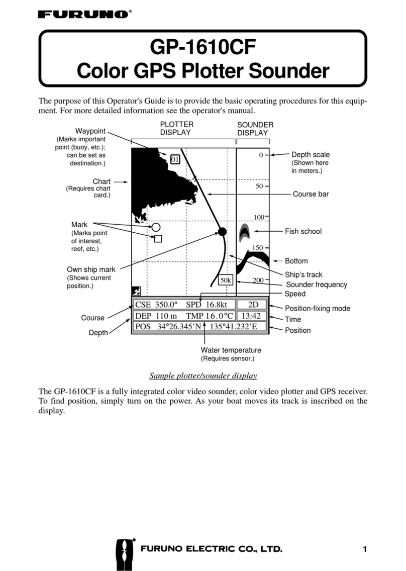
Course bar (Page 13-1)
01
PLOTTER
DISPLAY (Page 2-3)
SOUNDER
DISPLAY
(Page 2-5)
Fish school (Page 3-10)
Bottom (Page 3-10)
Position-fixing mode (Page 2-2)
Time (Page 11-2)
Position (Page 4-2)
CSE 350.0°SPD 16.8kt 2D
DEP 110 m
TMP 16.0°C 13:42
POS 34°26.345’N 135°41.232’E
50k
0
50
100
150
200 Sounder frequency (Page 2-5)
BRG+ 232.0°RNG+ 0.00nm 2D
DEP 110 m
TMP 16.0°C 13:42
+ 34°43.801’N 135°21.163’E
Track (Page 5-1)
Own ship mark (Page 5-1)
Course to destination (Page 8-1)
Flag (destination) (Page 8-1)
Arrival alarm range (Page 9-2)
Waypoint
(Page 7-1)
Grid (Page 13-1)
Marks (Page 6-1)
Cross-track error
alarm range
(Page 9-2)
Icons (Page A-4)
CURS key alternates
these displays.
Cursor position
in latitude and
longitude (Page 4-3)
LL
H
Chart (Page 4-4)

iv
FOREWORD
A Word to GP-1610CF Owners
Congratulations on your choice of the FURUNO GP-1610CF
COLOR GPS PLOTTER SOUNDER. We are confident you will
see why the FURUNO name has become synonymous with qual-
ity and reliability.
For over 40 years FURUNO Electric Company has enjoyed an
enviable reputation for innovative and dependable marine elec-
tronics equipment. This dedication to excellence is furthered by
our extensive global network of agents and dealers.
This equipment is designed and constructed to meet the rigorous
demands of the marine environment. However, no machine can
perform its intended function unless installed, operated and main-
tained properly. Please carefully read and follow the recommended
procedures for installation, operation and maintenance.
We would appreciate hearing from you, the end-user,aboutwhether
we are achieving our purposes.
Thank you for considering and purchasing FURUNO equipment.

v
Features
The GP-1610CF is a totally integrated GPS receiver, color video
plotter and color video sounder. It mainly consists of a display unit
and a GPS antenna.
Navigation information is displayed on a bright 5.6-inch color TFT
LCD. On-screen information shown are position, range and bear-
ing to cursor position, range, bearing, ETA and TTG to waypoint,
etc.
A high sensitivity receiver tracks up to eight satellites simulta-
neously. An 8-state Kalman filter ensures optimum accuracy in
determination of vessel position, course and speed.
The main features of the GP-1610CF are
• Comprehensive navigation data displays.
• Bright 5.6-inch color LCD with temperature compensated tone
and brilliance control.
• Automatic coastline chart loading.
• Position display in latitude and longitude, Loran C LOPs or
Decca LOPs.
• Outputs steering information to FURUNO autopilots (FAP-50/
55/300/330).
• Improved position accuracy with connection of DGPS beacon
receiver (option).
• FURUNO and NAVIONICS chart cards.
• Memory capacity: 2,000 points of track, 100 marks, 100 event
marks, 200 waypoints and 20 routes.
• Alarms:Arrival,Anchor Watch, Cross-track Error, Depth, Fish,
Speed, Trip, and Water Temperature.
• Man overboard feature records latitude and longitude coordi-
nates at time of man overboard and provides continuous up-
dates of range and bearing to that point.
• "Highway" display provides graphic presentation of ship's track
and is useful for monitoring cross track error.
• Automatic or manual video sounder operation.

vi
System Configuration
The GP-1610CF mainly consists of a display unit and a GPS an-
tenna.Adualfrequency transducer is optionally available.The chart
carddriveinthe display unit loads electronic charts. External equip-
ment which can be connected include water temperature and speed
sensors, autopilot, and DGPS beacon receiver.
Ship’s mains
10.2—31.2 VD
C
External equipment
(Autopilot, etc.)
DGPS beacon receiver
(option)
Transducer
(option)
Temp. sensor
(option)
ANTENNA UNIT
Receives signal from
GPS satellite.
DISPLAY UNIT
Ship’s position is
calculated in longitude
and latitude from signal
received from the an-
tenna unit and displayed
on the screen.

1-1
INSTALLATION
1.1 Equipment Lists
Standard supply
.oNemaNepyT.oNedoCytQskrameR
1tinUyalpsiD E-FC0161-PG 1
2tinUannetnA 610-APG 1
3
noitallatsnI
slairetaM 00300-68PC830-140-000tes1
4straPerapS 00300-68PS 046-493-400tes1
Optional equipment
.oNemaNepyT.oNedoCskrameR
1
annetnA
teselbac
00710-02PC011-273-400
rof,m03
elbacannetna
noisnetxe
01710-02PC021-273-400
rof,m05
elbacannetna
noisnetxe
2
elgna-thgiR
esabannetna
033AQ-31.oN932-308-000
gnitnuomroF
tinuannetna
3
elgna-L
esabannetna
013AQ-31.oN042-308-000
4
esabannetnA
liarrof
gnitnuom
0615CR-31.oN411-608-000
5
tnuomtsaM
erutxif
11110-02PC227-040-000
6rosnesTS BSM20-TS689-731-000epytlluh-urhT
BSP20-TS789-731-000
7
erutarepmeT
rosnes
BTM20-T620-040-000
,elbacm8htiW
tnuommosnart
BSM30-T720-040-000
,elbacm8htiW
epytlluh-urht

1-2
Optional equipment (con't)
.oNemaNepyT.oNedoCskrameR
8recudsnarT
DSP5-025 521-510-000
DWP5-025621-510-000
m8htiW
mosnart,elbac
tnuom
DSM5-025721-510-000
elbacm8htiW
foorpretawdna
rotcennoc
9
lauD
ycneuqerf
recudsnart
DSM-TS425422-510-000
DWP-TS025821-510-000
01.yssaelbaC
001-1100FPS6A-JM633-231-000
m01,P4-P6
050-1100FPS6A-JM442-231-000
m5,P4-P6
001-2100FPS6A-JM718-331-000
m01,P6-P6
050-2100FPS6A-JM424-431-000
m5,P6-P6
050-3000FPS7A-JM10-037-631-000
m5,P6-P7
SPGDrof
11
lluhrennI
Stik
0-1910S22895-208-000
21
retrevnoC
tesrotcennoc
01300-68PC082-593-400

1-3
1.2 Installation of Standard Equipment
Installing the display unit
Mounting considerations
The display unit can be installed on a tabletop or on the overhead.
When selecting a mounting location for the display unit keep the
following in mind:
• Keep the display unit out of direct sunlight.
• The temperature and humidity should be moderate and stable.
• Locate the unit away from exhaust pipes and vents.
• The mounting location should be well ventilated.
• Mount the unit where shock and vibration are minimal.
• Keep the unit away electromagnetic field generating equipment
such as motor, generator.
• For maintenance and checking purposes, leave sufficient space
at the sides and rear of the unit and leave slack in cables.
• A gyrocompass will be affected if placed too close to the dis-
play unit. Observe the following compass safe distances to pre-
vent disturbance to the gyrocompass:
Standard compass: 0.7 meters
Steering compass: 0.6 meters
Cover
Tabletop Overhead
Figure 1-1 Display unit mounting methods

1-4
Tabletop mounting
Figure 1-2 Display unit mounting methods
Installing the antenna unit
Mounting considerations
When selecting a mounting location for the antenna unit, keep in
mind the following points:
• Select a location out of the radar beam. The radar beam will
obstruct or prevent reception of the GPS satellite signal.
• Be sure the location offers a clean line-of-sight to satellite. Ob-
jects within line-of-sight to a satellite, for example, a mast or
funnel, block reception and cause prolonged acquiring time or
interruption of position fix.
• Mount the unit as high as possible. This will keep the unit free
of water spray, which can interrupt reception of GPS satellite
signal if frozen.
• Separate the unit well away from the antenna of radio equip-
ment.
Dumm
y
cover
Cutting size for flushmount

1-5
Figure 1-3 Typical antenna unit mounting locations
Antenna unit mounting procedure
You will need a medium size slotted-head screwdriver and vinyl
tape.
The standard antenna is usually fastened to a length of pipe and
fastened to a mast. (A mast mount fixture is optionally available
for this.) The threaded antenna base accepts a standard antenna
mount with a 1"-14 straight thread. Mount the antenna on a length
of pipe with a 1"-14 threaded end.
1. Pass the antenna cable through the pipe. Fasten the connector
on the cable to the antenna.
Antenna
Pipe
Antenna cable
Figure 1-4 Passing antenna cable through pipe

1-6
2. Screw the pipe into the antenna. DO NOT USE TOOLS TO
FASTEN THE ANTENNA TO ITS MOUNTING; ONLY
HAND TIGHTEN.
Pipe
Figure 1-5 Fastening pipe to antenna
3. Tape the junction between the pipe and antenna unit with vinyl
tape.
Taping
Figure 1-6 Taping the antenna
4. Attach the mounting fixture to the mast and set the pipe with
antenna to the mounting fixture.
Mounting
fixture (note direction)
Mast
Figure 1-7 Attaching antenna to mounting fixture

1-7
5. Tape the antenna unit, mounting fixture and mast with vinyl
tape.
Vinyl tape
Figure 1-8 Securing antenna to mast with vinyl tape
6. Attach a clamp to the antenna unit and tighten. Leaving some
slack in the antenna cable as shown, fix it with vinyl tape.
Slotted-head
screwdriver
Clamp
Vinyl tape
Leave slack
in cable.
Figure 1-9 Fixing the antenna cable with vinyl tape

1-8
Wiring
All wiring are terminated at the rear of the display unit.
Power cable
Connect the power cable to the power connector. Connect the leads
to the battery (12 or 24 VDC); white to plus(+) terminal and black
to minus(-) terminal.
Cable connector
Power cable
w/fuse (3A)
Lead wire
White
Black
BATTERY
Figure 1-10 Connecting the power cable to the battery
Antenna unit
Connect the antenna unit cable to the GPS ANT connector.
Transducer
Connect the transducer cable to the XDR connector.
Ground
The display unit
contains several
CPUs. While they
are operating, they
radiate noise,
whichcan interfere
with radio equip-
ment. Ground the
unit to prevent interference. The grounding wire should be 1.25 sq
or larger and as short as possible. Connect the grounding wire to
ship's ground by silver-alloy brazing. On a fiberglass boat, it is
best to install a ground plate that measures about 20 cm by 30 cm
on the outside of the hull bottom to provide a ground point. If this
is not practical, the engine block can be used.
Ground the equipment to
prevent electrical shock
and mutual interference.
CAUTION

1-9
Earth terminal
ANTENNA UNIT
DISPLAY UNIT
Ext.
equip.
DPGS beacon receiver
Black White
Shield
TRANSDUCER
Earth
Figure 1-11 Display unit, rear view

1-10
1.3 Installation of Transducers
Installing the inside-hull mount transducer
Necessary tools
You will need the following tools:
• Sandpaper (#100)
• Silicone sealant
• Silicone grease
Remarks on installation
• Do the installation with the boat hauled out of the water.
• Turn off the engine while installing the equipment.
• Install the transducer in the engine room.
Selecting the mounting location
Keep the following points in mind when selecting a mounting lo-
cation:
• The mounting location should be where the hull is of single-
hull thickness and is void of air or flotation materials other than
solid fiberglass between the transducer face and the water.
• Do not place the transducer over hull struts or ribes which run
under the hull.
• Avoid a location where the rising angle of the hull exceeds 15°,
to minimize the effect of the boat’s rolling.
• You will finalize the mounting location through some trial and
error. The procedure for this is shown later.
50cm
50cm
15cm
15cm
1/3
1/2
Mounting location
for transducer
Center line
Figure 1-12 Inside-hull transducer mounting location
Other manuals for GP-1610CF
1
Table of contents
Other Furuno Marine GPS System manuals

Furuno
Furuno GP-1650W User manual

Furuno
Furuno Navpilot 500 User manual

Furuno
Furuno GP-1850DF Manual

Furuno
Furuno NAVpilot-500 User manual

Furuno
Furuno GP-7000 Manual

Furuno
Furuno GP-7000F User manual

Furuno
Furuno GP-3500F-D User manual

Furuno
Furuno 1834C Manual

Furuno
Furuno GP-1650W User manual

Furuno
Furuno GD-1700C User manual

Furuno
Furuno GP-1800 User manual

Furuno
Furuno GP-3500F User manual

Furuno
Furuno GP-7000F User manual

Furuno
Furuno GP-1800F User manual

Furuno
Furuno FELCOM 12 User manual

Furuno
Furuno GP-1810F User manual

Furuno
Furuno SC-33 User manual

Furuno
Furuno FELCOM 250 User manual

Furuno
Furuno GP-70 Mark-2 Manual

Furuno
Furuno SC-30 Owner's manual