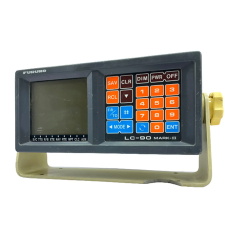
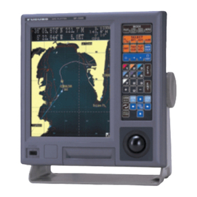
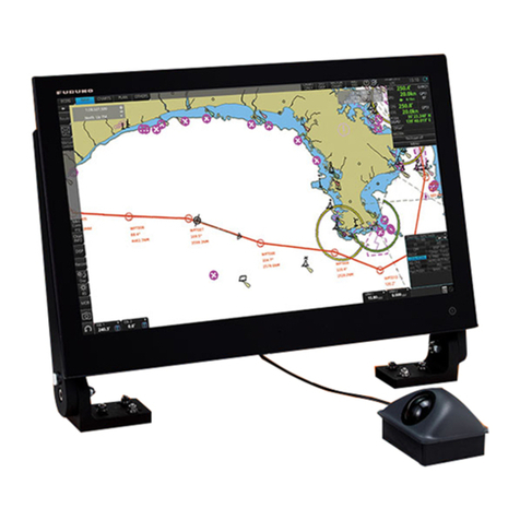
Furuno GP-150 User manual

3.46
8.4
POSITION
WGS84
RNG
SOG COG
BRG
nm
kt
206.
34 44
135 21
216
6
4
N
COG
BRG
nm
kt
206.1
34 44.449' N
135 21.219' E
216
6.1
34 44.449' N
135 21.219' E
216
84
SOG COG
BRG
kt
206 1
34 44.4
135 21.2
216
Catalogue No. N-000
R
R
TRADE MARK REGISTERED
MARCA REGISTRADA
The future today with FURUNO's electronics technology.
FURUNO ELECTRIC CO., LTD.
9-52 Ashihara-cho, Nishinomiya City, Japan Phone: +81 (0)798 65-2111
Fax: +81 (0)798 65-4200, 66-4622 URL: www.furuno.co.jp
FURUNO DEEPSEA WORLD
Global Positioning System
Marine GPS Navigator
GP-150

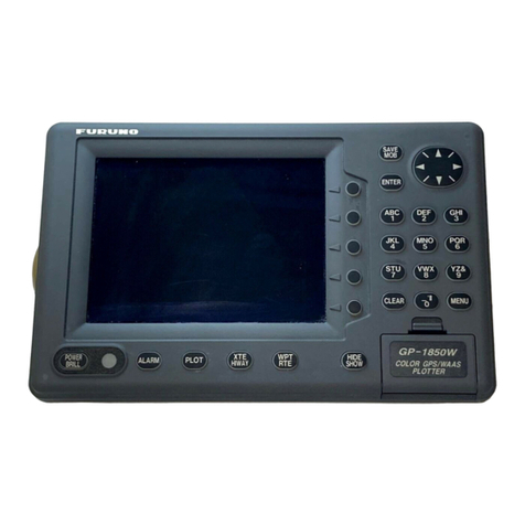
The GP-150 consists of an antenna and display unit.
The display unit is a 6" silver bright LCD,
offering optimum viewing around the clock.
In order to improve position accuracy, WAAS
and DGPS* augmentation systems are
available.Dual configuration, with a second
system, provides a backup and/or
remote operation to ensure system
availability.
*Internal or external beacon receiver is required for
utilizing DGPS.
Global Positioning System
An outstanding solution
standalone positioning d
DGPS Antenna:
GPS/WAAS Antenna:
GPA-019S
GPA-018S
GPA-017S
GP-150
MARINE GPS NAVIGATOR
Display Unit
FURUNO GP-150 is a GPS navigator designed for the SOLAS ships according to the GPS
performance standard IMO Res MSC.112(73) and associated IEC standards effective on and
after July 1, 2003. It is a highly reliable standalone EPFS (electronic position fixing system)
that feeds positioning information to AIS, Radar, VDR, VideoPlotter, Autopilot, Echo Sounder
and Sonar.
Receiver dependability is improved by fault detection using five satellites, i.e., Receiver
Autonomous Integrity Monitoring (RAIM) that shows the integrity status in Safe, Caution, and
Unsafe levels. The status is given with respect to user selected accuracy level, 10 m or 100 m.
RAIM also works on DGPS signals.

n for SOLAS carriage requirements as a
device and as a sensor for AIS, Radar, VDR, etc.
sFully meets new IMO Resolution MSC.112(73) and IEC 61108-1 Ed.2 for SOLAS carriage
requirements on and after 1 July 2003
sIdeal sensor of SOG and COG for AIS, radars, and other navigational aids
sAugmentation to enhance accuracy by standard fitted WAAS
and optional DGPS
sDisplay modes: VideoPlotter, 3-D Highway,
Text, Steering.
sMemory: 2,000 points for ship's past positions
and marks (incl. 99 event marks max.);
999 waypoints; 30 routes
each containing up to 30
waypoints
Display mode is selectable from VideoPlotter, Text,
Highway and Steering. In the Highway mode, you can
intuitively see how to steer and where the next
waypoint is located relative to your ship. It is useful
when you are following a series of waypoints along a
planned route.
Highway mode
Steering mode
VideoPlotter mode
Text mode
The SOLAS Chapter V
as amended in
December 2000 prohibits
new installation of current
GPS receivers which are
disigned to IMO A.819
after 1 July 2003*. With
the comparison table,
you will see why we say
the new IMO equipment
is epoch making.
* Some Administrations may give a grace period for the current GPS receivers.
MSC.112(73), IEC 61108-1 ed.2 A.819(19), IEC 61108-1 ed.1
Accuracy 13 m (95%) 100 m (95%)
SOG (speed over ground) Required to accuracy of SDME SOG prohibited, no testing standard
COG (course over ground) Required to accuracy of
+1 ( 17 kt),
+3 ( 17 kt) COG prohibited, no testing standard
UTC Required to output Data is limited to only L/L
RAIM (Receiver autonomous
integrity monitoring)
Required to indicate integrity indication
of Safe, Caution, Unsafe at confidence
level of 10 m and 100 m
No
Display update rate 1 s at latest every 2 s

6
4
N
6
1
2
GP-150
Option and Connectable Equipment
Standard System Configuration
External Buzzer
Rectifier PR-62
12-24 VDC115/230 VAC
Antenna Unit
3 m
15 m (30/50 m)
Radar
DGPS Antenna Unit
GPA-019SGPA-018S
5 m (10 m)
DGPS Beacon Receiver
Second Display
Rectifier PR-62
12-24 VDC 115/230 VAC
12/24 VDC
3 m
15 m (30/50 m)
1J
DGPS Antenna Unit
GPA-019SGPA-018S
2J 3J
4J~8J 10J~12J
GPA-017S
Antenna Unit
GPA-017S
AIS
Sonar
Echo Sounder
Autopilot
VideoPlotter
Radar
AIS
Sonar
Echo Sounder
Autopilot
VideoPlotter
PC
IF-2500
Interface Unit
External Alarm System
TRADE MARK REGISTERED MARCA REGISTRADA
SPECIFICATIONS SUBJECT TO CHANGE WITHOUT NOTICE
05113N Pri0nted in Japan
EQUIPMENT LIST
Standard
1. Display Unit (Specify single or dual) 1 unit
2. Antenna Unit GPA-017S
GPA-018S*
GPA-019S* 1 unit
(specify when ordering)
*Selectable when a beacon receiver is incorporated into a display unit.
3. Antenna Cable 15 m
4. Interface Cable 5 m x 2 pcs
5. Installation Materials and Spare Parts 1 set
Option
1. DGPS Receiver Kit OP20-32-1/20-33
2. Whip Antenna FAW-1.2 for GPA-018S
3. Antenna Cable, 30/50 m
4. Interface Cable, 5/10 m
5. Antenna Base
CP20-01111 (Pipe mount), No.13-QA330 (Deck mount)
No.13-QA310 (Offset bracket), No.13-RC5160 (Handrail
mount)
6. Flush Mount Kit OP20-24/20-25
7. Interface Unit IF-2500
8. External DGPS Receiver GR-80
9. Rectifier PR-62
SPECIFICATIONS
GPS
Receiver 12 discrete channels all-in-view, C/A code
RX Frequency L1 (1575.42 MHz)
Time to First Fix 12 s (Warm start)
Tracking Velocity 900 kt
Geodetic System WGS-84 (NAD-27 or others selectable)
Update Rate 1 s
Positioning Augmentation
DGPS
Reference Station: Automatic or manual selection
Frequency Range: 283.5 - 325.0 kHz (all ITU regions)
Format: RTCM SC-104 Ver 2.0 Type1, 7, 9, 16
WAAS
WAAS augmentation is available through the GPS core in the display
unit
Accuracy GPS: 10 m (95%)
DGPS: 5 m (95%)
WAAS: 3 m (95%), limited coverage
SOG: ±0.2 kt (SOG ≦10 kt)
COG: ±3° (SOG 1-17 kt), ±1° (SOG > 17 kt)
Display 6" LCD (120 x 91 mm),
320 (H) x 240 (V) pixels,
L/L resolution: 0.001 min
Display Modes VideoPlotter, Highway, Text, Steering
VideoPlotter Scale: 0.02 to 320.0 nm,
Plot Interval: 1 s - 60 min or 0.01-99.99 nm
Memory Capacity
2,000 points for ship's track and marks, 999 waypoints with comments,
30 routes (containing 30 waypoints/route)
Alarms
Arrival, anchor watch, XTE, Speed, Time, Water Depth, Trip, DGPS,
WAAS
Integrity indication
Safe, Caution, Unsafe at accuracy level of 10 m or 100 m
Interface (IEC 61162-1 Ed 2, NMEA 0183)
Output GBS (satellite fault), GLL (L/L), VTG (SOG, COG),
ZDA(UTC), WPL (WPT location), etc.
Input DBT (Depth), HDT (Compass), MTW (Water temperature),
TLL (TGT L/L), VBW (Dual grd/wat spd), etc.
ENVIRONMENT (IEC 60945 test method)
Temperature Display Unit: -15°C to +55°C
Antenna Unit: -25°C to +70°C
Waterproofing Display Unit: IPX5 (IEC 60529)
Antenna Unit: IPX6 (IEC 60529)
EMC IEC 60945 Ed. 4 (up to 2 GHz)
POWER SUPPLY
12-24 VDC, 0.8-0.4 A
160 6.3"
80 3.1"
112 4.4"
290 11.4"
250 9.8"
260 10.2"
180 7.1"
4 - 6
Display Unit
Antenna Unit
0.15 kg 0.3 lb
2.2 kg 4.9 lb
24 0.9"61 2.4"
32 1.3"
69 2.7"
40 1.5"
126 4.9"
110 4.3"
116 4.6"
156 6.1"
GPA-017S
0.3 kg 0.7 lb
GPA-018S
1.0 kg 2.2 lb
GPA-019S
Interconnection Diagram
FURUNO U.S.A., INC.
Camas, Washington, U.S.A.
Phone: +1 360-834-9300
Fax: +1 360-834-9400
FURUNO (UK) LIMITED
Denmead, Hampshire, U.K.
Phone: +44 2392-230303
Fax: +44 2392-230101
FURUNO FRANCE S.A.
Bordeaux-Mérignac, France
Phone: +33 5 56 13 48 00
Fax: +33 5 56 13 48 01
FURUNO ESPAÑA S.A.
Madrid, Spain
Phone: +34 91-725-90-88
Fax: +34 91-725-98-97
FURUNO DANMARK AS
Hvidovre, Denmark
Phone: +45 36 77 45 00
Fax: +45 36 77 45 01
FURUNO NORGE A/S
Ålesund, Norway
Phone: +47 70 102950
Fax: +47 70 127021
FURUNO SVERIGE AB
Västra Frölunda, Sweden
Phone: +46 31-7098940
Fax: +46 31-497093
FURUNO FINLAND OY
Espoo, Finland
Phone: +358 9 4355 670
Fax: +358 9 4355 6710
FURUNO POLSKA
Sp. Z o.o.
Gdynia, Poland
Phone: +48 58 669 02 20
Fax: +48 58 669 02 21
FURUNO
DEUTSCHLAND GmbH
Rellingen, Germany
Phone: +49 4101 838 0
Fax: +49 4101 838 111
LLC FURUNO EURUS
Petersburg, Russia
Phone: +7 812 767 15 92
Fax: +7 812 766 55 52

INSTALLATION MANUAL
GPS NAVIGATOR
GP-150
1. SYSTEM CONFIGURATIONS ..........................................................................1
2. EQUIPMENT LIST............................................................................................2
3. DISPLAY UNIT..................................................................................................4
4. ANTENNA UNIT................................................................................................6
5. WIRING ...........................................................................................................10
6. INITIAL SETTINGS.........................................................................................12
7. OPTIONAL DGPS...........................................................................................23
PACKING LISTS & INSTALLATION MATERIALS........................................... A-1
OUTLINE DRAWINGS...................................................................................... D-1
INTERCONNECTION DIAGRAM ......................................................................S-1


SAFETY INSTRUCTIONS
WARNING
Do not work inside the
equipment unless totally
familiar with electrical
circuits.
Hazardous voltage which can
cause electrical shock, burn
or serious injury exists inside
the equipment.
Turn off the power at the
mains switchboard before
beginning the installation.
Post a sign near the switch
to indicate it should not be
turned on while the equip-
ment is being installed.
Fire, electrical shock or
serious injury can result if the
power is left on or is applied
while the equipment is being
installed.
Ground the display unit to
prevent loss of sensitivity
and mutual interference.
Confirm that the power supply voltage
is compatible with the voltage rating
of the equipment.
Connection to the wrong power supply
can cause fire or equipment damage. The
voltage rating appears on the label at the
rear of the display unit.
Use the correct fuse.
Use of a wrong fuse can cause fire or
equipment damage.
Keep the following compass safe
distances:
Standard Steering
Display unit 0.50 m 0.35 m
CAUTION

This page is intentionally left blank.

1
1. SYSTEM CONFIGURATIONS
Antenna Unit GPA-018S*
Display Unit
Radar, Echosounder,
Autopilot etc.
DGPS Beacon
Receiver
GR-80**
12-24VDC
Antenna Unit GPA-017S**
Antenna Unit GPA-019S*
*: w/internal beacon receiver
**: w/o internal beacon receiver

2
2. EQUIPMENT LISTS
Standards
Name Type Q'ty Remarks
GPA-017S
GPA-018S
Antenna Unit
GPA-019S
1 For DGPS
GP-150-E-N Without Beacon RX
Display Unit GP-150-E-A 1 With Beacon RX
CP20-01900 With Antenna CableInstallation
Materials CP20-01950 1 set Without Antenna Cable
Accessories FP20-01100 1 set
Spare Parts SP20-00500 1 set
See lists
at end of
manual.
Options
Name Type Code No. Remarks
Flush Mount Kit S OP20-24 004-393-000
Flush Mount Kit F OP20-25 004-393-280 For display unit.
CP20-01700 004-372-110 CP20-01701+30 m cable
CP20-02700 004-381-160 CP20-02701+30 m cable
CP20-01710 004-372-120 CP20-01701+50 m cable
Antenna Cable Set
CP20-02710 004-381-170 CP20-02701+50 m cable
Antenna Cable Assy. TNC-PS-3D-15 000-133-670 15 m
Right Angle Antenna
Base No.13-QA330 000-803-239
L-Type Antenna Base No.13-QA310 000-803-240
Handrail Antenna Base No.13-RC5160 000-806-114
Mast Mount Kit CP20-01111 004-365-780
For antenna unit.
MJ-A6SPF0011-050
(03S9202) 000-132-244 Cross Cable 5m, 6P-4P
MJ-A6SPF0011-100
(03S9226) 000-132-336 Cross Cable 10m, 6P-4P
MJ-A7SPF0003-050
(20S0241) 000-136-730 5m, For DATA4
MJ-A6SPF0003-050C
(20S0093) 000-154-054-10 5m
MJ-A6SPF0012-050C
(64S4073) 000-154-053-10 Cross cable 5m
Cable Assy
MJ-A6SPF0012-100C
(64S4071) 000-154-037-10 Cross cable 10m

2. EQUIPMENT LISTS
3
(Continued from the previous page)
OP20-32-1 000-041-018 With GPA-018S
OP20-32 000-041-019 With whip antenna and OP20-32-1
OP20-33 000-041-596 With GPS-019S
Beacon Receiver Set
OP20-34 000-041-598 Without whip antenna
000-013-485 For 100VAC mains
Rectifier PR-62 000-013-486 For 220VAC mains
DGPS Beacon Receiver GR-80 -
Whip Antenna FAW-1.2 000-130-046 1.2 m

4
3. DISPLAY UNIT
The display unit can be installed with either of four methods as shown below. Refer to the
outline drawing at the end of manual.
• Locate the unit away from exhaust pipes and vents.
• The mounting location should be well ventilated.
• Mount the unit where shock and vibration are minimal.
• Keep the display unit away electromagnetic field generating equipment such as motor,
generator.
• Allow sufficient maintenance space and a sufficient slack in cables for maintenance and
repair.
Table Top and Overhead Mounting
TABLE TOP OVERHEAD
Display unit mounting methods
Flush mounting type F
An optional flush mount kit type F is required. For details, see outline drawing at end of this
manual. (Name: Flush Mount Kit F, Type: OP20-25, Code No.004-393-280)
Name Type Code No. Qty
Self-tapping screw 5X20 000-802-840 4
Hex. bolt M6X12 SUS304 000-862-127 2
Spring washer M6 SUS304 000-864-260 2
Cosmetic panel 20-013-1121 100-234-240 1

3. DISPLAY UNIT
5
Flush mounting type S
An optional flush mount kit type S is required. (Name: Flush Mount Kit S, Type: OP20-24,
Code No.: 004-393-000)
Name Type Code No. Qty
Wing bolt M4X30 YBSC2 000-804-799 4
Hex. bolt M6X12 SUS304 000-862-127 2
Wing nut M4 YBCS2 000-863-306 4
Spring washer M6 SUS304 000-864-260 2
Flush mount metal 20-013-1111 100-234-230 2
1. Prepare a cutout in the mounting location whose dimensions are 242 (W) X 152 (H) mm.
2. Insert the unit to the cutout.
3. Attach two flush mount metals to the unit with two hex bolts (M6X12) and two spring
washers.
4. Screw four wing bolts to wing nut.
5. Fasten the unit with wing bolts assembled at step 4, and then tighten nuts.

6
4. ANTENNA UNIT
Mounting
Install the antenna unit referring to the installation diagram at end of manual. When
selecting a mounting location for the antenna unit, keep in mind the following points.
• Select a location out of the radar beam. The radar beam will obstruct or prevent reception
of the GPS satellite signal.
• Be sure the location offers a clean line-of-sight to satellite. Objects within line-of-sight to
a satellite, for example, a mast or funnel, block reception and cause prolonged acquiring time
or interruption of position fix.
• Mount the unit as high as possible. Mounting the antenna as high as possible keeps it free
of water spray, which can intercept reception of GPS satellite signal, if water spray is frozen.
• The antenna unit GPA-018S must be grounded. Connect ground wire of 1.25 sq or larger
(local supply) between the antenna unit and a stainless steel screw fastened to the mast.
• The antenna unit GPA-018S must be taped. See next page.
• The antenna unit should be fixed to the mast as below.
Coat here with silicone sealant to
prevent breakage of the cable by
vibration.
Wrap the vinyl sheet to prevent
the breakage of the cable, and
then fix it with a hose clamp.

4. ANTENNA UNIT
7
Taping antenna unit GPA-018S
After inserting the whip antenna to the antenna base of GPA-018S, tape the antenna base
and whip antenna with self-vulcanizing tape and vinyl tape to reinforce the whip antenna.
1. Wrap the antenna junction point with butyl rubber tape No.15 (NITTO SINKO COOP.) or
the equivalent.
How to wrap
1) Pull the tape to be about two times in length and wind it up, overlapping by 1/2 the width
of the tape.
2) Wrap from bottom to top, i.e., from right to left as in the picture below.
Butyl rubber tape
Whip antenna Base Antenna
3) Wrap the tape from the base to a point about 60 mm, and then back to the base.
Keep tension on edge of tape, using finger to hold tape. Then, squeeze edges of tape
with thumb and index finger.
Wrap approx.
60 mm
2. Completely cover the butyl rubber tape with white vinyl tape, wrapping from the base to
the last wind of butyl rubber tape and then back to the base.
How to wrap
1) Being careful not to pull the tape too tightly, wind tape, overlaping by approx. 1/3 of tape
width.
2) Squeeze edges of tape with thumb and index finger.
White vinyl tape

4. ANTENNA UNIT
8
Extending Antenna Cable Length
The standard cable is 15m long. 30m and 50m long extension cable sets are optionally
available.
¡Extension cable line-up
Fabricate the end of antenna cable and attach the coaxial connector. Details are shown
on next page.
1 m Antenna Cable
30 m or 50 m 1 m
Fabricate locally. (See the next page.)
To display unit
: Connector
Conversion Cable Assy.
Antenna Unit
GPA-018S GPA-017S
20cm
GPA-019S Cable length
30 m
50 m
Necessary parts
CP20-01700
CP20-02700
CP20-01710
CP20-02710
Code no.
004-372-110
004-381-160
004-372-120
004-381-170
OR
Antenna Cable
30 m or 50 m 1 m
Fabricate locally. (See the next page.)
To display unit
Conversion Cable Assy.
TNCP-NJ
For CP20-01700, CP20-01710
For CP20-02700, CP20-02710
Extension Cable Line-up
¡Waterproofing the connector
Wrap connector with vulcanizing tape and then vinyl tape. Bind the tape end with
cable-tie.
How to waterproof the connector of the antenna cable

4. ANTENNA UNIT
9
How to attach the N-P-8DFB connector
Outer SheathArmor Inner Sheath Shield Remove outer sheath and armor by the dimensions
shown left.
Expose inner sheath and shield by the dimensions
shown left.
Cut off insulator and core by 10mm.
Twist shield end.
Clip on clamp nut, gasket and clamp as shown left.
Fold back shield over clamp and trim.
Cut aluminum foil at four places, 90°from one
another.
Fold back aluminum foil onto shield and trim.
Expose the insulator by 1mm.
Expose the core by 5mm.
Slip the pin onto the conductor. Solder them together
through the hole on the pin.
Insert the pin into the shell. Screw the clamp nut into
the shell.
(Tighten by turning the clamp nut. Do not tighten by
turning the shell.)
Cover with heat-shrink tubing and heat.
30 10
Clamp
Nut Gasket
(reddish
brown)
Clamp
Aluminum Foil
Trim shield here.
Trim aluminum
tape foil here.
Insulator
1
5
Clamp Nut Pin
Shell
Solder through
the hole.
50 30

10
5. WIRING
The figure below shows the connection of cables on rear of display unit.
Ground the display unit to
prevent loss of sensitivity
and mutual interference.
CAUTION
Rear of Display Unit
Ground
External equipment
FUSE 2A
Black Red
DATA1
DATA3
DATA4
DATA2
INPUT
12-24VDC
Antenna Unit
GPA-018S GPA-017S
20cm
GPA-019S
ANT
+
–
Wing bolt
Flat washer
Flat washer
Crimp-on lug
Spring washer
Ground terminal
Connection of cables on display unit

5. WIRING
11
Grounding
The display unit contains several CPUs. While they are operating, they radiate noise, which
can interfere with other radio equipment. Ground the unit as follows to prevent it.
• The grounding wire should be 1.25sq or larger.
• The grounding wire should be as short as possible.
External Equipment
The DATA1, DATA2, and DATA3 ports are used to connect an external equipment such as
autopilot, remote display, navigation equipment. Refer to the interconnection diagram on
page S-1 for connection of DATA1, DATA2 and DATA 3 port. The DATA4 port is used to
connect NMEA equipment, PC or DGPS beacon receiver as follows;
Connection of DATA4 port
DATA4
TD-A
TD-B
RD-A
RD-B
S·G
1
2
3
4
5
6
7
RS-422 level
PC
Beacon Receiver
NMEA equipment
In case of RS-422 Level
DATA4
RD
NC
SD
S·G
1
2
3
4
5
6
7
In case of RS-232C Level
RS-232C level
PC
Beacon Receiver
NMEA equipment
NOTE: The selection of input/output signal level is done by menu operation. See page 19.

12
6. INITIAL SETTINGS
Checking Operation
1. Turn on the GP-150.
2. Confirm that "OK" and "BEACON RCVR INSTALLED" are displayed on the self-test
display.
Confirm that "BEACON RCVR
INSTALLED" is displayed when
DGPS function is provided.
BEACON RCVR INSTALLED
DATA 3: DATA OUTPUT
PROGRAM MEMORY =OK
SRAM =OK
=OK
Internal Battery
Self-test display at equipment start up
3. Press MENU ESC, 8and 1. Confirm that "OK" are displayed for PROGRAM MEMORY,
SRAM, Internal Battery, GPS and BEACON.
DGPS Setup
The default setting is "manual".
Automatic DGPS setup
GP-150 can automatically select optimum reference station. If it takes more than five (5)
minutes to fix DGPS position at the automatic mode, switch to manual mode. Use the
manual mode when an external beacon receiver has no automatic function of station
selection.
1. Press MENU ESC, 9and 7to display the WAAS/DGPS SETUP menu.
These items appear when
"Man" is selected.
WAAS/DGPS SETUP
Freq. 288.0kHz
ENT: Enter MENU: Escape
Baud Rate 200 bps
MODE
WAAS SEARCH Auto Man (GEO= )___
:Select
GPS
CORRECTIONS DATA SET 00
DGPS Station Auto ___
(ID= )
Man Not used.
DGPS SETUP menu
2. Press
Sor Tto select MODE and press Wto select INT BEACON.
3. Press
Sor Tto select DGPS Station.
4. Press
Wto select Auto.
Other manuals for GP-150
4
Table of contents
Other Furuno Marine GPS System manuals

Furuno
Furuno GP-1810F User manual

Furuno
Furuno FELCOM 250 User manual

Furuno
Furuno Navpilot 500 User manual

Furuno
Furuno GP-50 User manual

Furuno
Furuno GP-1850F User manual

Furuno
Furuno GP1650 Series User manual

Furuno
Furuno GP-1650WDF User manual

Furuno
Furuno GP-7000 Manual

Furuno
Furuno GP-1800 User manual

Furuno
Furuno 1734C User manual

Furuno
Furuno GP-70 Mark-2 Manual

Furuno
Furuno 1824C-BB User manual

Furuno
Furuno GP-7000F User manual

Furuno
Furuno GP-1650W User manual

Furuno
Furuno 1724C User manual

Furuno
Furuno FELCOM 250 User manual

Furuno
Furuno SC-33 User manual

Furuno
Furuno GD-3100 User manual

Furuno
Furuno GP-1850WD User manual

Furuno
Furuno GP-1670F User manual