Seav WiSun S/F 433 User manual
WiSun Wireless Sensor S/F
IMPORTANTE PER L’UTENTE
- Il dispositivo non deve essere utilizzato da bambini o da per-
sone con ridotte capacità psico-fisiche, almeno che non siano
supervisionati o istruiti sul funzionamento e le modalità di uti-
lizzo.
- Non consentire ai bambini di giocare con il dispositivo.
- ATTENZIONE: conservare questo manuale d’istruzioni e ri-
spettare le importanti prescrizioni di sicurezza in esso conte-
nute. Il non rispetto delle prescrizioni potrebbe provocare dan-
ni e gravi incidenti.
- Esaminare frequentemente l’impianto per rilevare eventuali
segni di danneggiamento. Non utilizzare il dispositivo se è ne-
cessario un intervento di riparazione.
Attenzione
Tutte le operazioni che richiedono l'apertura dell'involucro (col-
legamento cavi, programmazione, ecc.) devono essere esegui-
te in fase di installazione da personale esperto. Per ogni ulte-
riore operazione che richieda nuovamente l'apertura dell'involu-
cro (riprogrammazione, riparazione o modifiche dell'installa-
zione) contattare l'assistenza tecnica.
WiSun S/F 443
è conforme alle specifiche delle Direttive
RED 2014/53/EU, EMC 2014/30/EU, LVD 2014/35/EU.
.
Installazione del prodotto:
3Rev. 3.0 05/09/2016
IMPORTANTE PER L’INSTALLATORE
- Il dispositivo deve essere collegato permanentemente alla
rete di alimentazione e non presenta nessun tipo di dispositivo
di sezionamento della linea elettrica 230 Vac, sarà quindi cura
dell’installatore prevedere nell’impianto un dispositivo di sezio-
namento. E’ necessario installare un interruttore omnipolare
con categoria III di sovratensione. Esso deve essere posizio-
nato in modo da essere protetto contro le richiusure acciden-
tali.
- Per i collegamenti (alimentazione) si raccomanda di utilizza-
re cavi flessibili sotto guaina isolante in policloroprene di tipo
armonizzato (H05RN-F) con sezione minima dei conduttori
pari a 0,75 mm2
- Il fissaggio dei cavi di collegamento, deve essere garantito
tramite l’assemblaggio dei serracavo fornito all’interno del
prodotto.
- Il dispositivo al momento dell’installazione deve essere ma-
neggiato con cautela assicurandosi di aver assemblato
correttamente le parti che lo compongono. Prestare atten-
zione in particolare al piastrino ceramico ed al flat di collega-
mento. Nella richiusura della scatola, quest’ultimo deve ripie-
garsi ordinatamente su sé stesso.
- E’ molto importante stabilire l’esatta ubicazione in modo
che il prodotto sia esposto agli agenti atmosferici di cui è po-
sto al controllo.
- Non dipingere o verniciare la superficie sensibile della cen-
trale.
- La sporcizia che si accumula sulla superficie del sensore
pioggia limita la sensibilità: si consiglia, pertanto, di pulirlo
una o due volte l’anno con un panno umido, dopo aver tolto
alimentazione all’automazione.
Per un corretto funzionamento, si consiglia sempre l’uti-
lizzo di un solo dispositivo per una o più centrali installate in
un raggio d’azione di 20 metri.
Effettuare sempre i test dei sensori in modo da assicura-
re il corretto funzionamento del sistema installato.

Product installation
4Rev. 3.0 05/09/2016

Sensore Wireless WiSun S/F
Sensore Wireless Vento, Sole, da abbinare a centrali elettroniche SEAV per
l’automazione di tapparelle e tende da sole.
- Mod. WiSun S/F 433 : 433,92 MHz
importante per l’utente
- Il dispositivo non deve essere utilizzato
da bambini o da persone con ridotte capa-
cità psico-fisiche, almeno che non siano
supervisionati o istruiti sul funzionamento
e le modalità di utilizzo.
- Non consentire ai bambini di giocare con
il dispositivo.
- ATTENZIONE: conservare questo manua-
le d’istruzioni e rispettare le importanti
prescrizioni di sicurezza in esso contenute.
Il non rispetto delle prescrizioni potrebbe
provocare danni e gravi incidenti.
- Esaminare frequentemente l’impianto
per rilevare eventuali segni di danneggia-
mento. Non utilizzare il dispositivo se è
necessario un intervento di riparazione.
attenzione:
Tutte le operazioni che richie-
dono l’apertura dell’involucro (collega-
mento cavi, programmazione, ecc.) devono
essere eseguite in fase di installazione
da personale esperto. Per ogni ulteriore
operazione che richieda nuovamente l’a-
pertura dell’involucro (riprogrammazione,
riparazione o modifiche dell’installazione)
contattare l’assistenza tecnica.
importante per l’installatore
-Il dispositivo deve essere collegato
permanentemente alla rete di alimen-
tazione e non presenta nessun tipo di
dispositivo di sezionamento della linea
elettrica 230 Vac, sarà quindi cura
dell’installatore prevedere nell’impian-
to un dispositivo di sezionamento. È
necessario installare un interruttore
omnipolare con categoria III di sovra-
tensione. Esso deve essere posizionato
I
3

4
in modo da essere protetto contro le
richiusure accidentali.
- Per i collegamenti (alimentazione) si rac-
comanda di utilizzare cavi flessibili sotto
guaina isolante in policloroprene di tipo
armonizzato (H05RN-F) con sezione mini-
ma dei conduttori pari a 0,75 mm2.
- Il fissaggio dei cavi di collegamento, deve
essere garantito tramite l’assemblaggio dei
serracavo fornito all’interno del prodotto.
- Il dispositivo al momento dell’installazio-
ne deve essere maneggiato con cautela
assicurandosi di aver assemblato corret-
tamente le parti che lo compongono. Pre-
stare attenzione in particolare al piastrino
ceramico ed al flat di collegamento. Nella
richiusura della scatola, quest’ultimo deve
ripiegarsi ordinatamente su sé stesso.
- Èmolto importante stabilire l’esatta
ubicazione in modo che il prodotto sia
esposto agli agenti atmosferici di cui è
posto al controllo.
- Non dipingere o verniciare la superficie
sensibile della centrale.
- La sporcizia che si accumula sulla
superficie del sensore pioggia limita
la sensibilità: si consiglia, pertanto, di
pulirlo una o due volte l’anno con un
panno umido, dopo aver tolto alimenta-
zione all’automazione.
- Per un corretto funzionamento, si consi-
glia sempre l’utilizzo di un solo dispositivo
per una o più centrali installate in un rag-
gio d’azione di 20 metri.
- Effettuare sempre i test dei sensori in
modo da assicurare il corretto funziona-
mento del sistema installato.
WiSun S/F 443
è conforme alle specifiche delle Direttive:
RED 2014/53/EU, EMC 2014/30/EU, LVD 2014/35/EU.

5
CARATTERISTICHE TECNICHE:
- Alimentazione : 230V~ 50/60Hz 3W max.
- Temperatura d’esercizio : -10 ÷ 55 °C
- Frequenza d’esercizio : vedi modello
- Sensibilità Anemometro : 5 ÷ 40 Km/h
- Sensibilità Sensore Sole : 5 ÷ 40 Klux.
- Dimensioni imballo : 240x185x110 mm.
- Contenitore : PC UL94V-0 (IP54)
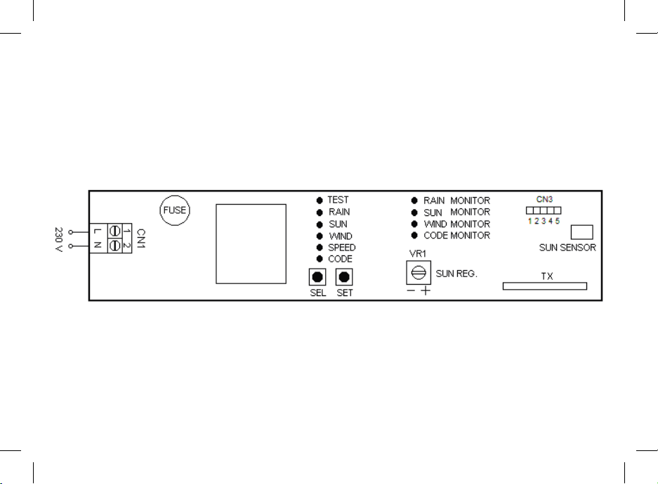
COLLEGAMENTI DELLA MORSETTIERA CN1:
1 : Ingresso linea 230V~ (Fase).
2 : Ingresso linea 230V~ (Neutro).
CONDIZIONE INIZIALE DI FUNZIONAMENTO
Il dispositivo può funzionare solamente in abbinamento a una o più centrali elettroniche
SEAV predisposte alla ricezione radio d’informazioni inerenti lo stato dei sensori. Per il
funzionamento, sarà necessario effettuare l’operazione di programmazione del Sensore
Wireless sulla centrale a cui si vuole abbinare (vedi par.“CODE Invio Radio Identificativo”).
Nella configurazione di fabbrica ogni esemplare prodotto di Sensore Wireless ha un iden-
tificativo diverso.
FUNZIONAMENTO SENSORE VENTO
Il dispositivo invierà alla centrale a cui è stato abbinato un comando di chiusura ogni qualvolta
viene superata la soglia Vento impostata.
FUNZIONAMENTO SENSORE SOLE
Il dispositivo invierà alla centrale a cui è stato abbinato un comando di discesa dopo 10
minuti di luminosità superiore alla soglia selezionata tramite il trimmer VR1 e visualizzata
tramite l’accensione del LED SUN MONITOR; invierà un comando di salita dopo 10 minuti
di luminosità inferiore alla soglia selezionata.
Selezione invio informazioni stato sensore Fast/Slow:
Il dispositivo, tramite il Connettore CN3 permette di selezionare l’invio radio di infor-
mazioni sullo stato del sensore Sole in modo veloce ( Fast = 2 minuti ) o lento ( Slow
= 10 minuti ).
Nella configurazione di fabbrica la selezione delle velocità di invio radio è di tipo Slow
(CN3 pos. 3 - 4 ), per velocizzare i tempi di reazione del sensore sole (comandi inviati ogni
2 minuti circa invece che ogni 10), posizionare CN3 pos. 4 - 5.
L’operazione va effettuata con il sensore non alimentato.
Regolazione della sensibilità al Sole (5 ¸ 40 Klux)
Il dispositivo permette la regolazione della soglia d’intervento per luminosità tramite il
trimmer VR1. L’accensione del LED SUN MONITOR sul dispositivo indica che l’intensità
del Sole supera la soglia d’intervento selezionata, in questo modo avremo un riferimento
alle attuali condizioni di luce per stabilire quella desiderata.
TASTI DI PROGRAMMAZIONE E LED DI SEGNALAZIONE
Tasto SEL: seleziona il tipo di funzione da memorizzare, la scelta è indicata dal lampeggio del
Led. Premendo più volte il tasto è possibile posizionarsi sulla funzione desiderata. La selezione
resta attiva per 15 secondi, visualizzata dal LED lampeggiante, trascorsi i quali la centrale ritorna
allo stato originario.
Tasto SET:
esegue la programmazione della funzione scelta con il tasto SEL.
Led di segnalazione:
Led acceso: opzione memorizzata.
Led spento: opzione non memorizzata.
Led lampeggiante: opzione selezionata.
———————————— MENU’ PRINCIPALE —————————————
Riferimento Led Led spento Led Acceso
1) CODE Invio RFID = OFF Invio RFID = ON
2) SPEED Sicurezza Vento 25 Km/h Sicurezza Vento Pgm.
3) WIND Sicurezza Vento = OFF Sicurezza Vento = ON
4) SUN Sensore Sole = OFF Sensore Sole = ON
5) RAIN Non usato Non usato
6) TEST Test Sensori = OFF Test Sensori = ON
1) CODE : ( Invio Radio Identificativo )
L’abbinamento del Sensore Wireless ad una centrale va eseguito nel seguente modo: sulla
centrale attivare la procedura di programmazione del Sensore Wireless ( vedi manuale tec-
nico della centrale ), posizionarsi con il tasto SEL sul lampeggio del LED CODE e premere il
tasto SET per circa 1-2 secondi: nello stesso tempo il Sensore invierà un codice identificativo
segnalato dal tremolio del LED CODE MONITOR.
Verificare che nella centrale abbinata vi sia conferma dell’ avvenuta programmazione del
Sensore ( vedi manuale tecnico della centrale). In questo modo il Sensore Wireless è abbi-
nato alla centrale ed invierà ad essa comandi dipendenti dalle condizioni metereologiche.
Ripetere l’operazione se si vuole programmare lo stesso Sensore su altre centrali.
2) SPEED : ( Programmazione soglia Sicurezza Vento )
Visualizzazione della soglia Vento programmata
La visualizzazione della selezione soglia Sicurezza vento è eseguita seguente modo: posizio-
narsi con il tasto SEL su LED SPEED, il led inizierà a fare un doppio lampeggio per un numero
di volte pari alla soglia di Sicurezza vento in memoria (ad ogni doppio lampeggio del LED
SPEED equivale un incremento di 5 Km/h), (esempio: 5 lampeggi di LED SPEED = 25 Km/h).

6
Selezione della soglia di Sicurezza vento da 5 a 40 Km/h
Il sensore è fornito con la soglia d’intervento della Sicurezza vento pari a 25 Km/h (LED
SPEED OFF).
La programmazione della selezione soglia Sicurezza vento è eseguita nel seguente modo:
posizionarsi con il tasto SEL su LED SPEED e premere tasto SET per avviare la procedura
di programmazione: allo stesso tempo il LED SPEED inizierà a fare un doppio lampeggio;
(ogni doppio lampeggio del LED SPEED equivale ad un incremento di 5 Km/h), premere il
tasto SET al raggiungimento della soglia desiderata; nello stesso momento si determinerà
la memorizzazione del valore selezionato e il LED SPEED rimarrà acceso (esempio: 5 doppi
lampeggi di LED SPEED = 25 Km/h).
È possibile ripetere l’operazione nel caso di un’errata programmazione.
3) WIND : (ON/OFF Sensore Vento)
Disattivazione del Sensore Vento
Il dispositivo è fornito con il Sensore Vento abilitato (LED WIND ON).
La disattivazione del Sensore Vento può essere eseguita nel seguente modo: posizionarsi
con il tasto SEL sul lampeggio del LED WIND e premere per un istante il tasto SET: nello
stesso tempo il LED WIND si spegnerà e la disattivazione del Sensore Vento sarà comple-
tata. È possibile ripetere l’operazione per attivare il Sensore Vento.
4) SUN : (ON/OFF Sensore Sole)
Abilitazione del Sensore Sole
Il dispositivo è fornito con il Sensore Sole disabilitato (LED SUN OFF).
L’abilitazione del Sensore Sole può essere eseguita nel seguente modo: posizionarsi con
il tasto SEL sul lampeggio del LED SUN e premere per un istante il tasto SET: nello stesso
tempo il LED SUN rimarrà acceso e l’abilitazione del Sensore Sole sarà completata. È
possibile ripetere l’operazione per disabilitare il Sensore Sole.
5) RAIN : Non Usato
6) TEST: ( ON/OFF Test Sensori )
Il dispositivo è fornito con il Test dei Sensori Vento – Sole disabilitato (LED TEST OFF).
L’attivazione del Test dei Sensori Vento – Sole – Pioggia può essere eseguita nel seguente
modo: posizionarsi con il tasto SEL sul lampeggio del LED TEST e premere per un istante il
tasto SET: nello stesso tempo il LED TEST si accenderà e l’attivazione del Test dei Sensori Ven-
to – Sole sarà completata. È possibile ripetere l’operazione per disattivare il Test dei Sensori.
Test Anemometro :
ruotare manualmente le palette dell’ Anemometro, nello stesso istante si otterrà l’accen-
sione del LED WIND MONITOR, segnalando l’invio radio delle informazioni necessarie
alla centrale abbinata ( segnalato dal tremolio del LED CODE MONITOR ), precedente-
mente configurata, comandando la salita per un tempo di 5 sec.
Test Sensore sole :
ruotare al massimo il trimmer VR1 in senso orario ( nella posizione + ), nello stesso istante
si otterrà l’accensione del LED SUN MONITOR, segnalando l’invio radio delle informa-
zioni necessarie alla centrale abbinata (segnalato dal tremolio del LED CODE MONITOR),
precedentemente configurata, comandando la discesa per un tempo di 5 sec. Ruotare il
trimmer VR1 in senso antiorario ( nella posizione - ), nello stesso istante si otterrà lo spe-
gnimento del LED SUN MONITOR segnalando l’invio radio le informazioni necessarie alla
centrale abbinata ( segnalato dal tremolio del LED CODE MONITOR ), precedentemente
configurata, comandando la salita per un tempo di 5 sec.
MONITOR SENSORI
La centrale presenta quattro Leds di segnalazione “ monitor “ con i quali è possibile
visualizzare la trasmissione radio delle informazioni relative ad ogni sensore.
————————————— LEDS MONITOR ————————————
Riferimento Led Led spento Led Acceso
CODE MONITOR Info = OFF Info = ON
WIND MONITOR Info = OFF Info = ON
SUN MONITOR Info = OFF Info = ON
RAIN MONITOR Non usato Non usato
RESET:
Nel caso sia opportuno ripristinare la centrale alla configurazione di fabbrica, premere il
tasto SEL e SET insieme in modo da ottenere l’accensione contemporanea di tutti i LED di
segnalazione e subito dopo lo spegnimento. Rev. 3.0 del 05/09/2016

WiSun Wireless Sensor S/F
Wind, Sun Wireless Sensor to be coupled with SEAV electronic control units
for the automation of rolling window shutters and sun blinds.
- Mod. WiSun S/F 433 : 433,92 MHz
important for the user:
- The device must never be used by chil-
dren or persons with reduced physical-
psychological abilities, unless supervised
or trained on the functioning and the use
modalities.
- Do not allow children to play with the
device.
- ATTENTION: keep this instruction manual
and respect the important safety pre-
scriptions contained herein. The non com-
pliance with the prescriptions may cause
damages and serious accidents.
- Frequently examine the plant to detect any
signs of damaging. Do not use the device
if a repair intervention is necessary.
attention:
Alloperations which requirethe
opening of the casing (cables connection,
programming, etc.) must be carried out by
expert personnel during installation. For
any further operation which requires the
casing to be re-opened (re-programming,
repair or installation amendments) contact
the after-sales assistance.
important for the installer
- The device must be permanently con-
nected to the power supply network and
not have any type of sectioning device of
the 230Vac electric line, it will therefore
be under the care of the installer, to pro-
vide the plant with a sectioning device.
It is necessary to install a single-phase
switch with over-voltage category III. It
must be positioned so as to be protected
against accidental closures.
GB
7

8
- For connections (power supply), use
flexible cables under insulating sheath
in harmonised polychloroprene (H05RN-
F) with minimum section of the conduc-
tors equal to 0,75 mm2.
- The connection cables must be fixed by
assembling cable clamps supplied with
the product.
- The device, at the time of installing,
must be carefully managed, ensuring
to have assembled the composing parts
correctly. Pay particular attention to the
ceramic plate and to the connecting
flat. When re-closing the box, the latter
must fold, on itself, in an orderly man-
ner.
- It is very important to establish the
exact location so that the product is
exposed to the same atmospheric
agents as when it is controlled.
- Do not paint or varnish the sensitive
surface of the control unit.
- The dirt which builds up on the rain sen-
sor surface limits the sensitivity: it is
therefore recommended to clean it once
or twice a year with a damp cloth, after
having disconnected the automation.
- For a correct functioning, it is recom-
mended to always use only one device
for one or more control units installed in
an action range of 20 meters.
- Always carry out the tests of the sen-
sors to ensure the correct functioning of
the installed system.
WiSun S/F 443
are in compliance with the specifics of
RED 2014/53/EU, EMC 2014/30/EU, LVD 2014/35/EU
Directives.

9
TECHNICAL DATA:
- Power supply : 230V~ 50/60Hz 3W max.
- Working temperature : -10 ÷ 55 °C
- Working frequency : see model
- Sensitivity Anemometer : 5 ÷ 40 Km/h
- Sun Sensor Sensitivity : 5 ÷ 40 Klux.
- Packaging dimensions : 240x185x110 mm.
- Container : PC UL94V-0 (IP54)
CONNECTIONS OF THE CN1 TERMINAL BOARD:
1 : 230V~ Line input (Phase).
2 : 230V~ Line input (Neutral).
INITIAL FUNCTIONING CONDITION
The device can only work in conjunction with one or more SEAV electronic control units pre-
arranged for radio reception of information relating to the state of the sensors. For the func-
tioning, it will be necessary to carry out the programming operation of the Wireless Sensor
on the control unit to which it will be coupled (see par.“CODE Sending of Radio Identifier” ).
In the default factory setting, each Wireless Sensor example produced has a different
identifier.
WIND SENSOR FUNCTIONING
The device will send to the control unit to which it has been coupled, a closing control every
time the set Wind threshold is exceeded.
SUN SENSOR FUNCTIONING
The device will send to the control unit to which it has been coupled, a downward control
after 10 minutes of brightness higher to the threshold selected by means of the VR1 trim-
mer and displayed through the switching on of the SUN MONITOR LED; it will send an
upward control after 10 minutes of brightness lower than the selected threshold.
Select send sensor status information Fast / Slow:
The device, through the Connector CN3 allows you to select the radio sending of informa-
tion about the status of Sun sensor so Fast (= 2 minutes) or slow (Slow = 10 minutes).
In the factory configuration the selection of radio transmission speed is kind of slow (CN3
pos. 3-4), to speed up the reaction time of the sun sensor (commands sent every 2 min-
utes about instead of every 10), place CN3 pos. 4-5.
The operation must be performed with the sensor is not powered.
Regulation of sensitivity to the Sun (5 ¸ 40 Klux)
The device allows to regulate the intervention threshold due to brightness, by means of
the VR1 trimmer. The switching on of the SUN MONITOR LED on the device indicates that
the Sun intensity exceeds the selected intervention threshold, in this way we will have a
reference to the current light conditions to establish the desired one
PROGRAMMING KEYS AND INDICATOR LED
SEL Key: selects the type of function to memorise, the choice is indicated by the flashing of the
LED. By repeatedly pressing the key, it is possible to position oneself on the desired function. The
selection remains active for 15 seconds, displayed by the flashing LED, after which the control
unit returns to the original status.
SET Key:
carries out the programming of the function chosen with the SEL key.
Indicator LED:
LED on: option memorised.
LED off: option not memorised.
LED flashing: option selected.
———————————— M A I N M E N U —————————————
LED Reference LED Off LED On
1) CODE Send RFID = OFF Send RFID = ON
2) SPEED Wind Safety 25 Km/h Pgm. Wind Safety
3) WIND Wind Safety = OFF Wind Safety = ON
4) SUN Sun Sensor = OFF Sun Sensor = ON
5) RAIN Not used Not used
6) TEST Test Sensors = OFF Test Sensors = ON
1) CODE : (Sending of Radio Identifier)
The coupling of the Wireless Sensor to a control unit must be carried out as follows: activate
the Wireless Sensor programming procedure on the control unit (see control unit technical
manual), with the SEL key position yourself on the flashing of the CODE LED and press the
SET key for about 1-2 seconds: at the same time, the Sensor will send an identifying code
signalled by the flickering of the CODE MONITOR LED.
Check that in the coupled control unit there is confirmation of the occurred Sensor program-
ming (see control unit technical manual). In this way, the Wireless Sensor is coupled to
the control unit and it will send to the same controls dependant upon the meteorological
conditions.
Repeat the operation in case the same Sensor is to be programmed on other control units.
2) SPEED : ( Programming of Wind Safety threshold )
Display of the programmed Wind threshold
The display of the wind Safety threshold selection is carried out as follows: with the SEL key
position yourself on SPEED LED, the LED will start to double flash for the number of times
equal to the wind Safety threshold in the memory (to every double flash of the SPEED LED
corresponds an increase of 5 Km/h), (example: 5 flashes of SPEED LED = 25 Km/h).

10
Selection of the wind Safety threshold from 5 to 40 Km/h
The sensor is supplied with the wind Safety intervention threshold equal to 25 Km/h
(SPEED OFF LED).
The programming of the wind Safety threshold selection is carried out as follows: with
the SEL key position yourself on SPEED LED and press the SET key to start the program-
ming procedure: at the same time, the SPEED LED will start to double flash; (every double
flash of the SPEED LED corresponds to an increase of 5 Km/h), once the desired threshold
has been reached, press the SET key; the selected value will be memorised at the same
time and the SPEED LED will remain on (example: 5 double flashes of SPEED LED = 25
Km/h).
It is possible to repeat the operation in case of an incorrect programming.
3) WIND : (Wind Sensor ON/OFF)
Deactivation of the Wind Sensor
The device is supplied with the Wind Sensor enabled (WIND ON LED).
The deactivation of the Wind Sensor can be carried out as follows: with the SEL key
position yourself on the flashing of the WIND LED and press the SET key for an instant: at
the same time, the WIND LED will switch off and the Wind Sensor deactivation will be
complete. It is possible to repeat the operation to activate the Wind Sensor.
4) SUN : (Sun Sensor ON/OFF)
Enabling the Sun Sensor
The device is supplied with the Sun Sensor disabled (SUN OFF LED).
The enabling of the Sun Sensor can be carried out as follows: with the SEL key position
yourself on the flashing of the SUN LED and press the SET key for an instant: at the same
time, the SUN LED will remain on and the Sun Sensor enabling will be complete. It is
possible to repeat the operation to disable the Sun Sensor.
5) RAIN : Not Used
6) TEST: (Test Sensors ON/OFF)
The device is supplied with the Wind - Sun Test Sensors disabled (TEST OFF LED).
The activation of the Wind - Sun - Rain Test Sensors can be carried out as follows: with
the SEL key position yourself on the flashing of the TEST LED and press the SET key
for an instant: at the same time, the TEST LED will switch on and the activation of the
Wind - Sun Test Sensors will be complete. It is possible to repeat the operation to disable
the Test Sensors.
Anemometer Test:
manually rotate the Anemometer blades and, at the same time, the WIND MONITOR LED
will switch on, signalling the radio sending of the necessary information to the previously
configured coupled control unit (signalled by the flickering of the CODE MONITOR LED),
controlling the ascent for 5 sec.
Sun Sensor Test:
rotate VR1 trimmer as far as possible clockwise (in + position) and, at the same time,
the SUN MONITOR LED will switch on, signalling the radio sending of the necessary
information to the previously configured coupled control unit (signalled by the flickering of
the CODE MONITOR LED), controlling the descent for 5 sec. Rotate the VR1 trimmer VR1
anti-clockwise (in - position) and, at the same time, the SUN MONITOR LED will switch
off, signalling the radio sending of the necessary information to the previously configured
coupled control unit (signalled by the flickering of the CODE MONITOR LED), controlling
the ascent for 5 sec.
SENSORS MONITOR
The control unit presents four “monitor” indicator LED with which it is possible to display
the radio transmission of the information relating to each sensor.
————————————— LEDS MONITOR ————————————
LED Reference LED Off LED On
CODE MONITOR Info = OFF Info = ON
WIND MONITOR Info = OFF Info = ON
SUN MONITOR Info = OFF Info = ON
RAIN MONITOR Not used Not used
RESET:
In case it is necessary to reset the control unit default factory configuration, press the
SEL and SET keys together so that all indicator LED switch on and off at the same time.
Rev. 3.0 05/09/2016

Capteur Wireless WiSun S/F
Capteur Wireless Vent, Soleil, à associer aux centrales électroniques SEAV
pour l’automatisation des stores et des volets roulants.
- Mod. WiSun S/F 433 : 433,92 MHz
informations importantes pour l’utilisateur
- Le dispositif ne doit pas être utilisé par
des enfants ou par des personnes aux
capacités psychophysiques réduites, à
moins qu’ils ne soient surveillés ou ins-
truits quant au fonctionnement et aux
modalités d’utilisation.
- Ne pas permettre aux enfants de jouer
avec le dispositif.
- ATTENTION: conserver ce livret d’ins-
tructions et respecter les importantes
prescriptions de sécurité qui y figurent.
Le non respect des prescriptions pourrait
provoquer des dommages et de graves
accidents.
- Examiner fréquemment l’installation pour
relever d’éventuels signes d’endomma-
gement. Ne pas utiliser le dispositif s’il
nécessite une intervention de réparation.
attention:
Toutes les opérations qui
exigent l’ouverture du boîtier (raccordement
de câbles, programmation, etc.) doivent
être effectuées au moment de l’installation
par le personnel qualifié. Pour toutes opé-
rations successives exigeant la réouverture
du boîtier (reprogrammation, réparation ou
modifications de l’installation) contacter le
service d’Assistance Technique.
informations importantes pour l’installateur
-Le dispositif doit être continuellement
branché au réseau d’alimentation et ne
doit présenter aucun type de dispositif de
sectionnement de la ligne électrique de
230 Vac,le technicien devra donc prévoir
dans l’installation un dispositif de section-
nement. Il est indispensable d’installer un
F
11

12
interrupteur omnipolaire de 3ième caté-
gorie de surtension. Celui-ci doit être
placé de façon à être protégé contre les
débranchements accidentels.
- Pour les branchements (alimentation) nous
conseillons d’utiliser des câbles flexibles
sous gaines isolantes en polychloroprène
de type harmonisé (H05RN-F) avec section
minimum des conducteurs de 0,75 mm2.
- La fixation des câbles de branchement, doit
être garantie par l’assemblage des serre-
câbles fournis à l’intérieur du produit.
- Au moment de l’installation le disposi-
tif doit être manipulé avec précaution en
s’assurant d’avoir assemblé correctement
les parties qui le composent. Faire particu-
lièrement attention à la plaque céramique
et au câble plat de raccordement. En refer-
mant le boîtier, veillez à ce que ce dernier
soit soigneusement replié sur lui-même.
- Il est très important d’établir l’empla-
cement idoine de façon que le produit
soit exposé aux agents atmosphériques
dont il doit effectuer le contrôle.
- Ne pas peindre ou vernir la superficie sen-
sible de la centrale.
- Les salissures qui s’accumulent sur
la superficie du capteur de la pluie en
limitent la sensibilité: nous conseillons,
par conséquent, de le nettoyer une à deux
fois par an avec un linge humide, après
l’avoir mis hors tension.
- Pour un correct fonctionnement, nous
conseillons toujours l’utilisation d’un
seul dispositif pour une ou pour plu-
sieurs centrales dans un rayon d’action
de 20 mètres.
- Effectuer toujours les tests des capteurs
de façon à confirmer le correct fonction-
nement du système installé.

13
CARACTÉRISTIQUES TECHNIQUES:
- Alimentation : 230V~ 50/60Hz 3W max.
- Température d’exercice : -10 ÷ 55 °C
- Fréquence d’exercice : voir modèle
- Sensibilité de l’Anémomètr : 5 ÷ 40 Km/h
- Sensibilité du Capteur Sole : 5 ÷ 40 Klux.
- Dimensions emballage : 240x185x110 mm.
- Boîte : PC UL94V-0 (IP54)
Branchements du Bornier CN1:
1 : Entrée ligne 230V~ ( Phase ).
2 : Entrée ligne 230V~ ( Neutre ).
CONDITION INITIALE DE FONCTIONNEMENT
Le dispositif peut fonctionner seulement associé à une ou plusieurs centrales électro-
niques SEAV prédisposées à la réception radio d’informations concernant l’état des
capteurs. Pour le fonctionnement, il suffira d’effectuer l’opération de programmation du
Capteur Wireless sur la centrale avec laquelle on veut l’associer (voir par. “CODE Envoi
Radio Identificateur”).
Dans la configuration de l’usine chaque exemplaire de Capteur Wireless produit a un
identificateur spécifique.
FONCTIONNEMENT CAPTEUR VENT
Le dispositif enverra à la centrale, à laquelle il est associé, une commande de fermeture toutes
les fois que la limite configurée de Vent est dépassée.
FONCTIONNEMENT CAPTEUR SOLEIL
Le dispositif enverra à la centrale à laquelle il est associé une commande de descente
après 10 minutes d’éclairage supérieur à la limite sélectionnée avec le trimmer VR1 et
visualisée au travers de l’allumage de la LED SUN MONITOR; il enverra une commande
de montée après 10 minutes d’éclairage inférieur au seuil sélectionné.
Sélectionner envoyer des informations sur l’état du capteur rapide / lente:
Le dispositif, à travers le CN3 Connector vous permet de sélectionner la radio d’envoyer
des informations sur l’état du capteur Sun si rapide (= 2 minutes) ou lente (slow = 10
minutes).
Dans la configuration usine de la sélection de la vitesse de transmission radio est un peu
lent (CN3 pos. 3-4), pour accélérer le temps de réaction du capteur solaire (commandes
envoyées toutes les 2 minutes environ au lieu de tous les 10), lieu CN3 pos. 4-5.
L’opération doit être effectuée avec le capteur n’est pas alimenté.
Réglage de la sensibilité au Soleil ( 5 ¸ 40 Klux )
Le dispositif permet de régler le seuil d’intervention selon l’éclairage au moyen du trim-
mer VR1. L’allumage de la LED SUN MONITOR sur le dispositif indique que l’intensité du
Soleil dépasse le seuil d’intervention sélectionné,de cette façon on se réfère aux condi-
tions actuelles de luminosité pour établir le seuil souhaité.
TOUCHES DE PROGRAMMATION ET LED DE SIGNALISATION
Touche SEL: sélectionne le type de fonction à mémoriser, le choix est indiqué par le
clignotement de la LED. En appuyant plusieurs fois sur la touche on peut se positionner
sur la fonction souhaitée. La sélection reste active pendant 15 secondes, visualisée par la
LED qui clignote, à la suite desquelles la centrale revient à son état primaire.
Touche SET:
effectue la programmation de la fonction choisie avec la touche SEL.
LED de signalisation:
LED allumée: option mémorisée.
LED éteinte: option non mémorisée.
LED clignotante: option sélectionnée.
———————————— MENU PRINCIPAL —————————————
Référence LED LED Eteinte LED Allumée
1) CODE Envoi RFID = OFF Envoi RFID = ON
2) SPEED Sécurité Vent 25 Km/h Sécurité Vent Pgm.
3) WIND Sécurité Vent = OFF Sécurité Vent = ON
4) SUN Capteur Soleil = OFF Capteur Soleil = ON
5) RAIN Non utilisé Non utilisé
6) TEST Test Capteurs = OFF Test Capteurs = ON
1) CODE : ( Envoi Radio Identificateur)
Le couplage du Capteur Wireless à une centrale doit être effectué de la façon suivante:
sur la centrale activer la procédure de programmation du Capteur Wireless (voir livret
technique de la centrale), se positionner avec la touche SEL sur la LED CODE qui clignote
et appuyer sur la touche SET pendant environ 1 à 2 secondes: simultanément le Capteur
enverra un code identificateur signalé par le scintillement de la LED CODE MONITOR.
WiSun S/F 443
sont conformes aux spécifications des Directives
RED 2014/53/EU, EMC 2014/30/EU, LVD 2014/35/EU.

14
Vérifier que dans la centrale associée apparaisse la confirmation de la programmation du
Capteur (voir livret technique de la centrale). De cette façon le Capteur Wireless est associé
à la centrale et lui enverra les commandes relatives aux conditions météorologiques.
Répéter l’opération si l’on veut programmer le même Capteur sur d’autres centrales.
2) SPEED : ( Programmation seuil Sécurité Vent)
Visualisation du seuil Vent programmé
La visualisation de la sélection du seuil Sécurité Vent est effectuée de la façon suivante:
se positionner avec la touche SEL sur LED SPEDD, la LED commencera à faire un double
clignotement pour un nombre de fois égal au seuil de Sécurité Vent en mémoire (chaque
double clignotement de la LED SPEED équivaut à une augmentation de 5 Km/h) (exemple: 5
clignotements de LED SPEED = 25 Km/h).
Sélection du seuil de Sécurité Vent de 5 à 40 Km/h
Le Capteur est livré avec le seuil d’intervention de la Sécurité Vent égal à 25 Km/h (LED
SPEED OFF).
La programmation de la sélection du seuil Sécurité Vent est effectuée de la façon sui-
vante: se positionner avec la touche SEL sur LED SPEED et appuyer sur la touche SET
pour mettre en fonction la procédure de programmation: simultanément la LED SPEED
commencera à faire un double clignotement; (chaque double clignotement de la LED
SPEED équivaut à une augmentation de 5 Km/h), appuyer sur la touche SET lorsque le
seuil souhaité est atteint; au même moment la mémorisation de la valeur sélectionnée
se déterminera et la LED SPEED restera allumée (exemple: 5 doubles clignotements de
la LED SPEED = 25 Km/h).
On peut répéter l’opération dans le cas d’une programmation erronée.
3) WIND : ( ON/OFF Capteur Vent )
Désactivation du Capteur Vent
Le dispositif est livré avec le Capteur Vent activé (LED WIND ON).
La désactivation du Capteur Vent peut être effectuée de la façon suivante: se positionner
avec la touche SEL sur le clignotement de la LED WIND et appuyer un instant sur la touche
SET: simultanément la LED WIND s’éteindra et la désactivation du Capteur Vent sera
complétée. On peut répéter l’opération pour activer le Capteur Vent.
4) SUN : ( ON/OFF Capteur Soleil )
Activation du Capteur Soleil
Le dispositif est livré avec le Capteur Soleil désactivé (LED SUN OFF).
L’activation du Capteur Soleil peut être effectuée de la façon suivante: se positionner
avec la touche SEL sur le clignotement de la LED SUN et appuyer un instant sur la touche
SET: simultanément la LED SUN restera allumée et l’activation du Capteur Soleil sera
complétée. On peut renouveler l’opération pour désactiver le Capteur Soleil.
5) RAIN : ( Non Utilisé )
6) TEST: ( ON/OFF Test Capteurs )
Le dispositif est livré avec le Test des Capteurs Vent - Soleil désactivé (LED TEST OFF).
L’activation du Test des Capteurs Vent - Soleil - Pluie peut être effectuée de la façon suivante:
se positionner avec la touche SEL sur le clignotement de la LED TEST et appuyer un instant sur
la touche SET: simultanément la LED TEST s’allumera et l’activation du Test des Capteurs Vent
- Soleil sera complétée. On peut renouveler l’opération pour désactiver le Test des Capteurs.
Test-de l’Anémomètre :
tourner manuellement les ailettes de l’Anémomètre, simultanément on obtiendra l’allu-
mage de la LED WIND MONITOR, en signalant l’envoi radio des informations nécessaires
à la centrale associée (signalé par le scintillement de la LED CODE MONITOR), configurée
au préalable, en commandant la montée pour un laps de temps de 5 sec.
Test Capteur Soleil:
tourner au maximum le trimmer VR1 dans le sens horaire (dans la position + ), simulta-
nément on obtiendra l’allumage de la LED SUN MONITOR, en signalant l’envoi radio des
informations nécessaires à la centrale associée (signalé par le scintillement de la LED CODE
MONITOR),auparavant configurée, en commandant la descente pour un laps de temps de 5
sec. Tourner le trimmer VR1 dans le sens anti-horaire (dans la position - ), simultanément on
obtiendra l’extinction de la LED SUN MONITOR en signalant l’envoi radio des informations
nécessaires à la centrale associée (signalé par le scintillement de la LED CODE MONITOR)
auparavant configurée, commandant la montée pour un laps de temps de 5 sec.
MONITOR DES CAPTEURS
La centrale présente quatre LEDS de signalisation “monitor” avec lesquelles on peut
visualiser la transmission radio des informations relatives à chaque capteur.
————————————— LEDS MONITOR ————————————
Référence LED LED Eteinte LED Allumée
CODE MONITOR Info = OFF Info = ON
WIND MONITOR Info = OFF Info = ON
SUN MONITOR Info = OFF Info = ON
RAIN MONITOR Non utilisé Non utilisé
RESET:
S’il était nécessaire de rétablir la centrale dans sa configuration d’usine appuyer sur les
touches SEL et SET ensemble de façon à obtenir l’allumage simultané de toutes les LEDS
de signalisation et immédiatement après leur extinction. Rev. 3.0 05/09/2016

Wireless-Sensor WiSun S/F
Wireless-Sensor für Wind und Sonne, zur Kombination mit elektronischen
Steuereinheiten von SEAV zur Steuerung von Rollläden und Markisen.
- Mod. WiSun S/F 433 : 433,92 MHz
Wichtige hinWeise für den nutzer
- Diese Vorrichtung darf nicht von Kindern
oder von Personen mit eingeschränkten
psychophysischen Fähigkeiten bedient
werden, es sei denn, unter Aufsicht oder
Unterweisung zu Funktion und Gebrauch
des Gerätes.
- Erlauben Sie Kindern nicht, mit dem Gerät
zu spielen.
- ACHTUNG: Bewahren Sie diese Bedie-
nungsanleitung bitte sorgfältig auf und
halten Sie sich strengstens an die darin
enthaltenen Sicherheitshinweise. Die
Nichteinhaltung dieser Vorgaben könnte
zu Schäden und schweren Unfällen führen.
- Kontrollieren Sie die Anlage regelmäßig
und in kurzen Zeitabständen auf Zeichen für
Beschädigungen. Verwenden Sie das Gerät
nicht, wenn eine Reparatur erforderlich ist.
achtung:
Alle Arbeiten, die ein Öffnen des
Gehäuses erforderlich machen (Anschluss
von Kabeln, Programmierung usw.), müs-
sen bei der Installation durch erfahrenes
Fachpersonal ausgeführt werden. Für
alle weiteren Arbeiten, die eine erneutes
Öffnen des Gehäuses erfordern (Neupro-
grammierung, Reparatur oder Änderungen
der Installation) wenden Sie sich bitte an
den technischen Kundendienst.
Wichtige hinWeise für den installateur
-Das Gerät muss permanent mit dem
Stromversorgungsnetz verbunden sein
und weist keinerlei Trennvorrichtung zur
Trennung von der 230-VAC-Leitung auf. Es
ist daher Aufgabe des Installateurs, eine
Trennvorrichtung zu installieren. Es ist
D
15

16
ein allpoliger Unterbrecherschalter der
Überspannungskategorie III einzubau-
en. Dieser ist so anzuordnen, dass er
gegen versehentliches Wiedereinschal-
ten geschützt ist.
- Für den Anschluss (Stromversorgung)
wird die Verwendung flexibler Kabel mit
Isoliermantel aus Polychloropren des
genormten Typs H05RN-F mit Mindestlei-
terquerschnitt von 0,75 mm2 empfohlen.
- Um die Befestigung der Anschlusskabel zu
gewährleisten, ist die dem Produkt beige-
legte Kabelschelle anzubringen.
- Das Gerät ist bei der Installation mit Vor-
sicht zu handhaben. Dabei ist auf einen
korrekten Zusammenbau zu achten. Ach-
ten Sie besonders auf das Keramikplätt-
chen und das Anschluss-Flachkabel. Die-
ses muss sich beim Schließen der Dose
ordentlich aufeinander falten.
- Die Wahl des Installationsortes ist
äußerst wichtig, da das Produkt den
Wettereinflüssen ausgesetzt sein muss,
die es erfassen soll.
- Die Sensorfläche der Steuereinheit darf
nicht angestrichen oder lackiert werden.
- Schmutzablagerungen auf der Oberfläche
des Regensensors beeinträchtigen des-
sen Empfindlichkeit: Er sollte daher ein
oder zweimal jährlich mit einem feuchten
Tuch gereinigt werden. Dazu ist die Strom-
versorgung der Anlage auszuschalten.
- Für einen einwandfreien Betrieb empfeh-
len wir stets den Einsatz nur eines einzi-
gen Geräts für eine oder mehrere in einem
Aktionsradius von 20 Metern installierte
Steuereinheiten.
- Führen Sie bitte stets die Tests der Sen-
soren aus, um die einwandfreie Funktion
des installierten Systems sicherzustellen.
17
TECHNISCHE EIGENSCHAFTEN:
- Stromversorgung : 230V~ 50/60Hz 3W max.
- Betriebstemperatur : -10 ÷ 55 °C
- Frequenz : Siehe Modell
- Empfindlichkeit des Windmessers : 5 ÷ 40 Km/h
- Empfindlichkeit des Sonnensensors : 5 ÷ 40 Klux.
- Abmessungen der Verpackung : 240x185x110 mm.
- Gehäuse : PC UL94V-0 (IP54)
Anschlüsse des Klemmenbretts CN1:
1 : Eingang 230V~Leitung (Phase).
2 : Eingang 230V~Leitung (Nullleiter).
ANFÄNGLICHER FUNKTIONSZUSTAND
Das Gerät funktioniert nur in Verbindung mit einer oder mehreren elektronischen SEAV-
Steuereinheiten, die für den Funkempfang von Informationen zum Zustand der Sensoren
eingerichtet sind. Für den Betrieb muss der Wireless-Sensor an der Steuereinheit, mit der
er verbunden werden soll, programmiert werden (siehe Abschn. “CODE Funkübertragung
der Kennung“).
In der Werkseinstellung hat jedes Produktexemplar des Wireless-Sensors eine andere
Kennung.
FUNKTIONSWEISE WINDMESSER
Jedes Mal, wenn die eingestellte Windschwelle überschritten wird, sendet das Gerät an die
Steuereinheit, mit der es verbunden ist, den Befehl zum Schließen.
FUNKTIONSWEISE SONNENSENSOR
Nach 10 Minuten mit einer Lichtstärke über der mit dem Trimmer VR1 eingestellten
Schwelle, die auch durch das Aufleuchten der LED SUN MONITOR angezeigt wird, sendet
das Gerät an die Steuereinheit, mit der es verbunden ist, den Befehl zum Ausfahren;
nach 10 Minuten mit einer Lichtstärke unter der eingestellten Schwelle sendet es den
Befehl zum Einfahren.
Wählen Sie senden Informationen zum Status des Fast / Slow:
Die Einrichtung, die durch den Anschluss CN3 können Sie wählen, das Radio sendet von
Informationen über den Status von Sun Sensor so schnell (= 2 Minuten) oder langsam
(Slow = 10 Minuten).
In der Werkseinstellung die Auswahl der Funkübertragung Geschwindigkeit ist etwas
langsam (CN3 pos. 3-4), zur Beschleunigung der Reaktionszeit von der Sonne Sensor
(gesendeten Befehle alle 2 Minuten statt alle über 10), Platz CN3 pos. 4-5.
Der Betrieb muss der Sensor nicht mit Strom versorgt durchgeführt werden.
Einstellung der Sonnenempfindlichkeit ( 5 ¸ 40 kLux )
Die Lichtstärke-Auslöseschwelle des Geräts kann mit Trimmer VR1 eingestellt werden.
Das Aufleuchten der LED SUN MONITOR am Gerät zeigt an, dass die Lichtstärke der
Sonne die gewählte Auslöseschwelle überschritten hat. Auf diese Weise hat man einen
Bezug zu den aktuellen Lichtbedingungen, um die gewünschte Schwelle festzulegen.
PROGRAMMIERTASTEN UND ANZEIGE-LED
SEL-Taste: Zur Wahl der zu speichernden Funktionsart, die Wahl wird durch das Blinken
der LED angezeigt. Durch mehrmaliges Drücken der Taste kann die gewünschte Funktion
angewählt werden. Die Auswahl bleibt 15 Sekunden lang aktiv, was durch das Blinken der
LED angezeigt wird, danach kehrt die Steuereinheit in den ursprünglichen Zustand zurück.
SET-Taste:
Zur Programmierung der mit der SEL-Taste gewählten Funktion.
Anzeige-LED:
LED leuchtet: Option gespeichert.
LED aus: Option nicht gespeichert.
LED blinkt: Option gewählt.
———————————— HAUPTMENÜ —————————————
LED-Anzeige LED aus LED leuchtet
1) CODE RFID senden = OFF RFID senden = ON
2) SPEED Windsicherheit 25 Km/h Windsicherheit Pgm.
3) WIND Windsicherheit = OFF Windsicherheit = ON
4) SUN Sonnensensor = OFF Sonnensensor = ON
5) RAIN Nicht verwendet Nicht verwendet
6) TEST Sensorentest = OFF Sensorentest = ON
1) CODE : (Funkübertragung der Kennung)
Die Zuordnung des Wireless-Sensors zu einer Steuereinheit erfolgt folgendermaßen: An
der Steuereinheit die Prozedur zur Programmierung des Wireless-Sensors aktivieren (siehe
technische Anleitung der Steuereinheit), mit der SEL-Taste die blinkende LED CODE anwäh-
len und die SET-Taste etwa 1-2 Sekunden lang drücken: Gleichzeitig sendet der Sensor einen
Kenncode, was durch das Flimmern der LED CODE MONITOR angezeigt wird.
WiSun S/F 443
den Bestimmungen den
RED 2014/53/EU, EMC 2014/30/EU, LVD 2014/35/EU
(Niederspannung) entspricht

18
Sicherstellen, dass an der Steuereinheit die erfolgte Programmierung des Sensors bestätigt
wurde (siehe technische Anleitung der Steuereinheit). Auf diese Weise ist der Wireless-
Sensor der Steuereinheit zugeordnet und sendet an diese die von den Wetterbedingungen
abhängigen Befehle.
Diese Prozedur ist zu wiederholen, wenn derselbe Sensor auf weitere Steuereinheiten pro-
grammiert werden soll.
2) SPEED : ( Programmierung der Windsicherheitsschwelle )
Anzeige der programmierten Windschwelle
Die Anzeige der gewählten Windsicherheitsschwelle erfolgt folgendermaßen: Mit der
SEL-Taste die LED SPEED anwählen, die LED beginnt doppelt zu blinken, die Anzahl der
doppelten Blinksignal entspricht der gespeicherten Windsicherheitsschwelle (jedem dop-
pelten Aufblinken der LED SPEED entspricht eine Erhöhung um 5 km/h), (Beispiel: 5-maliges
Blinken der LED SPEED = 25 km/h).
Wahl der Windsicherheitsschwelle von 5 bis 40 km/h
Bei der Lieferung ist die Auslöseschwelle der Windsicherheit des Sensors auf 25 km/h
eingestellt (LED SPEED OFF).
Die Programmierung der Windsicherheitsschwelle erfolgt folgendermaßen: Mit der SEL-
Taste die LED SPEED anwählen und die SET-Taste drücken, um die Programmierproze-
dur zu starten: Gleichzeitig beginnt die LED SPEED doppelt zu blinken; (jedes doppelte
Aufblinken der LED SPEED entspricht einer Erhöhung um 5 km/h), bei Erreichen der
gewünschten Schwelle die SET-Taste drücken; gleichzeitig erfolgt die Speicherung des
gewählten Wertes und die LED SPEED bleibt erleuchtet (Beispiel: 5-maliges doppeltes
Blinken der LED SPEED = 25 km/h).
Diese Prozedur kann im Falle einer falschen Programmierung wiederholt werden.
3) WIND : (Windmesser ON/OFF)
Deaktivierung des Windmessers
Das Gerät wird mit aktiviertem Windmesser (LED WIND ON) geliefert.
Die Deaktivierung des Windmessers kann folgendermaßen erfolgen: Mit der SEL-Taste
die blinkende LED WIND anwählen und einen Augenblick lang die SET-Taste drücken:
Gleichzeitig erlischt die LED WIND und die Deaktivierung des Windmessers ist abge-
schlossen. Zum Aktivieren des Windmessers kann die Prozedur wiederholt werden.
4) SUN : (Sonnensensor ON/OFF)
Aktivierung des Sonnensensors
Das Gerät wird mit deaktiviertem Sonnensensor (LED SUN OFF) geliefert.
Die Aktivierung des Sonnensensors kann folgendermaßen erfolgen: Mit der SEL-Taste die
blinkende LED SUN anwählen und einen Augenblick lang die SET-Taste drücken: Gleich-
zeitig bleibt die LED SUN erleuchtet und die Aktivierung des Sonnensensors ist abge-
schlossen. Zum Deaktivieren des Sonnensensors kann die Prozedur wiederholt werden.
5) RAIN : (Nicht verwendet)
6) TEST: (Sensorentest ON/OFF)
Das Gerät wird mit deaktiviertem Test von Windmesser und Sonnensensor (LED TEST OFF)
geliefert.
Die Aktivierung des Tests von Wind-, Niederschlagsmesser und Sonnensensor kann folgender-
maßen erfolgen: Mit der SEL-Taste die blinkende LED TEST anwählen und einen Augenblick
lang die SET-Taste drücken: Gleichzeitig leuchtet die LED TEST auf und die Aktivierung des
Tests von Windmesser und Sonnensensor ist abgeschlossen. Zum Deaktivieren des Sensoren-
tests kann die Prozedur wiederholt werden.
Test Windmesser:
Mit der Hand die Schaufeln des Windmessers drehen, gleichzeitig leuchtet die LED WIND
MONITOR auf und zeigt damit die Funkübertragung der erforderlichen Informationen zur
zugeordneten Steuereinheit an (was durch das Flimmern der LED CODE MONITOR ange-
zeigt wird), die vorher konfiguriert wurde, und löst 5 Sekunden lang das Einfahren aus.
Test Sonnensensor:
Trimmer VR1 im Uhrzeigersinn (in Position +) auf das Maximum drehen, im selben
Moment leuchtet die LED SUN MONITOR auf und zeigt damit die Funkübertragung der
erforderlichen Informationen zur zugeordneten Steuereinheit an (was durch das Flimmern
der LED CODE MONITOR angezeigt wird), die vorher konfiguriert wurde, und löst 5 Sekun-
den lang das Ausfahren aus. Trimmer VR1 gegen den Uhrzeigersinn (in Position -) drehen,
im selben Moment erlischt die LED SUN MONITOR auf und zeigt damit die Funkübertra-
gung der erforderlichen Informationen zur zugeordneten Steuereinheit an (was durch das
Flimmern der LED CODE MONITOR angezeigt wird), die vorher konfiguriert wurde, und löst
5 Sekunden lang das Einfahren aus.
SENSOREN-MONITOR
Die Steuereinheit besitzt vier „Monitor“-Anzeige-LEDs, mit denen die Funkübertragung
der Informationen zu jedem Sensor angezeigt werden kann.
————————————— MONITOR-LEDS ————————————
LED-Anzeige LED aus LED leuchtet
CODE MONITOR Info = OFF Info = ON
WIND MONITOR Info = OFF Info = ON
SUN MONITOR Info = OFF Info = ON
RAIN MONITOR Nicht verwendet Nicht verwendet
RESET:
Sollte es erforderlich sein, die Steuereinheit auf die Werkseinstellung zurückzusetzen,
SEL- und SET-Taste gleichzeitig drücken, so dass alle Anzeige-LEDs gleichzeitig aufleuch-
ten und gleich danach erlöschen. Rev. 3.0 05/09/2016

Sensor Inalámbrico WiSun S/F
Sensor Inalámbrico de Viento, Sol, para emplear combinado con centrales
electrónicas SEAV para la automatización de persianas arrollables y toldos.
- Mod. WiSun S/F 433 : 433,92 MHz
importante para el usuario
- El dispositivo no debe ser utilizado por
niños o por personas con capacidades
psicofísicas reducidas, a menos que estén
vigilados o hayan sido instruidos sobre el
funcionamiento y las modalidades de uso.
- No permitir que los niños jueguen con el
dispositivo.
- ATENCIÓN: Guardar este manual de ins-
trucciones y respetar las indicaciones
sobre seguridad que contiene. El no cum-
plimiento de las indicaciones podría gene-
rar daños y graves accidentes.
- Controlar periódicamente el equipo a fin
de detectar posibles averías. No utilizar
el dispositivo si es necesario realizar una
reparación.
atención:
Todas las operaciones que
requieren la abertura de la cubierta (cone-
xión de cables, programación, etc.) deben
ser realizadas en fase de instalación por
personal experto. Para cualquier otra
operación que requiera nuevamente la
abertura de la cubierta (reprogramación,
reparación o modificación de la instala-
ción) contacte la asistencia técnica
importante para el instalador
-El dispositivo debe estar conectado per-
manentemente a la red de alimentación
y no cuenta con ningún tipo de dispositivo
de seccionamiento de la línea eléctrica
230 Vac, por tanto, será responsabilidad
del instalador posicionar un dispositivo
de seccionamiento en la instalación. Es
necesario instalar un interruptor omni-
polar con categoría III de sobretensión.
El mismo se debe posicionar de manera
E
19

20
tal que esté protegido contra los cierres
accidentales.
- Para las conexiones (alimentación) se
recomienda usar cables flexibles con
envoltura aislante de policloropreno
de tipo armonizado (H05RN-F), con
sección mínima de los conductores
igual a 0,75 mm2.
- La fijación de los cables de conexión debe
garantizarse mediante el ensamble de las
abrazaderas de cable proporcionadas en el
interior del producto.
- Cuando se instala el dispositivo debe
manejarse con cuidado, asegurándose
de haber ensamblado correctamente las
partes que lo componen. Preste aten-
ción especialmente a la placa cerámica
y al flat de conexión. Cuando se vuelve a
cerrar la caja, este último debe doblarse
ordenadamente sobre sí mismo.
- Es muy importante establecer la exacta
localización de modo que el producto
quede expuesto a los agentes atmosfé-
ricos que debe controlar.
- No pinte la superficie sensible de la
central.
- La suciedad que se acumula sobre la
superficie del sensor de lluvia limita
la sensibilidad: por tanto, se aconseja
limpiarlo una o dos veces al año con un
paño húmedo después de desconectar
la automación.
- Para un funcionamiento correcto, se
recomienda siempre el uso de un solo
dispositivo para una o más centrales
instaladas en un radio de acción de 20
metros.
- Realice siempre los tests de los senso-
res, para asegurar el funcionamiento
correcto del sistema instalado.
This manual suits for next models
1
Table of contents
Languages:
Other Seav Accessories manuals


