SEB ARNO KRUPS Nescafe Dolce Gusto KP10 Series User manual

SEB INTERNATIONAL SERVICE
KP10XXXX
PJ10XXXX
1

Service manual
CONTENTS
Main Components................................................................................................. 3
Overview of external parts............................................................................................ 3
Overview of internal parts............................................................................................. 4
Water circuit.................................................................................................................. 5
Technical data .............................................................................................................. 6
Operating.................................................................................................................. 8
Machine status..............................................................................................................8
Preparation, first use ..................................................................................................... 9
Preparing a beverage................................................................................................. 11
Economy mode (auto shut-off function) ..................................................................... 13
Empty fluid system for shipping.................................................................................. 14
Troubleshooting................................................................................................... 15
Repair....................................................................................................................... 19
Tools and repair accessories...................................................................................... 19
Repair work without disassembling the machine ....................................................... 19
Cleaning or replacing injector plate, deblocking of injector.................................... 19
General disassembly.................................................................................................. 22
Replacing water tank connector................................................................................. 27
Replacing pump ......................................................................................................... 28
Replacing NTC temperature sensor........................................................................... 32
Replacing thermoblock............................................................................................... 34
Replacing power cord with thermo fuses ................................................................... 34
Replacing power button assembly ............................................................................. 36
Replacing electronic mainboard................................................................................. 37
Replacing locking handle ........................................................................................... 40
Replacing extraction head.......................................................................................... 41
Wiring diagram..................................................................................................... 44
Function Tests........................................................................................................45
Function test equipment............................................................................................... 45
Heating up time............................................................................................................ 46
Water temperature....................................................................................................... 47
Maintenance............................................................................................................48
Descaling..................................................................................................................... 48
Daily care and final cleaning........................................................................................ 51
2
Service manual
MAIN COMPONENTS
MAIN COMPONENTS
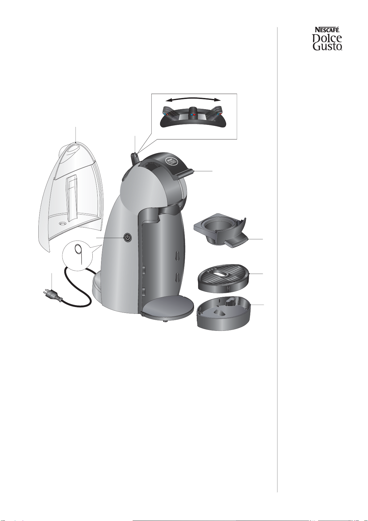
Overview of external parts
1. Water tank
2. Selection lever (cold / stop / hot)
3. Locking handle
4. Capsule holder
5. Drip grid
6. Drip tray
7. Power cord (e.g. with Swiss power plug)
8. Cleaning needle
9. Power button, illuminated
2
9
5
6
4
3
1
8
7
Cold Stop Hot
3
Service manual
MAIN COMPONENTS
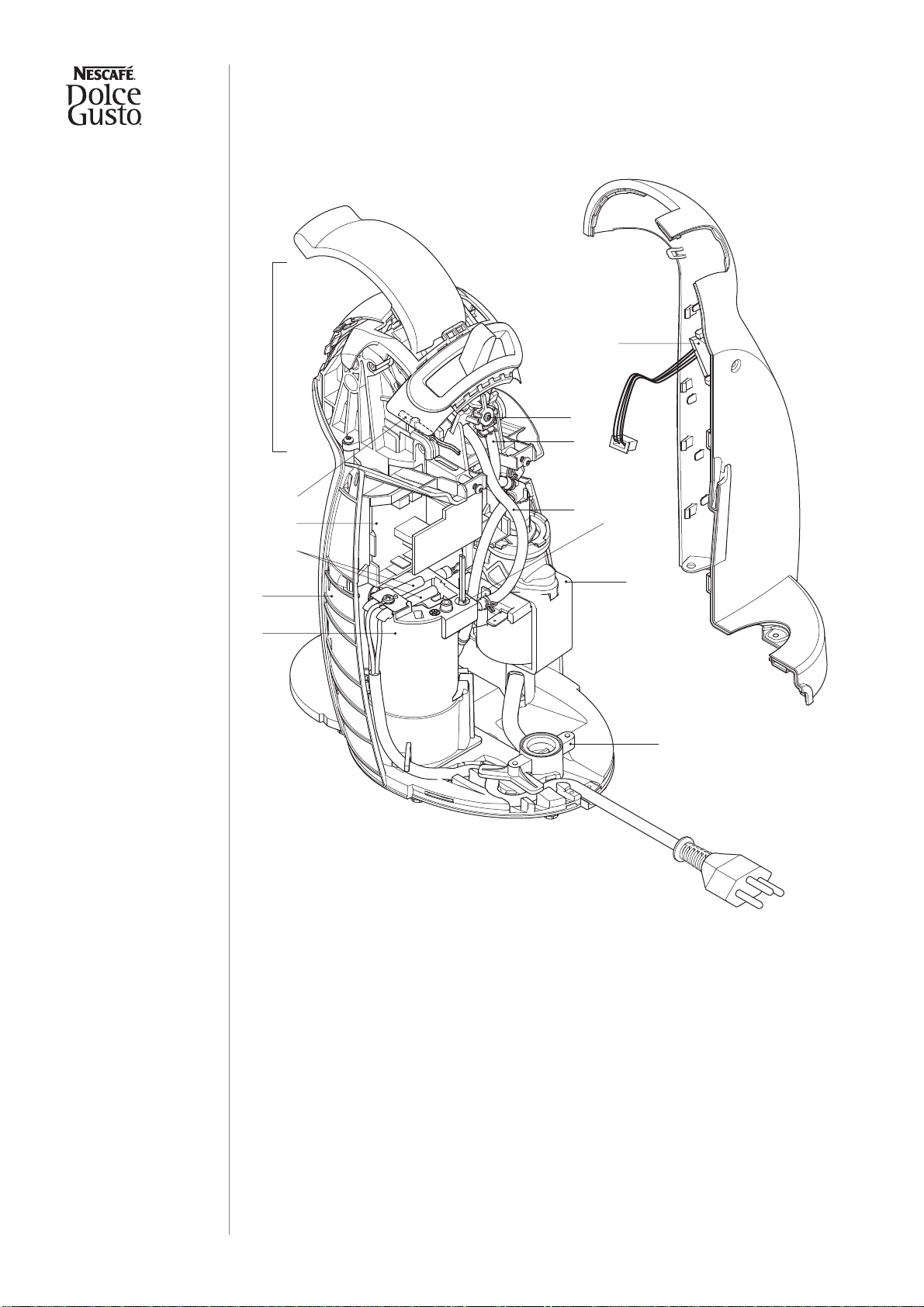
Overview of internal parts
1. Extraction head assembly
2. Reed sensor
3. Electronic main board with support
4. Thermo fuses (2x)
5. Main housing
6. Thermoblock
7. Power button assembly
8. Valve micro switch
9. Cold water pressure hose
10. Hot water pressure hose
11. NTC temperature sensor
12. Pump
13. Water tank connector
5
4
1
8
2
9
10
12
11
13
3
7
6
4

Service manual
MAIN COMPONENTS
Water circuit
1.Water tank with valve
2.Filter and connector
3.Pump
4.Thermoblock
5.Selection lever
6.Position cold
7.Position hot
8.Fconnector
9.Injector plate
10.Capsule holder
11.Injector
12. Capsuleholder
1
2
3
4
5
7
9
6
11
8
10
5

Service manual
MAIN COMPONENTS
Technical data
Mains voltage
Europe (UK, CH, DE, AT, FR, ES, PT, IT, NL, LU, BE, NO, SE, FI, DK,
GR, CZ, SK, PL, HU, RU, UA, LT, LV, EE, BG, RO, SI, BiH, SRB, HR)... 230 V / 50 Hz
USA / Canada...........................................................................................120 V / 60 Hz
Hong Kong.......................................................................................220 - 240 V / 50 Hz
Mexico..................................................................................................127 V / 50/60 Hz
Chile..........................................................................................................220 V / 50 Hz
Approvals.......................................................................VDE, SEV, CE, UL, CUL, JET
Power consumption
Europe ......................................................................................................max. 1’500 W
USA / Canada / Mexico.............................................................................max. 1’460 W
Hong Kong................................................................................................max. 1’500 W
Chile..........................................................................................................max. 1’340 W
Ratings (approx.)
Preheating ..........................................................................................................8.0 Wh
1 small cup (40 ml, Espresso) ............................................................................3.0 Wh
1 large cup (110 ml, Lungo) ................................................................................ 8.3 Wh
1 travel mug (350 ml, Powder)..........................................................................25.0 Wh
Economy mode.....................................................................................................0.1 W
Flow rates (± 50 ml/min)
R&G / Espresso ...............................................................210 ml/min at approx. 8.0 bar
R&G / Lungo ....................................................................230 ml/min at approx. 7.5 bar
R&G / Cappuccino ...........................................................210 ml/min at approx. 8.5 bar
R&G / Latte Macchiato.....................................................210 ml/min at approx. 7.5 bar
Powder / Milk....................................................................320 ml/min at approx. 3.5 bar
Capacities
Water tank................................................................................................................0.6 l
Drip tray.....................................................................................................approx. 70 ml
Temperatures
Safety temperature (thermal cut-off)......................................................133 °C (271 °F)
Hot beverage outlet temperature .....................................85 °C ± 5 °C (185 °F ± 41 °F)
Permissible ambient temperature ......................................5 °C - 45 °C (41 °F - 113 °F)
6

Service manual
MAIN COMPONENTS
Various data
Pre-heating time.....................................................................................approx. 30 sec.
Pump pressure max.................................................................................13.5 ± 1.5 bar
Noise....................................................................................................... max. 65 dB(A)
Dimensions [mm]
Dimensions (D x W x H).................................................................220 x 159 x 287 mm
Power cord length ....................................................................................... approx. 1 m
Weight of machine (without water).......................................................... approx. 2.4 kg
Distance from drip grid to coffee outlet [mm]
Espresso.......77 mm
Mug.............120 mm
Tall glass .....150 mm
Higher cup...177 mm
220
287
159
77
120
150
177
7

Service manual
OPERATING
OPERATING
Machine status
After switching on, an automatic self-test is performed to check if the
- capsule holder is inserted (with reed sensor)
- NTC is connected,
- NTC is not short circuited,
- the thermoblock reaches the working temperature in about 30 seconds.
Operatingmodes anddetectedfailures areindicatedbyLED signalsofthe powerbutton
as listed in the following table:
Operating modes Power button LED signals
Economy mode / Off —
Heating up / self-test red, blinking, approx. 30 sec.
Ready green, steady
After beverage preparation
(cool-down time) red, blinking, approx. 5 sec.
Descaling ready and during
descaling cycle green, slow blinking
Error mode red, rapid blinking
8

Service manual
OPERATING
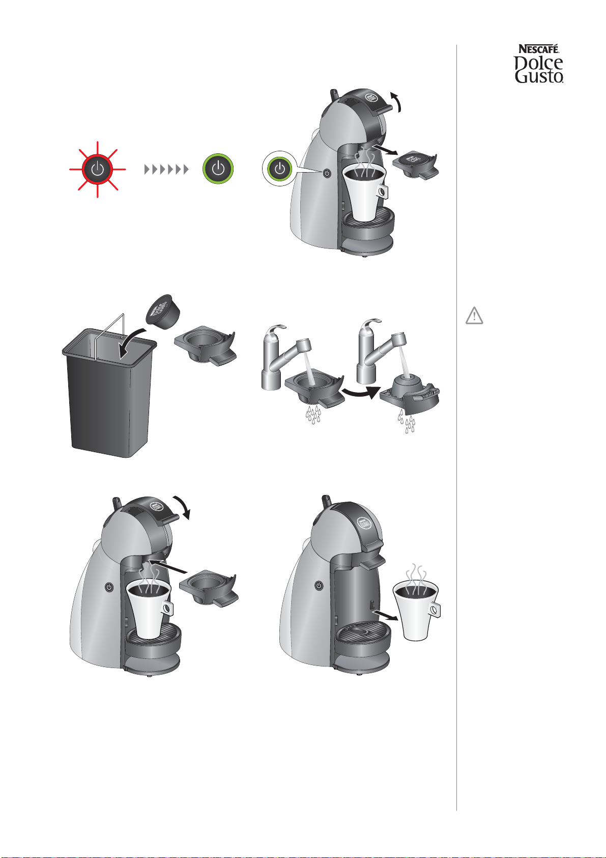
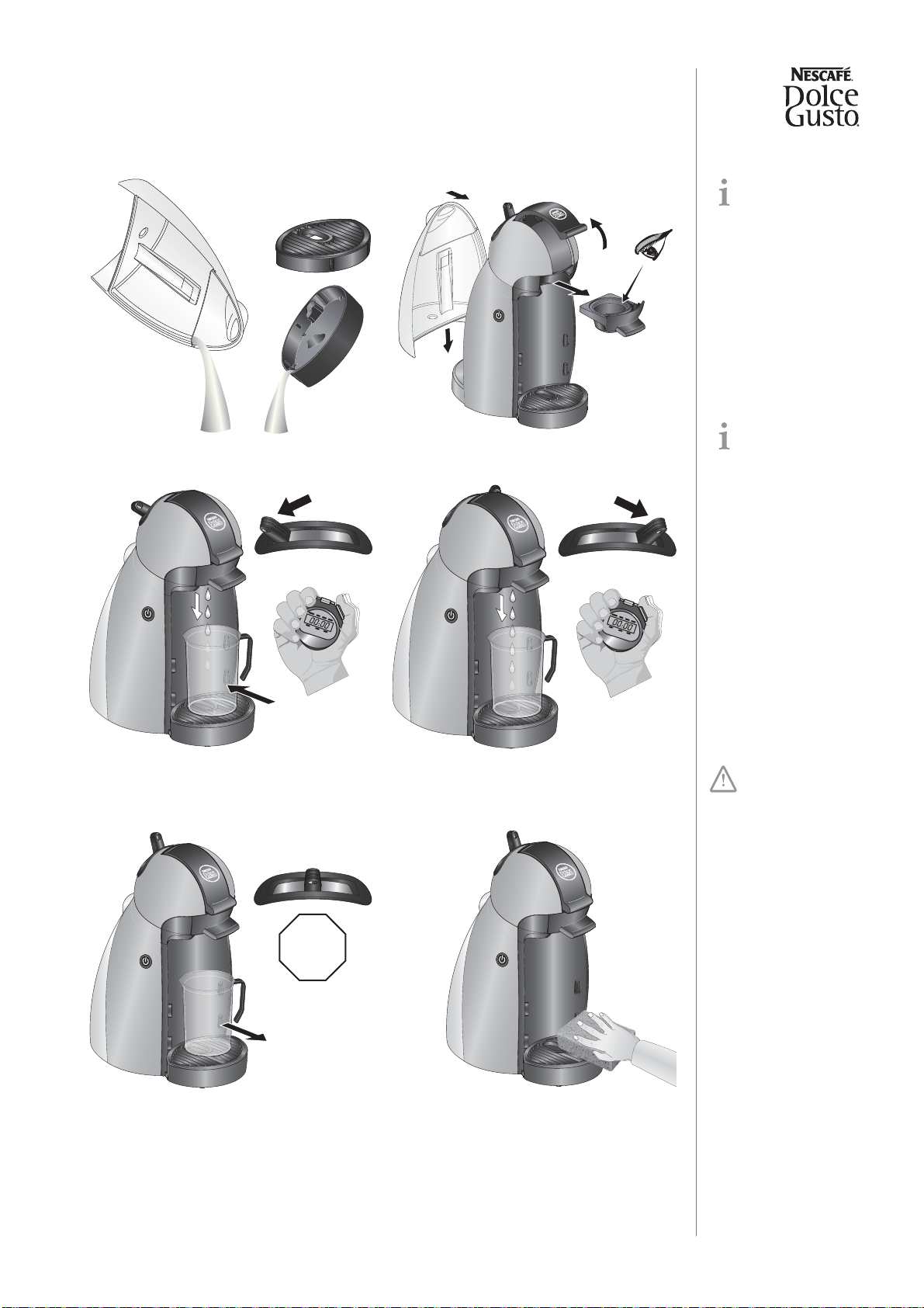
Preparation, first use
The new machine has to be rinsed properly before first use according to the following
sequence:
A timer or stop
watch is helpful to
observe the rinsing
times.
The machine will
not work without a
capsule holder inserted.
Do not insert a
capsule yet.
The pre-heating
time is approx.
30 sec.
1. Rinse water tank at first. Then fill
water tank up to max. level with
fresh, potable water.
2. Insert water tank.
3. Open locking handle.
4. Check that capsule holder is empty
(no capsule) for the following rinsing
procedure.
5. Insert capsule holder and close
locking handle.
6. Make sure that selection lever is in
central position.
7. Connect mains plug.
8. Place a jug with enough capacity
under outlet. 9. Switch machine ON.
10. Wait till power button lights up green.
MAX
MAX
9

Service manual
OPERATING
The drip tray is
height-adjustable in
3 levels.
11. Set selection lever to position "cold
water". Let water run through for
approx. 45 sec.
12. Set selection lever to position "hot
water". Let water run through for
approx. 45 sec.
13. Set selection lever to middle position
to stop rinsing.
14. Remove and empty jug.
15. Refill water tank.
16. Reinstall water tank. 17.
Adjust position of drip tray to cup size.
The machine is now ready for use.
~ 45 sec
~ 45 sec
STOP
MAX
MAX
10

Service manual
OPERATING
Preparing a beverage
Choose an
appropriate cup
size for beverage.
The locking handle
can only be
actuated if the selection
lever is in the middle
position.
Users allergic to
dairy products:
clean capsule holder
under running water
before use.
For filling amounts
see product package
of capsule or user manual.
The flow speed
depends on the
used capsule.
T
he machine does
not turn off auto-
matically.
Danger of hot
water and product
splashes - capsule can
burst.
Do not open locking
handle prematurely.
1. Check if water tank is filled.
2. Check if machine is ON and ready.
3. Re-adjust drip tray if necessary.
4. Place a cup under outlet.
5. Open locking handle and pull out
capsule holder.
6. Insert a capsule in capsule holder.
7. Insertcapsuleholderinmachineand
close locking handle.
8. Set selection lever to position "cold
water" or "hot water", depending on
beverage.
9. Push selection lever back to middle
position after specified filling amount
is in cup.
10. Do not open locking handle before
the power button stops blinking red
and turns to green.
STOP
11
Service manual
OPERATING
Risk of burning
from hot capsule.
Do not touch capsule
immediately after use.
11. Wait until power button lights up
green (approx. 5 sec). 12. Open locking handle and pull out
capsule holder.
13. Discard capsule in capsule bin. 14. Clean capsule holder.
15. Reinstall capsule holder or proceed
with second capsule of beverage. 16. Remove cup.
5 sec
12
Service manual
OPERATING
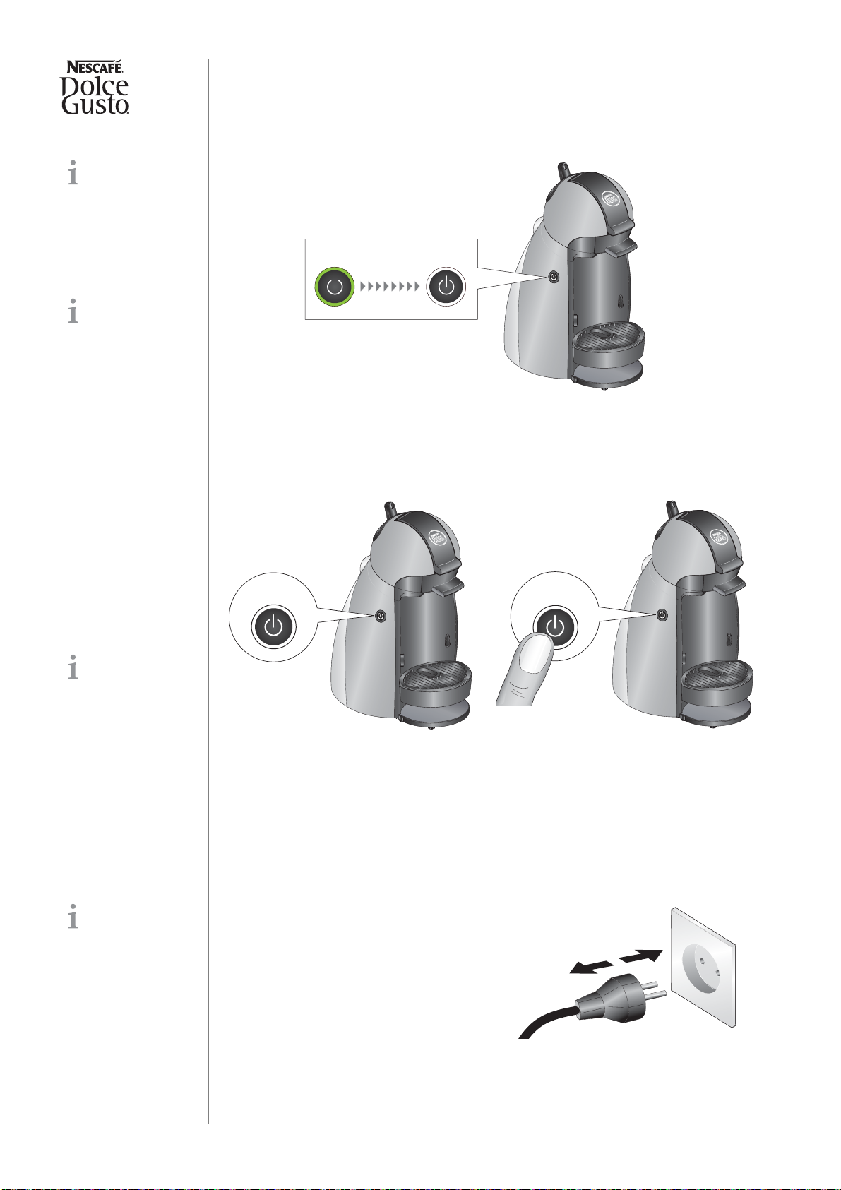
Economy mode (auto shut-off function)
After 5 minutes without operation, the machine switches itself OFF automatically.
To resume operation simply press power button.
Disable auto shut-off function
Aftertheautoshut-offfunction isdisabled themachinewillstayONwhenthepowerbutton
is pressed next time. To turn OFF the machine simply press the power button again.
Restore auto shut-off function
This feature helps
to save electricity by
reducing the amount of
power the machine
draws while it is not in
use and helps protect the
life of the machine.
For longer periods
of standstill
(vacation etc.):
• Plug out power cord.
• Empty water tank.
5 min
ON OFF
Ignore the light sig-
nals and wait until
the power button is no
longer illuminated.
1. Switch machine OFF. 2. Press and hold the power button for
about 30 seconds until the machine
turns OFF again.
OFF
~ 30 sec
A power failure can
restore the auto
shut-off function
accidently. 1. Unplug the machine to restore the
auto shut-off function.
13
Service manual
OPERATING
Empty fluid system for shipping
For shipping a
machine, it is
important to empty the
fluid system.
The machine will
not work without
inserted capsule holder.
Prolonged dry-
running can dam-
age the pump.
1. Empty water tank and drip tray. 2. Check that capsule holder is empty.
3. Reinstall capsule holder.
4. Set selection lever at position "cold
water". Let water run through for
approx. 5 sec.
5. Set selection lever at position "hot
water". Let water run through for
approx. 5 sec.
6. Setselectionlever at middleposition.
7. Remove and empty jug. 13. Clean machine and all accessories.
14. Send machine back with capsule
holder and all provided accessories.
~ 5 sec.
~ 5 sec.
STOP
14

Service manual
TROUBLESHOOTING
TROUBLESHOOTING
Checklist
The checklist enables you to rapidly locate faults on the machine and to initiate appropriate repair action.
Follow the check procedure. Repair any faults found and check if the machine is operating perfectly.
Check
procedure Symptoms Action / repair work Further action /
repair work
1 Check general
condition of machine
with
accessoriesand
look for visible
damage
1.1 Parts of housing are
broken or damaged (e.g.snap
connections or latches)
YES - Replace parts if necessary
NO - Go to point 1.2 —
1.2 Accessories are broken or
damaged
YES - Replace all broken or
damaged accessories
NO - Go to point 1.3 —
1.3 Shaky extraction head YES - Fasten 2 screws on extrac-
tion head
NO - Go to point 1.4 —
1.4 Power cord is damaged YES - Replace power cord
NO - Go to point 2 —
2 Check mechanical
elements
2.1 Capsule holder inserts
correctly into the extraction
head?
YES - Go to point 2.2
NO - Replace capsule holder NO - Check injector plate
2.2 Capsule holder magnetic
at all (right corner at back-
side)?
YES - Go to point 2.3
NO - Replace capsule holder. —
2.3 Magnet on backside of
capsule holder: Epoxy resin
cover cracked or brittle?
YES - Replace capsule holder
NO - Go to point 2.4 —
2.4 Drip tray inserts correctly
in all 3 levels?
YES - Go to point 2.5
NO - Check if drip tray is deformed
or damaged, replace if necessary. —
2.5 Damaged / broken locking
handle or selection lever?
YES - replace extraction head if
necessary
NO - Go to point 2.6
—
2.6 Selection of hot or cold is
possiblewhenextractionhead
is opened?
YES - Replace the extraction head
NO - Go to point 2.7 —
2.7 Locking handle can be
pulled up while making a
beverage?
YES - Replace the extraction head
NO - Go to point 3 —
3 Fill water tank
3.1 Water tank is leaking on
transport YES - Replace water tank
NO - Go to point 3.2 —
3.2Watertankisleakingwhen
it is inserted in the machine
YES - b) Try new water tank and
check if it is still leaking
NO - Go to point 4
YES - Replace water tank
connector
NO - Replace old water tank
15
Service manual
TROUBLESHOOTING
4 Plug into mains
and switch ON
machine
4.1 Machine (with capsule
holder inserted) is not working
- no function
YES - a) Check if power cord is
functional YES - Go to point b)
NO - Replace it
YES - b) Check if all electrical
connectors are connected
YES - Go to point c)
NO - Connect them
YES - c) Check if thermoblock’s
thermal cutoff fuses (133 °C) are
defective
YES - Replace power cord and
electronic mainboard. If neces-
sary replace also the ther-
moblock.
NO - Go to point d)
YES - d) Check if power button and
indicator (LED) is functional
YES - Go to point e)
NO - Replace power button
assembly. If
necessary replace electronic
mainboard also
YES - e) Check if reed contact is
functional
YES - Go to point f)
NO - Replace extraction head
YES-f)Checkif pumpis working at
position "cold water" YES - Go to point g)
NO - Go to point h)
YES - g) Check if pump is working
at position "hot water"
YES - Go to point 4.3
NO-Replacetheextractionhead
(valve switch might be broken).
If still not working,
replace also electronic main-
board.
YES - h) Check if pump's thermal
cut off fuse (98 °C) is defective
YES - Replace pump
NO - Replace pump
or electronic mainboard
or extraction head
4.2Indicator(LED)flashesred
3 times a second (error mode)
YES - a) Check if NTC temperature
sensor is functional
NO - Replace NTC temperature
sensor
YES - Go to point b)
YES - b) Check if electrical wires
are functional
NO - Go to point 4.3
YES - Replace electronic main-
board
NO - Replace defective wire(s)
4.3 Machine is working
without capsule holder YES - Replace the extraction head
NO - Go to point 4.4 —
4.4 Machine is hissing if selec-
tion lever is in middle position YES - Replace the extraction head
NO - Go to point 5 —
Check
procedure Symptoms Action / repair work Further action /
repair work
16

Service manual
TROUBLESHOOTING
5 Checks while
preparing a
beverage
5.1 No extraction possible (no
water at coffee outlet)
YES - a) Water tank is empty? YES - Fill water tank
NO - Go to point b)
YES - b) Water tank is correctly
inserted? YES - Go to point c)
NO - Insert water tank correctly
YES - c) Filter in water tank
connector is blocked or not in right
position?
YES - Clean filter or replace
water tank connector if neces-
sary
NO - Go to point d)
YES - d) Fluid system is empty?
YES - Prime fluid system without
a capsule: Set selection lever at
position cold and hot water for
about 10 sec successively.
NO - Go to point e)
YES - e) Fluid system is blocked by
scale?
YES - Descale the fluid system
NO - Go to point f)
YES- f) Injector is stillcloggedafter
descaling?
YES - Deblock injector with
cleaning needle or replace
injector plate
NO - Replace extraction head
5.2 Hot water temperature is
too low (less than 70 °C /
158 °F)
YES - a) Check if NTC temperature
sensor is functional
NO - Change NTC temperature
sensor
YES - Go to point b)
YES - b) Fluid system is scaled?
YES - Descale fluid system
NO - Replace electronic main-
board
YES - c) Valve malfunction? YES - Replace extraction head
NO - Go to point d)
YES - d) Flow rate of pump out of
range?
YES - Replace pump
NO - Go to point 5.3
5.3 Hot water temperature is
too high (more than 95 °C /
203 °F)
YES - a) Check if NTC temperature
sensor is functional
NO - Change NTC temperature
sensor
YES - Go to point b)
YES - b) Fluid system is scaled? YES - Descale fluid system
NO - Go to point 5.5
YES - d) Flow rate of pump is out of
range?
YES - Replace pump
NO - Go to point 5.4
5.4 Cold water temperature
too high (5 °C / 41 °F more
than water tank temperature)
YES - Valve malfunction?
NO - Go to point 5.5
YES - Replace extraction head
NO - Go to point 5.6
5.5 Selection lever does not
remainatposition"cold water"
or "hot water"
YES - Replace extraction head
NO - Go to point 5.6 —
5.6 The capsule does not fall
out of the capsule holder
YES - Check capsule and capsule
holder for deformations
NO - Go to point 6
YES - Replace capsule holder if
necessary
Check
procedure Symptoms Action / repair work Further action /
repair work
17

Service manual
TROUBLESHOOTING
6 Check for leaks
and/or flow rate
while preparing a
beverage
6.1 Leakage at extraction
head
YES - a) Capsule has multiple
perforations?
NO - Go to point 6.2
YES - Perforate capsule only
once, see user manual
NO - Replace extraction head
6.2 Water underneath the
machine YES - Defective pressure hoses?
NO - Go to point 6.3
YES - Replace defective pres-
sure hoses with clips
NO - Go to point 6.4
6.3 Flow rate out of range
YES - a) Fluid system is scaled? YES - Descale the fluid system
NO - Go to point b)
YES - b) Injector plate is blocked?
YES - Deblock injector with
cleaning needle
and descale again
NO - Go to point c)
YES - c) Filter of water tank
connector is blocked?
YES - Clean filter or replace
water tank connector if neces-
sary
NO - Replace pump
7 Check for loud
noises or vibrations
7.1 Check vibrations while
putting a plastic beaker on the
drip grid
YES - Coffee machine or plastic
beaker is moving around
YES - a) Check if drip tray and
drip grid are inserted correctly,
set it right if necessary
NO - Go to point b)
YES - b) Check if rubber feet are
missing, replace if necessary
NO - Go to point c)
YES - d) Pump is not firm in its
support, replace it
NO - Go to point c)
7.2 Check vibrations on the
water tank (water is waving) YES - Water tank is vibrating on the
machine?
YES - Pump is not firm in its
support, replace it
NO - Go to point 8
8 Perform final tests
9 Perform final
cleaning
Check
procedure Symptoms Action / repair work Further action /
repair work
18
Service manual
REPAIR
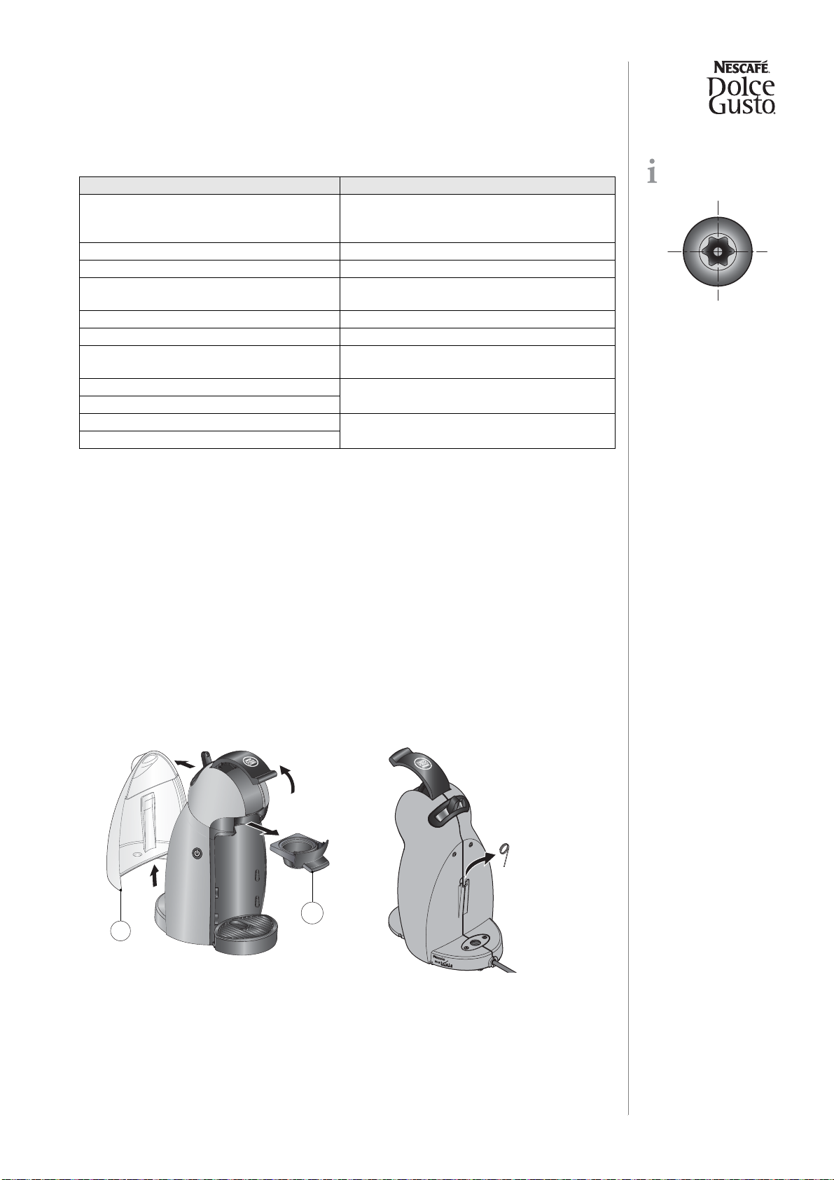
Tools and repair accessories
With the following tools, all described disassembly and repair work can be done:
Repair work without disassembling the machine
Without disassembling the machine, you can clean, replace or repair the following parts:
• Water tank (pos. 6)
• Capsule holder (pos. 17)
• Injector plate (pos. 19)
• Drip tray (pos. 13) and drip grid (pos. 14)
Cleaning or replacing injector plate, deblocking of injector
Solid residues in the water circuit can block the injector completely. An example is the
development of calcium particles if the machine is not descaled periodically. Therefore
this error appears during descaling frequently.
A pin-torx screw
head looks like this:
Tools Applications
Torx screwdriver for security screws,
Pin-TX 10
Fastening screws for
- extraction head
- side panels / water tank connector
Phillips screwdriver no. 1 Fastening screw of fuse holder on thermoblock.
Screwdriver with blade width 4 mm To open latches and snap connections
Flat nose pliers Flat receptacles, hose clips, filter element of
water tank connector
Fork wrench no. 12 Adjustable pump connector
Cutter (stanley knife) Cut new pressure hoses to length.
Cutting pliers To cut cable ties on pressure hoses and H-
connector
Small hammer Clamp spring (NTC temperature sensor)
Piercer
Pointed pliers NTC temperature sensor
Heat conducting paste
1. Remove water tank (pos. 3).
2. Remove capsule holder (pos. 17). 3. Switch off and unplug machine.
4. Take cleaning needle out of support.
3
17
19
Service manual
REPAIR
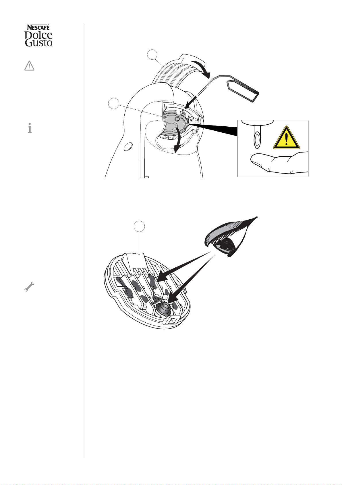
5. Close locking handle (pos. 2).
6. Release latch by pressing a suitable pin (dia. 1.8 mm max. e.g. a paper clip)
through hole and remove injector plate (pos. 19) by pulling it down.
7. Examine upper side of injector plate (pos. 19).
8. Clean interior space of sealing ring with a toothpick etc.
Danger of injury -
sharp pointed
injector!
The extraction
head is adjusted to a
specific injector plate
(pos. 19). Therefore do
not mix up different
injector plates acciden-
tally.
19
2
If upper side of
injector plate is wet
and badly soiled, the
sealing ring is defect. In
that case replace injector
plate.
19
20
This manual suits for next models
1
Table of contents
Other SEB Coffee Maker manuals


Popular Coffee Maker manuals by other brands

Slayer
Slayer Professional Series user manual

Ninja
Ninja CE200C Series owner's guide

Franke
Franke A1000 Original operating instructions

Jura
Jura Impressa J6 Quick reference guide

Grindmaster
Grindmaster Grind'n Brew-10H Operation and Operation and instruction manual

TREVIDEA
TREVIDEA G3 FERRARI TIFFANY user manual


