Siemens Industry, Inc. Siemens Building Technologies, Ltd.
Building Technologies Division Fire Safety & Security Products
Florham Park, NJ 2 Kenview Boulevard
Brampton, Ontario L6T 5E4 Canada
P/N 315-049308-6 (v12-14-09)
INSTALLATION INSTRUCTIONS
Model FS-RU2 Serial Relay Unit
Model FS-RE8 Serial Relay Extender
The FS-RU2 Serial Relay Unit is an optional accessory for the FS-250 and FS-250C Fire Alarm System
Control Panels. The FS-RU2 includes a processor board and a relay board. The processor board receives
commands from the control unit for activating the relays and transmits supervision and control functions to
the control unit. The processor board can control up to 3 relay boards. Each relay board provides 8 relays
with Form C contacts. The control unit can address up to 8 Serial Relay Units and/or Serial Annunciator
Units. Auxiliary power supplies will be required to power units beyond the control unit capability.
FS-RU2 PARTS SUPPLIED
1 Processor Board Assembly
1 Relay Board Assembly
1 34 pin Cable Assembly, 3 1/2”
1 PCB Track, 14 1/2”
1 10 pin Cable Assembly, 6”
1 Screwdriver
3 Keps Nut, #6-32
1 Instruction Sheet
FS-RE8 PARTS SUPPLIED
1 Relay Board Assembly
1 34 pin Cable Assembly, 15”
1 34 pin Cable Assembly, 3 1/2”
1 PCB Track, 14 1/2”
3 Keps Nut, #6-32
1 Instruction Sheet
P6 SW-1 S1
FS-RU2 DIMENSIONS
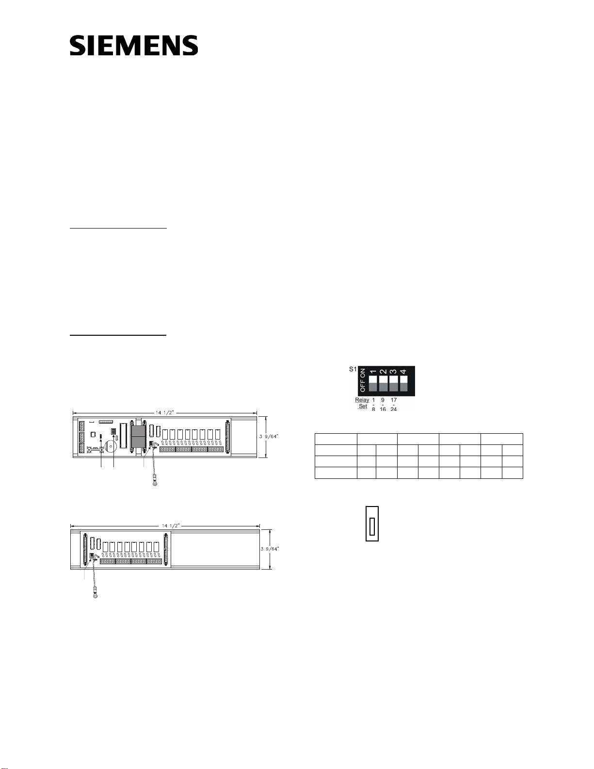
S1
FS-RE8 DIMENSIONS
Step 1.) Installation is to be done by qualified personnel
who have thoroughly read and understood this
instruction sheet.
Step 2.) Disconnect BATTERY and AC prior to working on
equipment.
Step 3.) Mount enclosure that is UL Listed for Fire
Protective Signaling Use as required in a dry
protected environment.
Step 4.) Attach conduit and run wires as required in a dry
protected environment.
Step 5.) Set processor board dip switch (SW1) for proper
remote address (See FS-RU Address Setting).
Step 6.) Set each relay board dip switch (S1) for proper
relay set number on the relay board (FS-RE8).
NOTE: Relays are numbered from left to right:
Relay Set TB1 TB2 TB3 TB4
(1-8) 1 2 3 4 5 6 7 8
(9-16) 9 10 11 12 13 14 15 16
(17-24) 17 18 19 20 21 22 23 24
Step 7.) Set jumper P6 for desired buzzer operation.
P6 – BUZZER ACTIVATION
•REMOTE
•
•LOCAL (Processor Board Buzzer)
NOTE: When “Local” is selected, the buzzer follows the sounder
on the panel. When “Remote” is selected, the local
buzzer does not activate, but the “Remote Buzzer Output”
pin of P2 follows the sounder on the panel.
Step 8.) Mount PCB Track(s) using #6-32 keps nuts and
snap in PCB assemblies.
Step 9. Plug in the cable assembly(s) to the PCB
assemblies as required.
Step 10. Connect ground wire(s) to chassis ground using
#6-32 keps nut(s).
Step 11.) Connect IN wires from fire alarm system control
unit or previous remote as required.
Step 12.) Connect OUT wires to next remote or 120 ohm
E.O.L. Resistor Assembly (P/N 140-050008-1), if
last remote.


