manuals.online logo
Brands
  1. Home
  2. •
  3. Brands
  4. •
  5. Allen-Bradley
  6. •
  7. Relay
  8. •
  9. Allen-Bradley Guardmaster 440R-S35011 User manual

Allen-Bradley Guardmaster 440R-S35011 User manual

Installation Instructions
Original Instructions
Back EMF Monitoring Relay Module
Catalog Numbers
440R-S35011, 440R-S35012, 440R-S35013,440R-S35014, 440R-S35015, 440R-S35016
Description
The Allen-Bradley Guardmaster® MSR55P back EMF modules are
suitable to monitor the standstill of all electric motors that generate a
remanence voltage while coasting to stop.
The MSR55P standstill module is connected to the motor terminals
and measures the induced back EMF voltage. Two redundant measuring
channels are used (L2-L1 and L3-L1). If the back EMF voltage drops to
0V simultaneously in both channels, it indicates standstill and the
output relay is energized.
The voltage threshold that indicates a standstill on the MSR55P
module is adjustable. This standstill allows the unit to work with
different types of motors in various applications. The standstill time Ts
(time delay between detection and energizing of the relay) is also
adjustable.
The MSR55P standstill module detects a broken wire on the measuring
inputs L1/L2/L3. If a broken wire is detected, the relay outputs go into
safe state (as with running motor).
Features
• Safe standstill detection on three-phase and single-phase motors
• Performance Level is PLe
• Category 4 to EN ISO13849-1: 2008
• Safety integrity level (SIL) 3 to IEC/EN 61508
• SIL Claim Limit (SIL CL) 3 to IEC/EN 62061
• No external sensors necessary
• Standstill detection independent of direction
• Broken wire detection
• Three N.O. redundant voltage-free safety contacts and one
redundant N.C. monitoring contact for up to 250V AC
• Two semiconductor status outputs
• Monitors motor voltage up to 690V AC
• Adjustable voltage setting
• Adjustable standstill time delay
• LED indicators for standstill, event of line breakage and
operation voltage
• Suitable for operation with inverters
• Removable screw terminals
Figure 1 - Overview of Key Features
DIN Rail Mounting and Removal
MSR55P standstill module safety relays mount onto 35 mm (1.4 in.)
DIN rails.
Spacing
MSR55P standstill module safety relays can be mounted directly next to
other MSR and GSR safety relays.
Maintain a space of 50.8 mm (2 in.) above, below, and in front of the
relay for adequate ventilation or provide forced (fan) cooling.
Removable Terminals
MSR55P standstill module safety relays have removable terminals to
ease wiring and replacement.
IMPORTANT Save these instructions for future use.
1. Insert the tip of a small
screwdriver into the
slot near the terminal
screws.
2. To unlock the terminal
block, rotate the
screwdriver.
Three indicators
for status and
diagnostics
Removable terminal
blocks
Standstill voltage setting
Standstill time delay setting
2Rockwell Automation Publication 440R-IN081B-EN-P - February 2020
Back EMF Monitoring Relay Module
Excessive Heat Prevention
For most applications, normal convective cooling keeps the relay within
the specified operating range. Verify that the specified temperature
range is maintained. Usually, proper spacing of components within an
enclosure is sufficient for heat dissipation.
Additional provisions are necessary to cool equipment when high
ambient temperatures are encountered. Do not bring in unfiltered
outside air. Place the MSR55P standstill module in an enclosure to help
protect it from a corrosive atmosphere. Harmful contaminants or dirt
could damage components or cause improper operation. In extreme
cases, air conditioning helps protect against heat buildup within the
enclosure.
Wiring Requirements and Recommendation
• Allow for at least 50 mm (2 in.) between I/O wire ducts or
terminal strips and the relay.
• Route incoming power to the relay by a path separate from the
device wiring. Where paths must cross, their intersection must
be perpendicular.
• Do not run signal or communications wiring and power wiring
in the same conduit. Route wires with different signal
characteristics by separate paths.
• Separate wiring by signal type. Bundle wiring with similar
electrical characteristics together.
• Separate input wiring from output wiring.
• Label wiring to all devices in the system. Use tape, shrink-
tubing, or other more dependable means to label wire. Use
colored insulation as well to identify wiring by signal
characteristics. For example, use blue for DC wiring and red for
AC wiring.
Enclosure Requirements
Install the MSR55P standstill module in an enclosure that meets the
environmental requirements of Pollution Degree 2, where only
non-conductive pollution occurs except that occasionally a temporary
conductivity caused by condensation is to be expected.
Relay Face and Terminal Identification
Table 1 - Terminal Assignments and Functions
ATTENTION: Before you install and wire any device, disconnect
power to the system.
Calculate the maximum possible current in each power and
common wire. Observe all electrical codes that dictate the
maximum current allowable for each wire size. Current above the
maximum rating causes wiring to overheat, which can cause
damage.
Terminal Function
A1(+)…A2(-) Power supply
L1/L2/L3 Motor connections
11/12 Voltage-free redundant monitoring (non-safety) contacts (N.C.)
23/24, 33/34, 43/44 Voltage-free redundant safety contacts (N.O.)
53/54 Voltage-free monitoring (auxiliary) contact (N.O.)
X1/X2 Connection for feedback circuit
X3/X2 Reset for fault conditions.
A3(+)…A4(-) Power supply for semiconductor outputs
ON Non-safety semiconductor output indicates that safety outputs are ON.
ERR Non-safety semiconductor output indicates fault condition.
ATTENTION: The outputs 53…54, ON and ERR are only
monitoring outputs and must not be used in safety circuits.
53 54 L1 L2 L3
X1 X2 X3 11 23 33 43
12 24 34 44
A3 A4 ON ERR A1 A2
OUT
ERR
PWR
53 54 L1 L2 L3
X1 X2 X3 11 23 33 43
12 24 34 44
A3 A4 ON ERR A1 A2
OUT
ERR
PWR
.2 .4
.7
MSR55P
1
1.5
23
4
.5
.3
.2 .4
.7
ts
Vm
1
1.5
2
6
.5
.3
24
7
MSR55P
10
15
0302
40
5
3
.2 .5
1
ts
x10mVm
1.5
2
4
.7
.3
63
3
3534113233
4544214243
3534113233
4544214243
43
Rockwell Automation Publication 440R-IN081B-EN-P - February 2020 3
Back EMF Monitoring Relay Module
Connect Power Supply
Power for the MSR55P standstill module safety relay depends on the
model. The primary power supply is connected to terminals A1 and A2.
An auxiliary (12…30V DC only) supply voltage can be connected to
terminals A3/A4 to provide semiconductor diagnostics.
Depending on the model, the primary supply can be 24V DC, 115V
AC, or 230V AC. When an AC supply is used, both 50 Hz and 60 Hz
are acceptable.
When powering with 24V DC in the European Union, the DC supply
must have a Protective Extra-Low Voltage (PELV) rating. When
powering with 24V DC in the United States, the DC supply must have
both a PELV rating as well as an NEC Class 2 rating. Many of our
Bulletin 1606 power supplies are PELV and Class 2 compliant.
Power to A1/A2 is required to operate the MSR55P standstill module
safety relay. Power to A3/A4 is only necessary if the solid-state auxiliary
status signals (ON and ERR) are used.
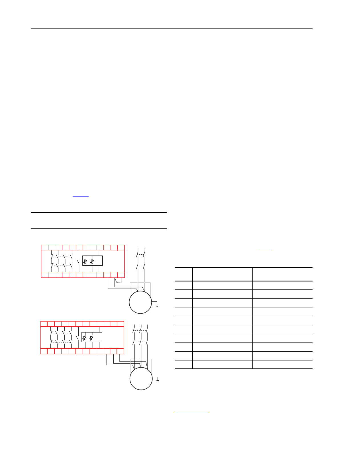
Motor Winding Inputs
The motor windings are connected to terminals L1, L2, and L3. The
connections must be made directly at the motor with no electrical
devices (like transformers and contactors) between the motor and the
MSR55P safety relay. Figure 3 shows wiring for a single-phase, DC, and
a three-phase motor.
Figure 2 - Motor Connections
Surge Suppressors
Because of the potentially high current surges that occur when switching
inductive load devices, such as motor starters and solenoids, the use of
surge suppression is required. Adding a suppression device prolongs the
life of the relay outputs and reduces the effects of voltage transients and
electrical noise from radiating into adjacent systems.
Since this is a safety-related system, the surge suppression device must
connected across the load device. The surge suppression device must not
be connected across the MSR55P safety relay contacts.
For outputs that use 24V DC, we recommend 1N4001 (50V reverse
voltage) to 1N4007 (1000V reverse voltage) diodes for surge
suppression. The diode must be connected as close as possible to the
load coil.
For outputs that use 120V AC or 240V AC, we recommend metal oxide
varistors.
Configuration
The configuration of MSR55P safety relays is accomplished by
adjusting the two switches on the front face. Each switch control knob
rotates two potentiometers. The recommended practice is to set the
switches to the minimum setting initially, and then adjust them as
necessary to reduce nuisance tripping while maintaining a safe
application.
V
m
- Monitoring Voltage
The trip voltage of the back EMF is adjusted by the 10-position Vm
potentiometer. When the back EMF drops below the voltage level, the
MSR55P standstill module safety relay begins the delay timer. After the
timer expires, the outputs are de-energized. Table 2 shows the settings of
each of the catalog numbers.
Table 2 - Vm- Monitoring Voltage Settings
t
s
- Time Delay
When the back EMF of the motor drops below the Vm voltage setting,
the standstill delay timer starts. The delay time is set by the 10-position
ts potentiometer. During the timing cycle, the OUT indicator flashes.
Table 3 on pa g e 4 shows the delay time for each setting. After the delay
expires, the outputs are energized.
IMPORTANT The three connections create two safety monitor channels. L1
is common to the two channels, which are L2 and L3.
L1 L2 L3
M
K1
K2
A2
X1 X2
1L2L3L
X3
34 44
A1 A3113233
2142ON
ERR A454
43 53
L1 N
M
K1
K2
A2
X1 X2
1L2L3L
X3
34 44
A1 A3113233
2142ON
ERR A454
43 53
Single-phase and DC Motor
Three-phase
Position 440R-S35014, 440R-S35015,
440R-S35016 [Volts]
440R-S35011, 440R-S35012,
440R-S35013 [x10mV]
10.2 2
20.3 3
30.4 4
40.5 5
50.7 7
61.0 10
71.5 15
82 20
93 30
10 4 40
Allen-Bradley, Guardmaster, Rockwell Automation, and Rockwell Software are trademarks of Rockwell Automation, Inc.
Trademarks not belonging to Rockwell Automation are property of their respective companies.
Rockwell Otomasyon Ticaret A.Ş., Kar Plaza İş Merkezi E Blok Kat:6 34752 İçerenköy, İstanbul, Tel: +90 (216) 5698400
Rockwell Automation maintains current product environmental information on its website at http://www.rockwellautomation.com/rockwellautomation/about-us/sustainability-ethics/product-environmental-compliance.page.
Publication 440R-IN081B-EN-P - February 2020 10005051946 Ver 01
Supersedes Publication 440R-IN081A-EN-P - June 2019 Copyright © 2020 Rockwell Automation, Inc. All rights reserved. Printed in the U.S.A.
Table 3 - TsDelay Time Settings
Status Indicators and Diagnostics
Three indicators on the front provide the operating status of the
MSR55P standstill module safety relay. Tab le 4 describes the state of
each indicator.
Table 4 - Status Indicators
MSR55P standstill module safety relays include a number of facilities to
detect faults that could influence the safety function of the module.
Checks are conducted on power- up of the unit and in cycles during
normal operation. If a fault occurs, the output relays switch off. The
fault state is indicated with the ERR indicator, the PWR indicator, and
the semiconductor output ERR.
With safety relevant failures, your MSR55P standstill module safety
relay differentiates between external failures (broken wire/offset,
simultaneity failure, or feedback circuit failure) and internal failures.
Broken wire/offset failures and feedback circuit failures can be restored
by using manual reset. They can also be reset automatically after
removing the fault by placing a jumper from terminal X2 toX3.
The number of times the ERR status indicator blinks communicates
diagnostics. When multiple faults exist simultaneously, the ERR
indicator shows the highest priority. After the highest priority fault is
corrected, the ERR shows the next highest priority fault.
Figure 3 - ERR Flashing Codes
Rockwell Automation Support
For technical support, visit
http://www.rockwellautomation.com/support/overview.page.
Waste Electrical and Electronic Equipment (WEEE)
Position Delay Time [seconds]
10.2
20.3
30.5
40.7
51.0
61.5
72.0
83.0
94.0
10 6.0
Indicator State Description
PWR
Off No power to A1
Green Normal operation
Red Internal Fault
OUT
Green Safety outputs are energized
Flashing green In timing cycle
Flashing orange Intermittent crossing of the Vmtrip point
Orange Safety outputs are de-energized
Off Code 1 or code 5 error is present
ERR
Off No faults exist; normal operation
Flashing red Fault is present (see Figure 3)
At the end of life, this equipment should be collected separately
from any unsorted municipal waste.
Flashing codes of the ERR indicator in sequence of priority
t
2 s0 s 4 s
1) Undervoltage at PWR
2) Wire-break/offset on L1 or L2
3) Wire-break/offset on L3
4) Failure in feedback circuit X1-X2
5) Simultaneity failure signal L2/L3
6) Potentiometer error Vm
7) Potentiometer error ts

This manual suits for next models

5

Other Allen-Bradley Relay manuals

Allen-Bradley Guardmaster 440C-CR30 User manual

Allen-Bradley

Allen-Bradley Guardmaster 440C-CR30 User manual

Allen-Bradley Bulletin 700S-CF User manual

Allen-Bradley

Allen-Bradley Bulletin 700S-CF User manual

Allen-Bradley 193-EF1A User manual

Allen-Bradley

Allen-Bradley 193-EF1A User manual

Allen-Bradley CEFB1-11 User manual

Allen-Bradley

Allen-Bradley CEFB1-11 User manual

Allen-Bradley 140G-N User manual

Allen-Bradley

Allen-Bradley 140G-N User manual

Allen-Bradley 140G Series User manual

Allen-Bradley

Allen-Bradley 140G Series User manual

Allen-Bradley 140G Series User manual

Allen-Bradley

Allen-Bradley 140G Series User manual

Allen-Bradley E100 User manual

Allen-Bradley

Allen-Bradley E100 User manual

Allen-Bradley Guardmaster MINOTAUR MSR121RT User manual

Allen-Bradley

Allen-Bradley Guardmaster MINOTAUR MSR121RT User manual

Allen-Bradley E200 User manual

Allen-Bradley

Allen-Bradley E200 User manual

Allen-Bradley Guardmaster 440C-CR30-22BBB Quick start guide

Allen-Bradley

Allen-Bradley Guardmaster 440C-CR30-22BBB Quick start guide

Allen-Bradley Guardmaster GLP User manual

Allen-Bradley

Allen-Bradley Guardmaster GLP User manual

Allen-Bradley PowerFlex 3P-FCOVPD-B-FA User manual

Allen-Bradley

Allen-Bradley PowerFlex 3P-FCOVPD-B-FA User manual

Allen-Bradley 193 E1 PLUS Series User guide

Allen-Bradley

Allen-Bradley 193 E1 PLUS Series User guide

Allen-Bradley E300 User manual

Allen-Bradley

Allen-Bradley E300 User manual

Allen-Bradley Guardmaster User manual

Allen-Bradley

Allen-Bradley Guardmaster User manual

Allen-Bradley 193-EEGF E1 PLUS User guide

Allen-Bradley

Allen-Bradley 193-EEGF E1 PLUS User guide

Allen-Bradley Guard master Minotaur MSR312P User manual

Allen-Bradley

Allen-Bradley Guard master Minotaur MSR312P User manual

Allen-Bradley MINOTAUR MSR144RTP User manual

Allen-Bradley

Allen-Bradley MINOTAUR MSR144RTP User manual

Allen-Bradley 140G Series User manual

Allen-Bradley

Allen-Bradley 140G Series User manual

Allen-Bradley MSR127 User manual

Allen-Bradley

Allen-Bradley MSR127 User manual

Allen-Bradley 140MG-H Guide

Allen-Bradley

Allen-Bradley 140MG-H Guide

Allen-Bradley GUARDMASTER MINOTAURMSR125H User manual

Allen-Bradley

Allen-Bradley GUARDMASTER MINOTAURMSR125H User manual

Popular Relay manuals by other brands

Dossena RECA/E8 instructions

Dossena

Dossena RECA/E8 instructions

Real-El VR-101F user manual

Real-El

Real-El VR-101F user manual

Omron MY4H datasheet

Omron

Omron MY4H datasheet

LEGRAND Celiane 673 91 installation instructions

LEGRAND

LEGRAND Celiane 673 91 installation instructions

Pilz PNOZ s60 operating manual

Pilz

Pilz PNOZ s60 operating manual

Intelligent Appliance IA Daisy-chain Series user manual

Intelligent Appliance

Intelligent Appliance IA Daisy-chain Series user manual

Elko HRN-43 manual

Elko

Elko HRN-43 manual

Thytronic SIF5600 manual

Thytronic

Thytronic SIF5600 manual

Omron SR203M installation instructions

Omron

Omron SR203M installation instructions

GE C60 instruction manual

GE

GE C60 instruction manual

Viessmann 5227 Operation manual

Viessmann

Viessmann 5227 Operation manual

Basler BE1-DFPR instruction manual

Basler

Basler BE1-DFPR instruction manual

ABB CAP 501 Installation and commissioning manual

ABB

ABB CAP 501 Installation and commissioning manual

Leuze MSI-SR5B Original operating instructions

Leuze

Leuze MSI-SR5B Original operating instructions

EVA Logik ZW12 user manual

EVA Logik

EVA Logik ZW12 user manual

Circutor RGU-10C manual

Circutor

Circutor RGU-10C manual

FANOX SIA-B user manual

FANOX

FANOX SIA-B user manual

Chenzhu CZSR8801-8A4B user manual

Chenzhu

Chenzhu CZSR8801-8A4B user manual

manuals.online logo
manuals.online logoBrands
  • About & Mission
  • Contact us
  • Privacy Policy
  • Terms and Conditions

Copyright 2025 Manuals.Online. All Rights Reserved.