SEC 06906 User manual

06904 - 06906 - 06908 - 06909
SENSORI DI PARCHEGGIO
PARKING SENSORS
AVERTISSEUR DE RECUL
PARK-SENSOREN
SENSORES DE APARCAMIENTO
Istruzioni di montaggio
Installation instructions
Instructions de montage
Montageanleitung
Instrucciones para el montaje

2
3
I - Sono dispositivi elettronici studiati per facilitare le operazioni di parcheggio della vettura a bassa velocità.
Il sistema utilizza la tecnologia elettronica degli ULTRASUONI di terza generazione, basata sul principio della
riflessione delle onde sonore.
Un gruppo di sensori, installati sul veicolo, rivelano la presenza di eventuali ostacoli e ne segnalano la distanza
con un avvisatore acustico a 4 stadi. Con l’installazione del display 06911-912 (opzionale) è possibile, inoltre,
avere una segnalazione visiva della distanza e determinare il posizionamento dell’ostacolo rispetto alla vettura.
I sensori, di ridotte dimensioni e verniciabili, consentono un’installazione universale che si integra al meglio al
design delle strutture originali del veicolo.
GB - These electronic devices have been studied to facilitate the car-parking operations at low speed. They work
according to a third-generation ULTRASOUND technology, on the sound-waves reflection principle.
A group of sensors, installed on the car, reveals the presence of possible obstacles and signals their distance by
means of an acoustic signal coming at four different modulations.
With the aid of the display art. 6\911-912(optional), it is possible to have the obstacle distance and its exact posi-
tion, visualized with respect to the car. The sensors are of small dimensions, can be painted and are of universal
use. Their design perfectly matches the original car structures.
FR - Ces dispositifs électroniques ont été étudiés pour faciliter les opérations de stationnement à petite vitesse.
Le système utilise des ULTRASONS de troisième génération basés sur le principe de réflexion des ondes sono-
res. Un groupe de senseurs, installés sur le pare-chocs, relèvent la présence d’éventuels obstacles et en signa-
lent la distance au moyen d’un avertisseur acoustique à 4 stades de modulation.
Le display 6\911-912 permet de voir la distance de l’obstacle par rapport à la voiture et donc déterminer sa
position. Les senseurs sont de dimensions réduites et vernissable. Il peuvent être facilement installés sur tous
modèles de voiture s’intégrant parfaitement au dessin des différentes structures originales du véhicule.
D - Diese elektronischen Einrichtungen vereinfachen jedes langsam vorgenommene Parkmanöver. Das System
wird durch die Ultraschall-Technologie der 3. Generation gesteuert, die auf dem Prinzip der Schallwellen-Re-
flektierung basiert. Die Gruppe von Sensoren, die auf der Stossstange befestigt ist, hält Ausschau auf etwaige
Hindernisse und gibt gleichzeitig, anhand eines 4-stufig modulierten Hörsignals, Aufschluss über die Entfernung
des Hindernisses von der hinteren Stossstange.
Die Sensoren sind klein bemessen, ermöglichen nachtägliche Farbänderung und passen im Design universell zu
jeder Original-Wagenausstattung.
E - Son dispositivos electrónicos estudiados para facilitar las operaciones de estacionamiento del coche a baja
velocidad. El sistema utiliza la tecnología electrónica de los ultrasonidos de tercera generación que se basa
sobre el principio de las reflexiones de las ondas sonoras.
Un grupo de sensores instalados al vehículo revela la presencia de eventuales obstáculos y señala la distancia
con un beep de 4 niveles.
Con la instalación del display 6\911-912 (opcional) es posible además tener una señalización visiva de la distan-
cia y determinar la posición del obstáculo respecto a la del vehículo. Los sensores de reducidas dimensiones se
pueden pintar y consienten una instalación universal, y se integran perfectamente al diseño de las estructuras
de origen del vehículo.
DESCRIZIONE DESCRIPTION DESCRIPTION BESCHREIBUNG DESCRIPCIÓN
2
3
COMPONENTI PARTS COMPOSANTS KOMPONENTEN COMPONENTES
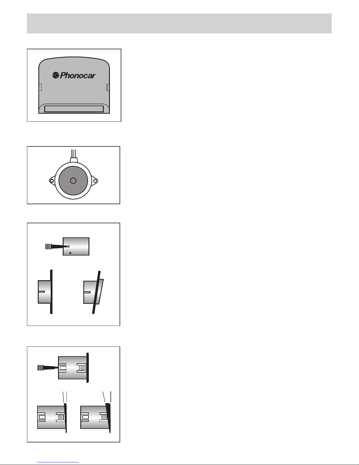
I- Collocare nel vano bagagli in uno spazio protetto da polvere e umidità.
GB - It has to be placed within the trunk, in a position protected from dust
and humidity.
FR - Placer dans le coffre, dans une position à l’abri de la poussière et de
l’humidité.
D - Diese Einheit muss im Kofferraum, an einer staub- bzw. wasserfreien
Stelle, montiert werden.
E - Esta unidad tiene que ser montada en el maletero, en un espacio
protegido, lejos del polvo y humedad.
UNITÁ CENTRALE - CENTRAL UNIT - UNITÉ CENTRALE - ZENTRAL-EINHEIT - UNIDAD CENTRAL
I- Collocare in una posizione che non ostacoli l'emissione sonora.
GB - Install in a position where the alarm-emission will not be obstacled.
FR - Placer dans une position favorable à l’émission du bruit sonore.
D - Die Installierungs-Position so wählen, dass das akustische Warnsignal
sich frei entfalten kann.
E - Instalar en una posición que no impida la emisión del sonido.
AVVISATORE ACUSTICO - ACOUSTIC SIGNAL DEVICE - AVERTISSEUR ACOUSTIQUE
AKUSTICHER SIGNALGEBER - SEÑALADOR ACUSTICO
SENSORI - SENSORS - SENSEUR - SENSOREN - SENSORES 06908 - 06909
SENSORI - SENSORS - SENSEUR - SENSOREN - SENSORES 06904 - 06906
I- Sistema composto da 4 sensori miniaturizzati ad ultrasuoni.
4 Supporti inclinati, 4 supporti piani verniciabili del colore della vettura.
GB - The system is composed of 4 miniaturized ultrasound-sensors, as well as
4 inclined adapters and 4 flat adapters, paintable to match colour of the car.
FR - Système constitué de 4 capteurs miniaturisés à ultrasons 4 supports
inclinés, 4 supports plats qui peuvent être peint par rapport à la couleur de la
voiture.
D - Das System besteht aus 4 Miniatur-Ultraschall-Sensoren. Mitgeliefert
werden 4 geneigte Adapter und 4 Flach-Adapter, die in der Farbe des Wagens
lackierbar sind.
E - Sistema compuesto por 4 sensores miniaturizados por ultrasonidos.
4 Soportes inclinados, 4 soportes planos que se pueden pintar del mismo
color del coche.
I- Sistema composto da 4 sensori miniaturizzati ad ultrasuoni.
8 Supporti inclinati, 4 supporti piani verniciabili del colore della vettura.
GB - A system consisting of 4 ultrasound miniaturized sensors.
8 inclined supports, 4 flat supports can be painted in the colour matching
the car.
FR - Il s’agit d’un jeu de 4 senseurs miniaturisés à ultrasons.
8 Supports inclinés, 4 supports plats vernissable dans la couleur de la voiture.
D - Das System besteht aus 4 Ultraschall-Miniatur-Sensoren.
8 Geneigte Adapter, 4 Flach-Adapter
Sie können nachträglich der Wagenfarbe angepasst werden.
E - Sistema compuesto por 4 sensores de ultrasonidos miniaturizados.
8 Soportes inclinados, 4 soportes planos que se pueden pintar del mismo
color del vehículo.
4 pcs
4 pcs
4 pcs4 pcs
4 pcs4 pcs
12°2°
4
5
INSTALLAZIONE INSTALLATION INSTALLATION EINBAU INSTALACIÓN
CONSTANT BEEP
8 BEEP
5 BEEP
3 BEEP
6 BEEP
4 BEEP
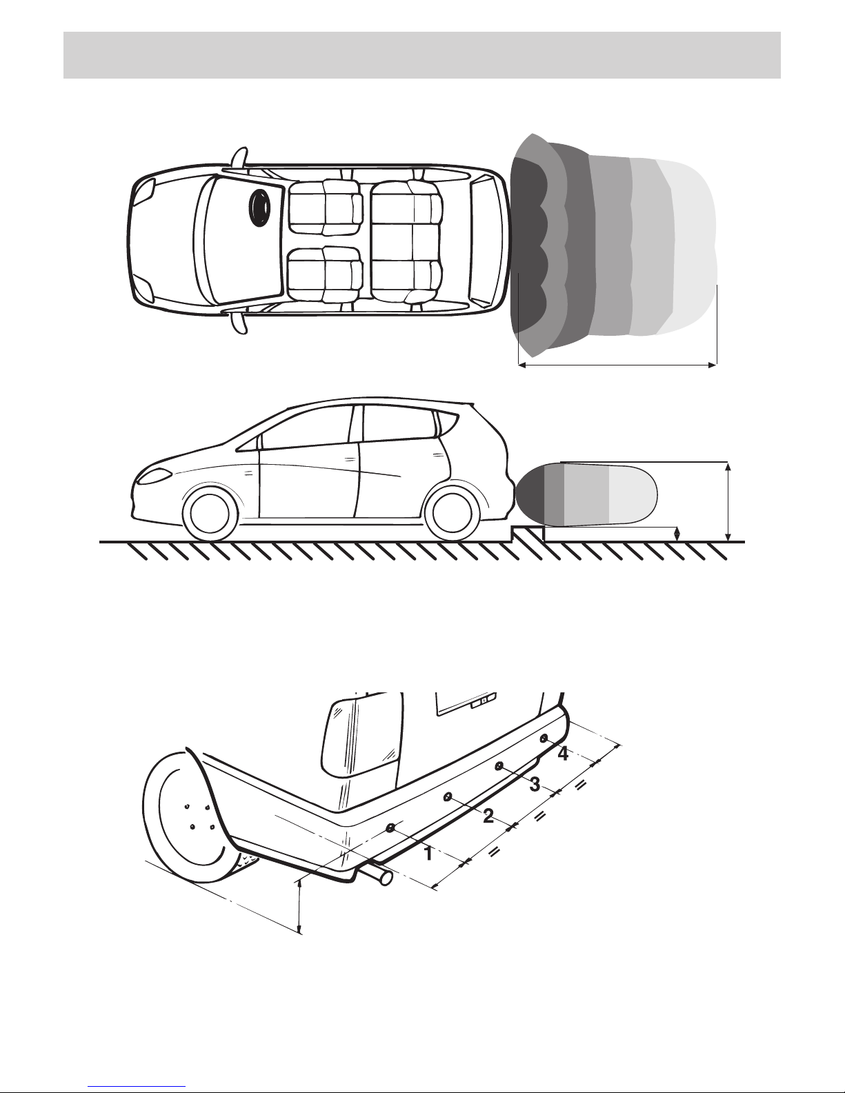
150 cm
10 cm
90 cm
06904 - 06908
45 cm. MIN.
60 cm. MAX.
10 cm. MIN.
25 cm. MAX.
10 cm. MIN.
25 cm. MAX.
4
5
INSTALLAZIONE INSTALLATION INSTALLATION EINBAU INSTALACIÓN
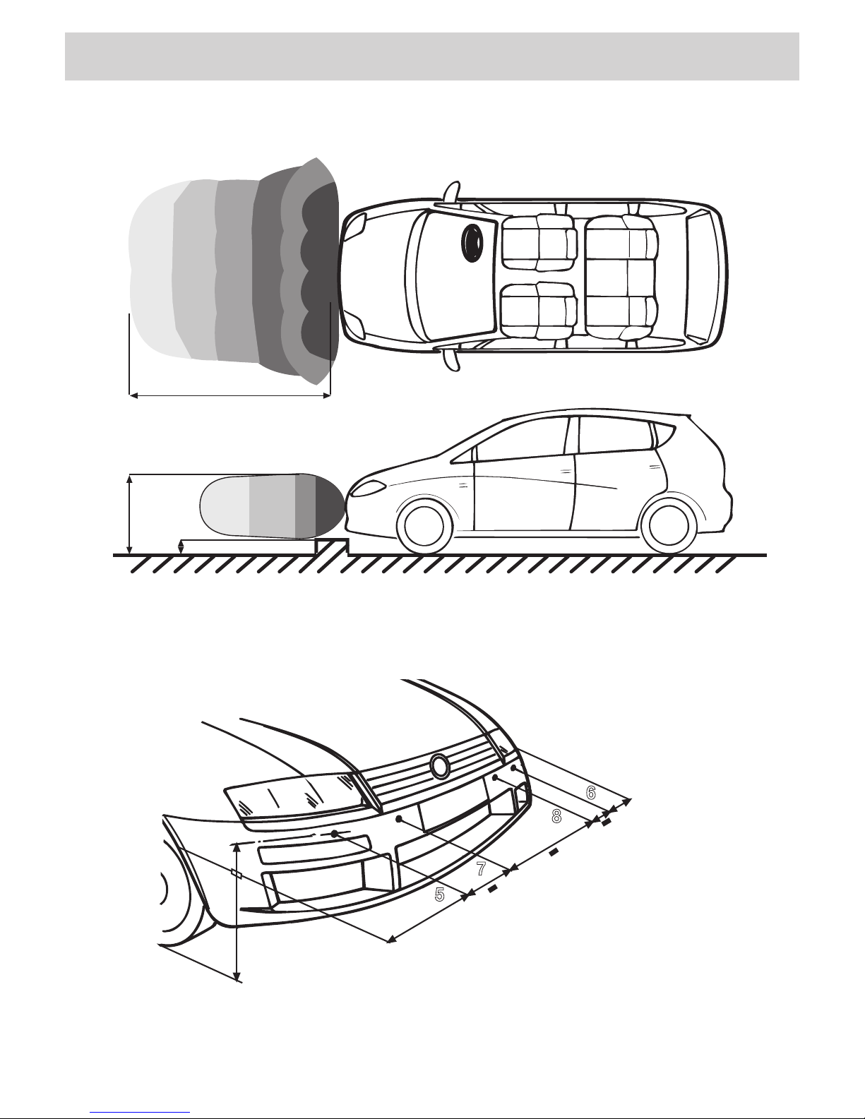
10 cm
90 cm
CONSTANT BEEP
8 BEEP
5 BEEP
3 BEEP
6 BEEP
4 BEEP
100 cm
06906 - 06909
45 cm. MIN.
60 cm. MAX.
10 cm. MIN.
25 cm. MAX.
10 cm. MIN.
25 cm. MAX.
5
7
8
6

6
7
FUNZIONI FUNCTIONS FONCTIONS FUNKTIONEN FUNCIONES
TIPOLOGIE D'INSTALLAZIONE • INSTALLATION-POSSIBILITIES • TYPES D’INSTALLATION
INSTALLATIONS-MÖGLICHKEITEN • TIPOLOGIAS DE INSTALACION
FORO
HOLE
Ø 17,2 mm
12°
FORO
HOLE
Ø 22,4 mm
12°
FORO
HOLE
Ø 22,4 mm
I- 1 Supporto inclinato (12°).
2 Supporto piano.
3 Involucro sensore.
4 Sensore.
5 Biadesivo.
6 Sensore montato sul supporto
• Si consiglia l’utilizzo del set di trancianti 89/947 • We recommend to use the Cutter-Set 89/947.
• Il est conseillé d’utiliser le set de fraises 89/947 • Wir empfehlen das Locher-Set 89/947 zu verwenden.
• Se aconseja la utilización del kit cortante 89/947
GB - 1 Iinclined Support (12°)
2 Flat Support
3 Sensor-Housing
4 Sensor
5 Bi-adhesive tape
6 Sensor installed on Support
FR -1 Support incliné (12°)
2 Support plat
3 Capsule en plastique du capteur
4 Capteur
5 Bi-adhésif
6 Capteur installé sur le support
D- 1 Geneigter Adapter (12°)
2 Flach-Adapter
3 Sensor-Halterung
4 Sensor
5 beidseitig klebende Unterlage
6 Sensor auf Adapter montiert
E- 1 Soporte inclinado (12°).
2 Soporte plano.
3 Involucro sensor.
4 Sensor.
5 Biadhesivo.
6 Sensor montado sobre el soporte
① ② ③ ④
⑤
⑥
INSTALLAZIONE INSTALLATION INSTALLATION EINBAU INSTALACIÓN
06904 - 06908
6
7
FUNZIONI FUNCTIONS FONCTIONS FUNKTIONEN FUNCIONES
TIPOLOGIE D'INSTALLAZIONE • INSTALLATION-POSSIBILITIES • TYPES D’INSTALLATION
INSTALLATIONS-MÖGLICHKEITEN • TIPOLOGIAS DE INSTALACION
I- 1 Supporto inclinato (12°/ 2°).
2 Supporto piano.
3 Sensore.
GB - 1 Iinclined Support (12°/ 2°)
2 Flat Support
3 Sensor
FR - 1 Support incliné (12°/ 2°)
2 Support plat
3 Capteur
D- 1 Geneigter Adapter (12°/ 2°)
2 Flach-Adapter
3 Sensor
E- 1 Soporte inclinado (12°/ 2°)
2 Soporte plano.
3 Sensor
INSTALLAZIONE INSTALLATION INSTALLATION EINBAU INSTALACIÓN
① ② ③
FORO
HOLE
Ø 19,5 mm
Ø 19,5 mm
12°
FORO
HOLE
12°
FORO
HOLE
Ø 19,5 mm
06906 - 06909
8
9
INSTALLAZIONE INSTALLATION INSTALLATION EINBAU INSTALACIÓN
FORO
HOLE
Ø 19,5 mm
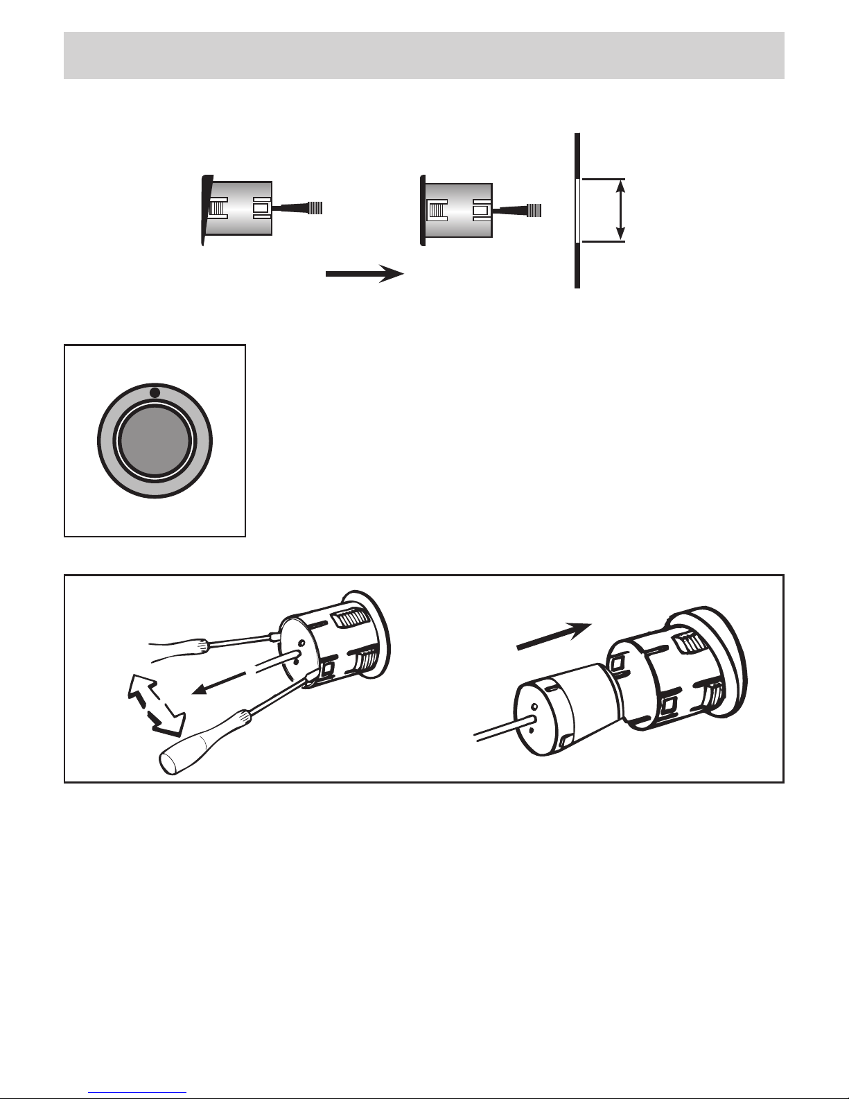
I - I sensori vengono forniti con anello piano già inserito. Nel caso necessiti per l’installazione su paraurti, l’anello
inclinato, sostituire quello presente facendo leva sulle linguette di aggancio.
GB - The sensors comes fitted on the flat adapter. Should the inclined adapter be required, for installation on
the bumper, take the flat adapter off by lifting the small attachment hooks.
FR - Les capteurs arrivent déjà équipés avec l’adaptateur plat. En cas de nécessité de l’adaptateur incliné, pour
installation sur le pare-chocs, éliminer l’adaptateur plat en soulevant les languettes d’encastrement.
D - Die Sensoren sind ursprünglich am flachen Adapter angekoppelt. Sollte, für die Stoßstangen-Montage, der
geneigte Adapter notwendig sein, genügt es, die kleinen Einrast-Blöcke anzuheben und den flachen Adapter zu
entfernen.
E - Los sensores se suministran con los anillos planos ya insertados. En el caso de que la instalación requiera
los anillos inclinados, se pueden sustituir haciendo leva en los ganchos como se muestra en la figura.
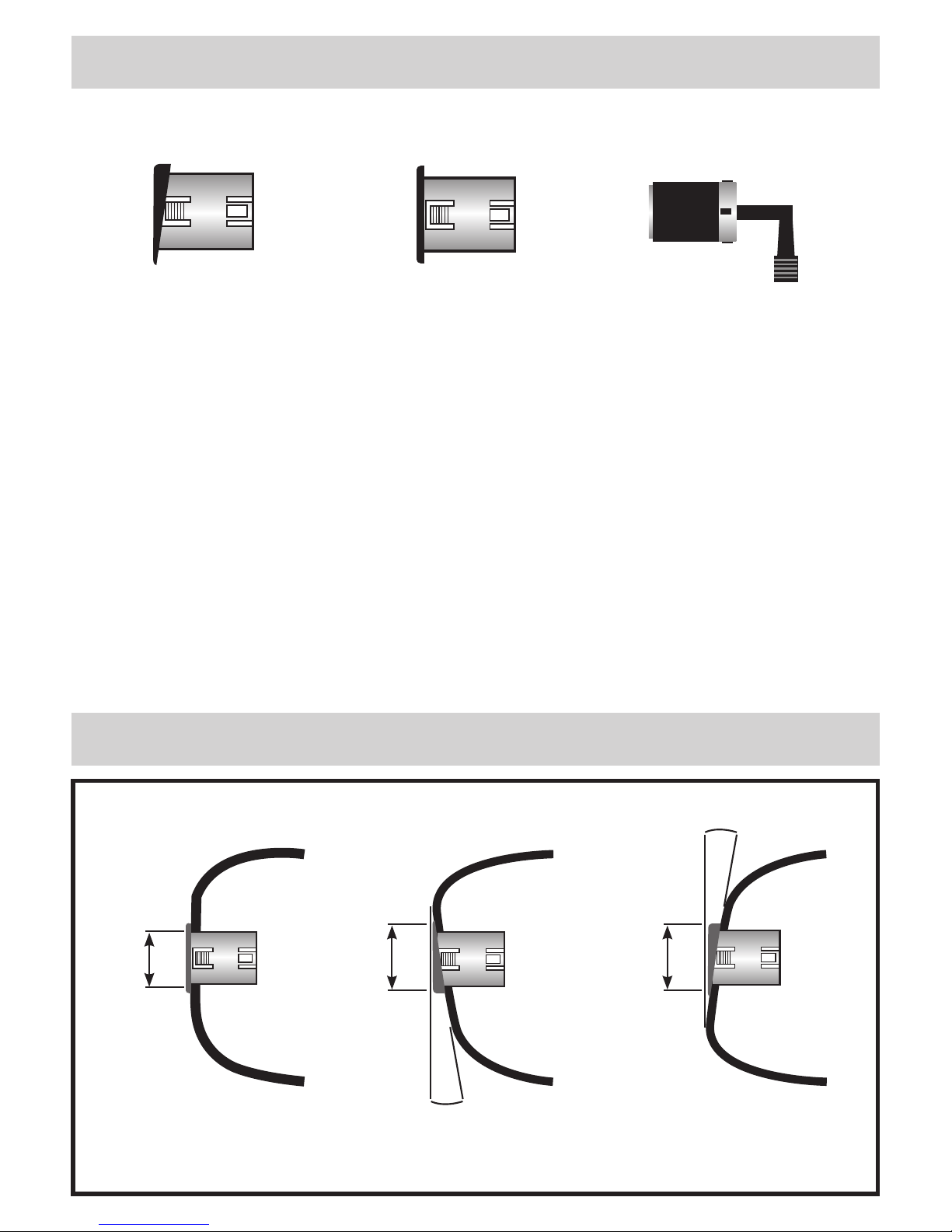
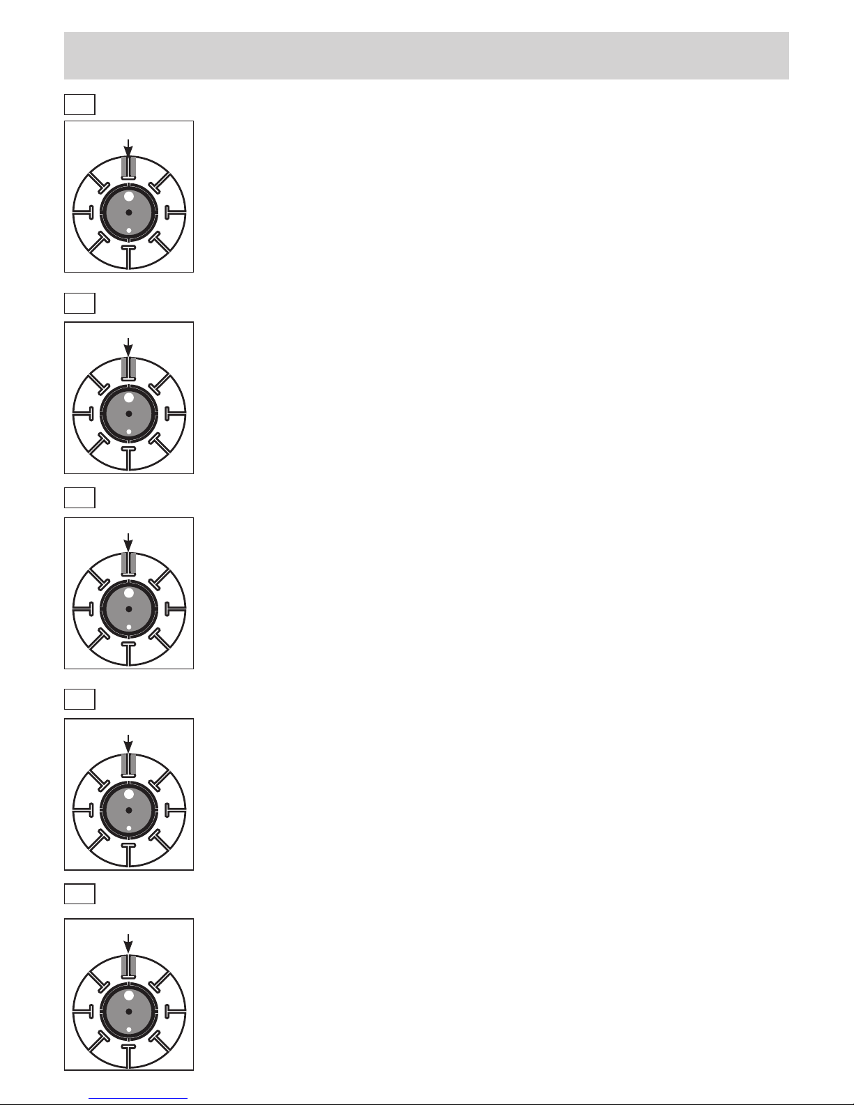
I - Per una corretta installazione i sensori devono essere posizionati con il punto
di riferimento rivolto verso l’alto o verso il basso.
GB - For a correct installation, the sensors have to be positioned with the bench-
mark showing up or down.
FR - Pour une installation correcte, les capteurs doivent être positionnés avec le
point de repère retourné vers le haut ou vers le bas.
D - Um die Installation korrekt durchzuführen, muss der Orientierungs-Punkt nach
oben oder nach unten gerichtet sein.
E - Para una correcta instalación los sensores tienen que estar posicionados con
el punto de referencia hacia arriba o bien hacia abajo.
06904 - 06908

8
9
I -
CON SUPPORTO PIANO
Praticare i fori. Il sensore può sporgere dal supporto fino a 4 mm per compensare lo spessore del paraurti, nel caso necessiti di
una sporgenza superiore, asportare il fermo di fine corsa.
Applicare il supporto al paraurti, rispettando il riferimento di colore bianco.
Sfilare l'involucro sensore, applicare colla per ABS (tipo Bostick) e infilarlo facendolo sporgere il necessario.
ATTENZIONE: Pulire con acetone la zona dove verrà applicato il supporto e riscaldarla nel caso di bassa temperatura.
GB -
WITH FLAT SUPPORT
Drill installation holes. The Sensor may overhang the support by max. 4mm, in due account of the bumper-thickness. Should the
4mm overhang-limit not be sufficient, eliminate the far-end blockade.
Install the support onto the bumper by taking the white bench-mark as reference.
Slide-out the sensor-housing, apply glue for ABS (example Bostick). Push sensor-housing in place, with required overhanging
millimeters.
ATTENTION: Clean surface, where support will be installed, with acetone. Under cold weather-conditions, warm surface up.
FR-
AVEC SUPPORT PLAT
Faire des trous. Le capteur peut ressortir du support jusqu'à 4 mm pour compenser l'épaisseur du pare-chocs, si vous nécessi-
tez d'une saillie supérieure, enlever le bloque de profondeur.
Appliquer le support au pare-chocs, en respectant l’indication de couleur blanche.
Enlever la capsule du capteur, mettre la colle pour ABS (type Bostick) et l’enfiler en faisant ressortir le nécessaire.
ATTENTION : nettoyer avec de l'acétone la partie où le capteur sera appliqué et la réchauffer en cas de basse température.
D -
MIT FLACH-ADAPTER
Befestigungsbohrungen vornehmen. Der Sensor darf, wegen der Stoßstange, max. 4mm herausragen. Sollten die 4mm nicht
genügen, die End-Blockierung einfach entfernen.
Adapter an der Stoßstange befestigen und sich dabei an der weißen Farbe orientieren.
Sensor-Halterung herausziehen; Kleber für ABS (z.B. Bostick) auftragen ; Sensor-Halterung wieder einsetzen und nach Bedarf
hervorragen lassen.
WICHTIG: Installations-Oberfläche mit Lösungsmittel reinigen. Bei Kälte, Oberfläche anwärmen.
E -
CON SOPORTE PLANO
Hacer los orificios. El sensor puede sobresalir del soporte hasta 4 mm. para compensar el grosor del parachoques, en el caso
de que deba sobresalir más, quitar el bloqueo de fin de carrera.
Aplicar el soporte al parachoques, respetando el punto de referencia de color blanco.
Quitar el involucro sensor, aplicar pegamento para ABS (cola de contacto tipo Bostick) e introducirlo haciéndolo sobresalir lo
necesario.
ATENCION: Limpiar con acetona la zona donde será aplicado el soporte y calentarla en el caso de bajas temperaturas.
FORO
HOLE
Ø 18 mm
BIANCO / WHITE / BLANCHE
WEISS / BLANCO FINE CORSA / FAR-END BLOCKADE
BLOQUE DE PROFONDEUR
END-BLOCKIERUNG
BLOQUEO DE FIN DE CARRERA
BIANCO / WHITE / BLANCHE
WEISS / BLANCO
4 mm
INSTALLAZIONE INSTALLATION INSTALLATION EINBAU INSTALACIÓN
06906 - 06909

10
11
INSTALLAZIONE INSTALLATION INSTALLATION EINBAU INSTALACIÓN
FORO
HOLE
Ø 22 mm
BIANCO / WHITE / BLANCHE
WEISS / BLANCO
BIANCO / WHITE / BLANCHE
WEISS / BLANCO
I -
SUPPORTO INCLINATO
Praticare i fori. Applicare il biadesivo solo sul supporto. Inserire il supporto nel foro e asportare l'eventuale parte sporgente
tramite carta abrasiva, oppure applicando un altro biadesivo. Asportare la pellicola di protezione del biadesivo e collocare defini-
tivamente il supporto al paraurti rispettando il riferimento di colore bianco. Applicare colla per ABS (tipo Bostick) all'involucro del
sensore ed inserirlo nel supporto senza farlo sporgere.
ATTENZIONE: Pulire con acetone la zona dove verrà applicato il supporto e riscaldarla nel caso di bassa temperatura.
GB -
INCLINED SUPPORT
Drill installation holes. Apply bi-adhesive tape only to the support. Introduce the support into the hole and rub-away the possible
overhanging part, or apply a second bi-adhesive tape.
Lift protection-slip from the bi-adhesive tape and stick the support definitely onto the bumper, by watching the white bench-mark.
Apply glue for ABS (example Bostick) onto the sensor-housing. Place sensor-housing Into the support, perfectly on the edge.
ATTENTION: Clean surface, where support will be installed, with acetone. Under cold weather-conditions, warm surface up.
FR-
SUPPORT INCLINE
Faire des trous. Mettre le bi adhésif seulement sur le support. Insérer le support dans le trou et emporter éventuellement la partie
ressortie moyennant du papier abrasif, ou en y appliquant un autre bi adhésif.
Enlever le film de protection du bi adhésif et positionner définitivement le support au pare-chocs en respectant l'indication de cou-
leur blanche. Mettre la colle pour ABS (type Bostick) sur la capsule du capteur et l'insérer dans le support sans le faire ressortir.
ATTENTION : nettoyer avec de l'acétone la partie où le capteur sera appliqué et la réchauffer en cas de basse température
D -
GENEIGTER ADAPTER
Installationsbohrungen vornehmen. Beidseitig klebenden Streifen nur am Adapter anbringen. Adapter in die Bohrung geben. Den
eventuell hervorstehenden Teil des Adapters wegschmirgeln oder einen zweiten Klebestreifen auftragen.
Schutzfolie vom Klebestreifen entfernen und Adapter definitiv auf der Stoßstange positionieren. Dabei den weiß markierten An-
haltspunkt beachten. Sensor-Halter mit Kleber bestreichen (z.B. Bostick für ABS) und Kanten-genau in den Adapter setzen.
WICHTIG: Die für den Adapter vorgesehene Installations-Oberfläche mit einem Lösungsmittel säubern und, bei kalten Wetterver-
hältnissen, anwärmen.
E -
SOPORTE INCLINATO
Hacer los orificios. Aplicar el biadhesivo solo sobre el soporte. Introducir el soporte en el orificio y quitar eventualmente la
parte que sobresale mediante papel de lija o bien aplicando otro biadhesivo.
Quitar la película de protección del biadhesivo y fijar definitivamente el soporte al parachoques respetando el punto de refe-
rencia de color blanco. Aplicar pegamento para ABS (cola de contacto tipo Bostick) al involucro del sensor e introducirlo en
el soporte evitando que sobresalga.
ATENCION: Limpiar con acetona la zona donde será aplicado el soporte y calentarla en el caso de bajas temperaturas.
4 mm
FINE CORSA / FAR-END BLOCKADE
BLOQUE DE PROFONDEUR
END-BLOCKIERUNG
BLOQUEO DE FIN DE CARRERA
06908 - 06909

10
11
I- Sfilare il sensore dall'involucro.
Proteggere la parte in gomma con nastro adesivo.
Procedere alla verniciatura.
Inserire il sensore nell'involucro rispettando le guide.
GB - Extract Sensor from Housing-pa rt
Protect rubber-parts by means of the adhesive tape.
Carry out painting-procedure.
Push Sensor into the Housing, respecting
the sliding part.
FR - Enlever le capteur de la capsule en plastique.
Protéger la partie en caoutchouc avec du ruban adhésif
Peindre.
Insérer le capteur dans la capsule en plastique
en respectant les instructions.
D - Sensor aus der Halterung ziehen
Gummi-Teile mittels Klebestreifen schützen
Lackierung vornehmen
Sensor, unter Berücksichtigung der Gleitleisten,
wieder in die Halterung schieben.
E - Quitar el sensor del involucro.
Proteger la parte en goma con cinta adhesiva.
Proceder al pintado.
Introducir el sensor en el involucro respetando las guías.
VERNICIATURA • PAINTING • VERNISSAGE • ANSTRICH • BARNIZADO
06904 - 0690606908 - 06909
12
13
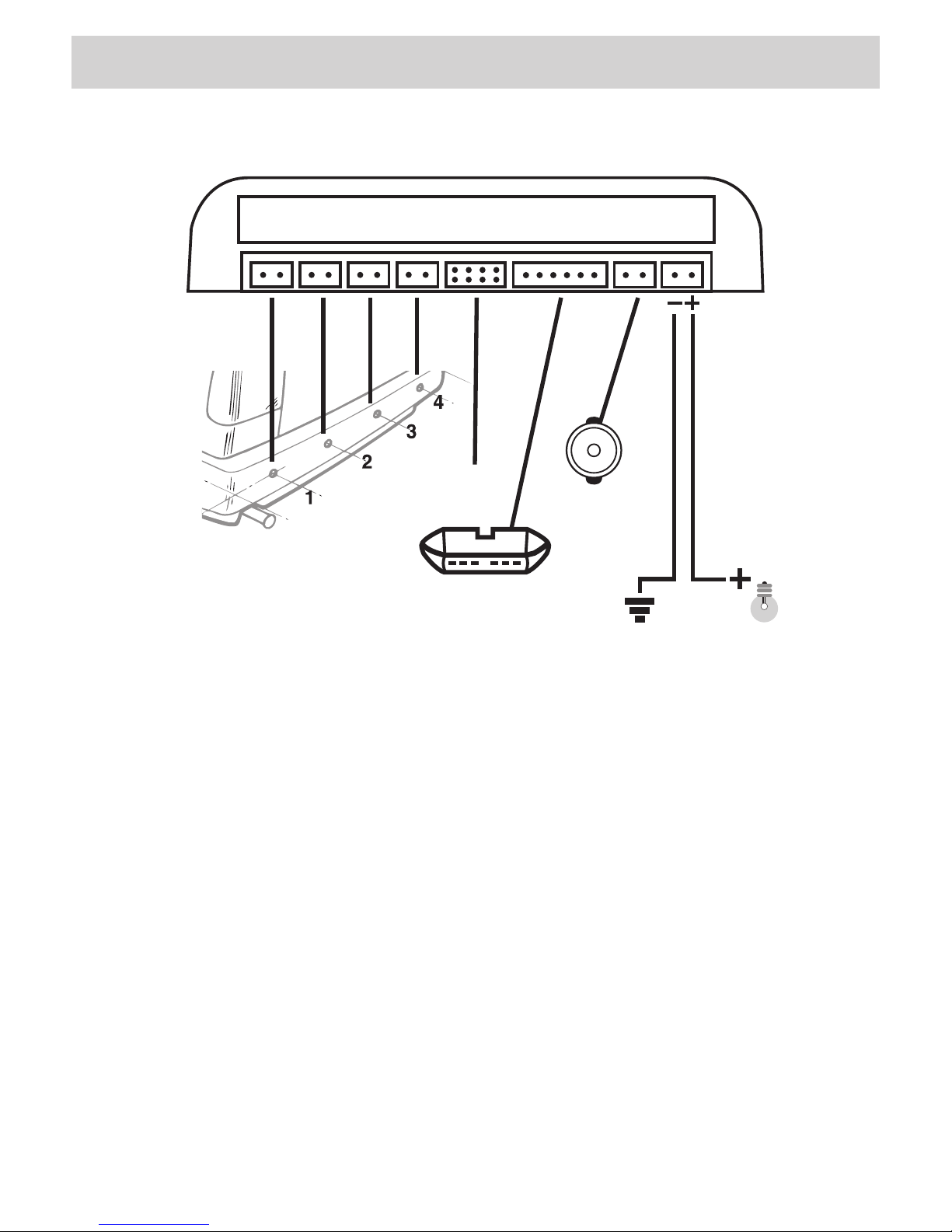
COLLEGAMENTI CONNECTIONS CONNEXIONS ANSCHLÜSSE CONEXIONES
1 2 3 4
DSPPRG BZ/DC
LUCI RETROMARCIA
REVERSE LIGHTS
DISPLAY
OPTIONAL 06911-912
AUTOBLANKING
BUZZER
06904 - 06908
I- Il sistema si aziona inserendo la retromarcia.
Un beep acustico segnala l’avvenuta attivazione.
I sensori determinano un’area di copertura al vei-
colo con un angolo di 160° in orizzontale e di 60°
in verticale.
Per un corretto funzionamento, manovrare il
veicolo a bassa velocità (max. 5 Km/h).
GB - The systems enters into effect as soon as
the backward-gear is inserted. The activation is
signalled by an acoustic beep-sound. The sensors
cover an area resulting from a horizontal angle of
160° and a vertical angle of 60°.
To make sure that the system can work cor-
rectly, please move the car slowly (max. 5
Km/h).
FR - Le système se branche automatiquement
lorsqu’on met la marche arrière. Un bip acoustique
signale l’activation.
Les senseurs couvrent une aire angulaire horizon-
tale de 160° et une verticale de 60°.
Pour un correct fonctionnement du système, il
faut conduire la voiture à une vitesse très ré-
duite (max. 5 Km/h).
D - Das System wird durch Einlegen des Rück-
wärtsganges aktiv. Die Aktivierung wird durch
einen akustischen Piep-Ton bestätigt.
Die Sensoren decken einen horizontalen Winkel
von 160° und einen vertikalen von 60° ab
Um die gute Funktion des Systems zu garan-
tieren, muss der Wagen langsam manövriert
werden. (max. 5 Km/h).
E - El sistema se activa insertando la marcha atrás.
Un beep señala que ha sido activado
Los sensores determinan un área de cobertura al
vehículo con un ángulo de 160º en horizontal y de
60° en vertical.
Para un correcto funcionamiento maniobrar el
vehículo a baja velocidad (max. 5 Km/h).

12
13
COLLEGAMENTI CONNECTIONS CONNEXIONS ANSCHLÜSSE CONEXIONES
5
7
8
6
5 7 8 6
DSPPRG B/G/A
OPTIONAL 06911-912
I-
Il sistema rimarrà attivo per 30 sec. dopo aver disinserito la retromarcia.
GB -
When changing from reverse-gear to another gear, the system remains active for
30 seconds.
FR -
Das System bleibt, nachdem der Rückwärtsgang entfernt worden ist, weitere
30 Sekunden aktiv.
D -
Après la désinsertion de la marche arrière, le système reste actif pour 30 sec.
E -
El sistema quedará activo durante 30 s después de desembragar la marcha atrás.
I-
Collegato tramite interruttore al filo rosso il sistema si attiva manualmente.
Collegato anche alla luce freni si attiva tutte le volte che si frena
e si disattiva dopo pochi secondi.
GB -
Manual activation of the system is obtained by connecting it, through a switch,
to the red cable. By connecting the system to the brake-lights, it activates
and de-activates after a few seconds, every time the brake gets activated.
FR -
Branché à travers l’interrupteur au fil rouge, le système s’active manuellement.
Branché à la lumière des freins, il s’active à chaque freinage et se désactive
après quelques secondes.
D -
Um die manuelle Aktivierung zu bewirken, mittels Schalter, an das rot
Kabel anschließen. Das System aktiviert sich und de-aktiviert sich nach
wenigen Sekunden, wenn es gleichzeitig auch am Bremslicht angeschlossen ist.
E -
Conectado mediante interruptor al cable rojo el sistema se activa
manualmente. Conectado también a la luz del freno se activa todas las veces
que se frena y se desactiva después de pocos segundos.
BUZZER
OR DISPLAY
ROSSO - RED - ROUGE - ROT - ROJO
NERO - BLACK - NOIR - SCHWARZ - NEGRO
LUCI
RETROMARCIA
REVERSE-GEAR
LIGHTS
VERDE - GREEN - VERT - GRÜN - VERDE
GIALLO - YELLOW - JAUNE - GELB - AMARILLO
LUCE / LIGHT
STOP
12 V
2
1
1
2
06906 - 06909
0
I
Cavo / Cable VERDE - GREEN - VERT - GRÜN
Cavo / Cable GIALLO - YELLOW - JAUNE - GELB - AMARILLO
14
15
AUTOBLANKING
GIALLO - YELLOW - JAUNE - GELB - AMARILLO
MARRONE - BROWN - MARRON - BRAUN - MARRÓN
BLU - BLUE - BLEU - BLAU - AZUL
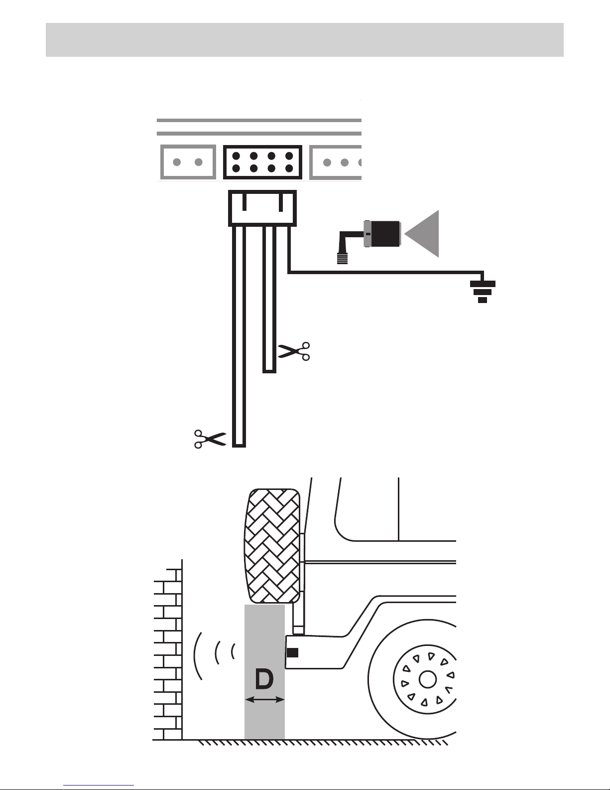
D = 70 cm.
D = 50 cm.
-5°
1 2 3 4
DSP
PRG
BZ/DC

14
15
AUTOBLANKING
I-
ESTENSIONE DEL LIMITE DI RILEVAMENTO IN CASO DI RUOTA DI SCORTA SPORGENTE (TIPO SUV) O DI
GANCIO TRAINO POSTERIORE.
• Misurare la sporgenza della ruota di scorta o gancio traino rispetto ai sensori installati sul paraurti.
• Tagliare il filo Blu per evitare il rilevamento dei sensori fino a 50 cm.
• Tagliare il filo Marrone per evitare il rilevamento dei sensori fino a 70 cm.
• Rimuovendo il connettore PRG il rilevamento dei sensori torna a 20 cm.
• Collegando il filo giallo a massa si diminuisce l’angolo di trasmissione dei sensori di 5 gradi.
GB -
EXTENDING THE DETECTION-LIMIT IN THE PRESENCE OF OVERHANGING SPARE-TYRE (SUV-types) OR
REAR DRAGGING-HOOK.
• Measure the part of the spare-tyre or of the dragging-hook overhanging the sensors situated on the bumper.
• Cut the Blue cable, in order to stop the sensors from detecting within 50cm.
• Cut the Brown cable, In order to stop the sensors from detecting within 70cm.
• By removing the PRG-connector, the detection-distance of the sensors will be re-established at 20cm.
• By connecting the Yellow cable to the Mass, the transmission-angle of the sensors will be reduced by 5 degrees.
FR - EXTENSION DE LA LIMITE DE DETECTION EN CAS DE ROUE DE SECOURS EXTERNE (EXEMPLE SUV)
OU DE CROCHET POUR REMORQUE POSTÉRIEURE.
• Mesurer la saillie de la roue de secours ou le crochet pour remorque par rapport aux capteurs installés sur le
pare-chocs.
• Couper le fil bleu pour éviter la détection des capteurs jusqu’à 50 cm.
• Couper le fil marron pour éviter la détection des capteurs jusqu’à 70 cm.
• En enlevant le connecteur PRG la détection des capteurs retourne à 20 cm.
• En branchant le fil jaune à masse, l’angle de transmission des capteurs se réduit de 5 degrés.
D -
ERFASSUNGS-LIMIT AUSWEITEN, BEI HERVORSTEHENDEM ERSATZ-REIFEN (SUV-Fahrzeuge) ODER
ABSCHLEPP-HAKEN.
• Abmessen, wie weit Ersatz-Reifen bzw. Abschlepp-Haken hervorstehen, im Vergleich zu den Parksensoren auf der
Stoßstange.
• Blaues Kabel abschneiden, um die Erfassung bis 50cm auszuschließen.
• Braunes Kabel abschneiden, um die Erfassung bis 70cm auszuschließen.
• PRG-Stecker entfernen, so dass die Sensoren wieder bei 20cm Abstand wirken.
• Verbindet man das gelbe Kabel mit der Masse, reduziert sich der Sende-Winkel der Sensoren um 5 Grad.
E - EXTENSION DEL LIMITE DE DETECCION EN CASO DE RUEDA DE REPUESTO EN EL PORTON
TRASERO (TIPO SUV) O BIEN DE ENGANCHE DE REMOLQUE TRASERO.
• Medir la distancia entre los sensores montados en el parachoques y el final de la rueda de repuesto o el
enganche de remolque.
• Cortar el cable de color AZUL para evitar la detección de los sensores hasta 50 cm.
• Cortar el cable Marrón para evitar la detección de los sensores hasta 70 cm.
• Quitando el conector PRG la detección de los sensores vuelve a 20 cm.
• Conectando el cable amarillo a la masa del coche se disminuye el ángulo de trasmisión de los sensores
de 5º grados.
16
17
I
IMPORTANTE: Non installare per nessun motivo i sensori ad un'altezza inferiore a 45 cm. Il mancato
rispetto di questa misura comporterà false segnalazioni compromettendo il corretto funzio-
namento del dispositivo.
• Applicare il supporto al paraurti rispettando il riferimento di colore bianco il quale deve
essere posizionato verso l'alto o verso il basso.
ATTENZIONE: un errato posizionamento od orientamento dei sensori può compromettere
l’intera funzionalità del sistema.
• Fissare i cavi dei sensori lungo la parete interna del paraurti.
NON ALTERARE LA LUNGHEZZA DEI CAVI.
GB
IMPORTANT: Never install the sensors at less than 45cm from the ground. At a smaller height, the sensors
would reveal false information and badly influence the working-process of the whole sys-
tem.
• Install the support to the bumper, referring to the white bench-mark which has to be up or
down.
ATTENTION: an incorrect positioning and/or orientation of the sensors can compromise the
correct functioning of the whole system.
• Fix the sensor cables along the internal wall of the bumper.
DO NOT ALTER CABLE-LENGTH
FR
IMPORTANT: Pour aucunes raisons, les capteurs doivent être installés à une hauteur inférieure à 45 cm.
Le non-respect de cette mesure impliquera de faux signaux tout en compromettant le cor-
rect fonctionnement du dispositif.
• Appliquer le support au pare-chocs en respectant l’indication de couleur blanche, qui doit
être positionné vers le haut ou vers le bas.
ATTENTION: un mauvais positionnement ou orientation des capteurs peut compromettre
tout le fonctionnement du système.
• Fixer les câbles des capteurs le long de la paroi interne du pare-chocs.
NE PAS MODIFIER LA LONGUEUR DES CÂBLES.
D
WICHTIG: die Sensoren, auf keinen Fall, tiefer als 45cm vom Boden installieren. Bei einer geringeren Instal-
lationshöhe besteht die Gefahr von Fehl-Informationen, mit konsequenter Beeinträchtigung
des gesamten Systems.
• Adapter an der Stoßstange so befestigen, dass der weiß markierte Anhaltspunkt sich
entweder oben oder unten befindet.
WICHTIG: eine falsch vorgenommene Positionierung bzw. Orientierung der Sensoren kann
die Funktion des gesamten Systems beeinträchtigen.
•
Die Kabel der Sensoren, innen entlang der Stosstange.
DIE KABELLÄNGE MUSS, AUF JEDEN FALL, UNVERÄNDERT BLEIBEN.
E
IMPORTANTE: No instalar por ningún motivo los sensores a una altura inferior a 45 cm. desde el suelo.
No respectar esta medida compromete el correcto funcionamiento del dispositivo, con
falsas señalaciones.
• Aplicar el soporte al parachoques respetando el punto de referencia de color blanco, que
debe ser posicionado hacia arriba o hacia abajo.
ATENCION: un equivocado posicionamiento de los sensores puede comprometer la entera
funcionalidad del sistema.
• Fijar los cables de los sensores a lo largo de la pared interna del parachoques.
NO ALTERAR LA LONGITUD DE LOS CABLES.
WHITE
BLANCHE
WEISS
BLANCO
INSTALLAZIONE INSTALLATION INSTALLATION EINBAU INSTALACIÓN
BIANCO

16
17
AVVERTENZE IMPORTANT NOTICE IMPORTANTE WICHTIGE HINWEISE ADVERTENCIAS
I-
False segnalazioni possono essere causate da:
- errato posizionamento dei sensori,
- operazioni di retromarcia in discese ad elevata pen-
denza,
- operazioni di manovra a forte velocità,
- presenza di forte vento,
- abbassamento della parte posteriore del veicolo a pieno
carico (inclinazione superiore a 8°),
- interferenze dovute a parti sporgenti nel retro del
veicolo, es: ruote di scorta nei fuoristrada, portapacchi,
portabiciclette posteriori, gancio di traino, etc.
- interferenza da altre frequenze ultrasoniche,
- neve, ghiaccio o eccessiva sporcizia depositati sui
sensori.
La centrale riconosce, all'inserimento della retromarcia, le
anomalie con i seguenti avvisi:
1 beep - sensore 1 danneggiato (sostituire)
2 beep - sensore 2 danneggiato (sostituire)
3 beep - sensore 3 danneggiato (sostituire)
4 beep - sensore 4 danneggiato (sostituire)
beep continui - tutti i sensori danneggiati.
GB -
False signalisations can be provoked through:
- incorrect sensor-positioning,
- backward-gear operations on very strong slopes,
- manoeuvering operations at high speed,
- presence of strong wind,
- rear part of the car at full charge, with a low-down
(inclination of more than 8°).
- Interferences due to overhanging rear parts like: jeep
spare-tyre, parcel-rack, bicycle-holder, towing-hook
etc.
- Interferences from other ultrasonic frequencies.
- Snow, ice or excessive dirt on the sensors.
From the moment the reverse-gear is inserted, the
Central-Box will search for possible existing problems
and will signal them as follows:
1 beep-signal - sensor 1 damaged (to be replaced)
2 beep-signals - sensor 2 damaged (to be replaced)
3 beep-signals - sensor 3 damaged (to be replaced)
4 beep-signals - sensor 4 damaged (to be replaced)
Continuous beeping-signal - all sensores damaged.
FR -
Des fausses signalisations peuvent être
causées par les circonstances suivantes:
- positionnement erroné des senseurs,
- opérations de recul sur un terrain de forte pente,
- opérations de manoeuvre à grande vitesse,
- présence de vents violents,
- baisse de la partie postérieure du véhicule à plein charge
(donnant lieu à une inclinaison supérieure à 8°),
- interférences dues à des parties proéminentes sur
l’arrière de la voiture, exemple: roue de secours sur les
jeeps, porte-bagages, porte-vélos, crochet d’attelage
etc.,
- Interférences par des autres fréquences ultrasoniques,
- neige, verglas ou saleté sur les senseurs.
Dès que l'on introduit la marche arrière, l'unité centrale
reconnait les anomalies et les indiquent comme suit:
1 bip - senseur 1 abimé (à remplacer)
2 bips - senseur 2 abimé (à remplacer)
3 bips - senseur 3 abimé (à remplacer)
4 bips - senseur 4 abimé (à remplacer)
bip continu - tous les senseurs abimés.
D -
Eine fehlerhafte Signalisierung kann unter
folgenden Umständen zustande kommen:
- bei falsch positionierten Sensoren,
- beim Rückwärtsparken an steilem Abhang,
- Fahrmanöver bei hoher Geschwindigkeit,
- bei starkem Wind,
- bei voll beladenem Auto und einer Senkung des
Wagen-Hecks von mehr als 8°,
- bei hinten am Auto herausragenden Teilen (z.B. Ersat-
zreifen bei Geländewagen, Gepäckhalter, rückwärtige
Fahrradständer, Abschlepphaken etc.),
- bei Einfluss anderer Ultraschall-Frequenzen,
- Schnee, Eis oder Schmutzschichten auf den Sensoren.
Sobald der Rückwärtsgang eingelegt ist, beginnt die Zen-
traleinheit die Suche nach möglichen Unstimmigkeiten
und zeigt diese wie folgt an:
1 Piep-Ton = Sensor 1 beschädigt (austauschen).
2 Piep-Töne = Sensor 2 beschädigt (austauschen).
3 Piep-Töne = Sensor 3 beschädigt (austauschen).
Anhaltender Piep-Ton = alle Sensoren beschädigt.
E -
Falsas señalizaciones pueden ser causadas por:
- equivocado posicionamiento de los sensores,
- operación de marcha atrás en calles o carreteras de
elevada pendencia,
- maniobras de aparcamiento demasiado rápida,
- presencia de viento fuerte,
- fuerte bajada posterior del vehículo debido a plena
carga (inclinación superior a 8°),
- Interferencias de otras frecuencias ultrasónicas,
- nieve, hielo, o excesiva suciedad depositada encima
de los sensores.
En el caso de que las conexiones sean equivocadas,
o parte del sistema este desconectado, o averiado, la
unidad central, avisa al conductor con una secuencia de
beep prolongados, con un intervalo de 2 beep breves. En
el caso de tener instalado el display el aviso será tambien
visivo en cuanto empezaran a parpadear los leds del
mismo.
La centralita reconoce, cuando se inserta la marcha atrás,
eventuales anomalías serán señaladas de la siguiente
forma:
1 Beep - sensor 1 dañado (sustituir)
2 Beep - sensor 2 dañado (sustituir)
3 Beep - sensor 3 dañado (sustituir)
4 Beep - sensor 4 dañado (sustituir)
Beep continuos - todos los sensores están dañados.

18
19
Alimentazione / Power supply DC 10 - 25V
Massima potenza assorbita / Max power consumption 0.5W
Massimo assorbimento / Max current consumption 20mA / 200mA with Display (optional)
Temperatura di esercizio / Operating Temperature - 20°C / +70°C
Frequenza di trasmissione / Transmitting frequency 40KHz (Ultrasonic)
Metodo di ricezione / Sensing Method Asymmetrical
Pressione sonora avvisatore acustico / Buzzer sound pressure level 70-90 dB at 10 cm
Tempo di risposta del sistema / System response time 0.12 sec
Dimensioni unità centrale / Control box unit dimensions mm L. 98 P. 72 H. 25
Numero sensori / Sensor units 4 pcs.
06908 - 06904
Lunghezza cavo sensori / Sensor cable lenght 2,5 m
Lunghezza cavo alimentazione / Power cable length 1,2 m
Lunghezza cavo avvisatore acustico / Buzzer cable length 2,5 m
06909 - 06906
Lunghezza cavo sensori / Sensor cable lenght 5 m
Lunghezza cavo alimentazione / Power cable length 1 m
Lunghezza cavo avvisatore acustico / Buzzer cable length 3 m
CARATTERISTICHE
TECNICHE SPECIFICATIONS CARACTERISTIQUES
TECHNIQUES TECHNISCHE
DATEN CARACTERÍSTICAS
TÉCNICAS

18
19
I - La valutazione dell’ostacolo è di esclusiva responsabilità del conducente che deve adottare una guida
prudente e utilizzare comunque gli specchi retrovisori. Il costruttore, i distributori ed i rivenditori non
sono responsabili di eventuali incidenti inaspettati.
GB - The driver is totally responsible for the obstacle evaluations and has to drive carefully, making use also of
the rear-mirrors. The Manufacturer, Distributors and Sales Points cannot be made responsible
for unexpected accidents.
FR - L’évaluation de l’obstacle est de responsabilité du conducteur qui est tenu à conduire la voiture avec
prudence en utilisant les rétroviseurs. Le Constructeur, les Distributeurs et les Revendeurs ne sont donc
pas responsables des éventuels accidents inattendus.
D - Der Fahrer muss das im Wege stehende Hindernis selbst einschätzen, beim Parken langsam vorgehen und
sich durch die Rückspiegel vergewissern. Hersteller, Vertriebe und Händler sind für etwaige
unvorhergesehene Unfälle daher nicht haftbar zu machen.
E - La evaluación del obstáculo es de exclusiva responsabilidad del conductor, que tiene que adoptar todas
las precauciones, y usar de todas formas los espejos retrovisores, en cuanto el uso de este dispositivo
no lo exonera de su obligación de mirar en la dirección hacia la cual se desplaza el vehículo.
El fabricante, los distribuidores y los instaladores, etc. no son responsables de eventuales percances, o
accidentes inesperados.
IMPORTANTE IMPORTANT IMPORTANTE WICHTIGER
HINWEIS IMPORTANTE

Distribuito da: Phonocar S.p.A.
Via F.lli Cervi, 167/C - 42100 Reggio Emilia - Tel. +39 0522 941621 - Fax +39 0522 160 2093
www.phonocar.com • e-mail: [email protected]
Il prodotto non deve essere smaltito con i rifiuti domestici. Per ulteriori informazioni consultare il sito www.phonocar.it
This Product must NOT be treated as a domestic waste. For further information, please read homepage www.phonocar.it
DICHIARAZIONE DI CONFORMITÀ aIle direttive 72/245/EEC > 2005/83/EC
DECLARATION OF CONFORMITY to the directives 72/245/EEC > 2005/83/EC
IT Phonocar dichiara che il 06904-06906-06908-06909 è conforme ai requisiti essenziali
e a tutte le altre disposizioni pertinenti stabilite dalla direttiva 72/245/EEC > 2005/83/EC.
GB Phonocar declares that this unit 06904-06906-06908-06909 is in compliance with the essential requirements and other revelant provisions
of Directive 72/245/EEC > 2005/83/EC.
FR Phonocar dèclare que l’appareil 06904-06906-06908-06909 est conforme aux exigences essentielles et aux autres dispositions pertinentes
de la directive 72/245/EEC > 2005/83/EC.
DPhonocar erklärt, dass dieser 06904-06906-06908-06909 in Übereinstimmung ist mit den grundlegenden Anforderungen und den anderen
relevanten Vorschriften der Richtlinie 72/245/EEC > 2005/83/EC.
E Phonocar declara que el 06904-06906-06908-06909 cumple con los requisitos esenciales y cualesquiera otras disposiciones aplicables
o exigibles de la Directiva 72/245/EEC > 2005/83/EC.
This manual suits for next models
3
Table of contents
Other SEC Automobile Accessories manuals


