Secheron UR46-81S User manual
Document number: SG104148TEN
Language: En Revision: B01 Issue date: 20.8.2012
Instructions manual
DC High speed circuit-breaker
UR46-81/82S
Number of pages: 68
SG104148TEN-B01 Established by: Desbaillet Checked by: Released by:
Signature:
Date:
Secheron
r*
r« i
i»
m
I'Lfc
•f J
» ;
I 1
fl Kv-Cr
Checked by: i ft <i l(A Released by:SG104148TEN-B01 Established by: Desbaillet
W'oLlL ;
Signature: i—
lo.oi v>n
'Ztf. P lO'fZ-
Date:

Document number: SG104148TEN Revision: B01 Issue date: 20.8.2012
Copyright© 2012 Sécheron SA - This document is not contractual and contains information corresponding to the level of technology at the date of release.
2File: 1-UR46-8S_front.fm
Copyright© 2012 Sécheron SA
Geneva, Switzerland
Reproduction in whole or part, or disclosure to a third party prohibited.
Design modifications
This document is not contractual and contains information corresponding to the level of tech-
nology at the date of release. Sécheron reserves the right to modify and/or improve the product,
whose characteristics are described in these documents, as required by new technology at any
time. It is the purchaser’s responsibility to inform himself, no matter what the circumstances, of
the product’s maintenance conditions and requirements.
Sécheron reserves all rights, especially those arising from our general delivery conditions.
Document information
In case of dispute between a non-English version of this publication and its corresponding
English version, the English one is the only legal version.
It is important to keep this manual for the lifetime of the equipment and to pass it on to any
subsequent owner or user.
Structure of this instruction manual
• Chapters A to F: all the information needed to understand, install, use, perform the mainte-
nance and order a spare part for the standard version of this device.
• Chapter G. Options: all the information needed to understand, install, use, perform the main-
tenance and order an option or a spare part for these options.
• Chapter H. Customization: all the information needed to install, use, perform the maintenance
and order a part for these customized assemblies (chapter not included without customiza-
tion).
Note! When the “Customization” chapter is present, always refer to it at first before referring to the
other chapters which are intended to the standard device.
Throughout this manual:
• the numbers between brackets (x) refer to the corresponding positions in the figure shown in
the same sub-chapter.
the blue texts are hyperlinks, to be clicked on to navigate in electronic files; they are black in
printed manuals.
Sécheron SA Tel. +41 (0) 22 739 41 11
Rue du Pré-Bouvier 25 Fax:+41 (0) 22 739 48 11
1217 Meyrin- Geneva info@secheron.com
Switzerland www.secheron.com
Secheron

UR46-81/82S Revision changes
Document number: SG104148TEN Revision: B01 Issue date: 20.8.2012
Copyright© 2012 Sécheron SA - This document is not contractual and contains information corresponding to the level of technology at the date of release.
File: 2-UR46-8S_rev_en.fm 3
Revision changes
Version: SG104148TEN
Revision Date Established by: Description
A00 18.4.08 Desbaillet New manual
B00 19.12.08 Desbaillet
B.1.2: added (Tamb=40 °C); modified INss text.
Exchanged B.2 and B.3.
C.3: modified.
C.8.2: added text.
C.9.2: modified.
D.1: changed greases.
D.7.6: changed text.
D.8.2 + D.9 + D.11: removed Molycote.
G.1.2: added “and the lever (9) “; changed drawing.
G.1.3: added.
G.3: added kit number.
G.3.1 + G.3.2: added stroke.
G.3.1 + G.4.1 + G.6: added important.
And many small updates throughout the manual.
B01 20.8.12 Desbaillet
A.2: added safety rules.
B.3: modified.
C.1: modified all.
C.8: added.
C.12.1: added.
C.13.2: changed drawings; modified values.
C.15, C.16: added.
D.1: changed all.
D.2: added important.
D.4: modified all.
E.1.1.A: changed for procedure “2”.
F.4.1: added pos. 1192: modified pos 25, 26.
F.4.2: added pos 325; changed drawing.
F.4.3: changed.
F.4.4: put 1200 instead of 1250.
G.2.4: modified pos 1280 + 1290.
G.3.1, G.3.2: added note.
G.4: changed all; removed BI24.
G.5, G.6: added.
G.10: added.
And many small updates throughout the manual.
Secheron

Revision changes UR46-81/82S
Document number: SG104148TEN Revision: B01 Issue date: 20.8.2012
Copyright© 2012 Sécheron SA - This document is not contractual and contains information corresponding to the level of technology at the date of release.
4File: 2-UR46-8S_rev_en.fm
This page intentionally left blank
Secheron

Document number: SG104148TEN Revision: B01 Issue date: 20.8.2012
Copyright© 2012 Sécheron SA - This document is not contractual and contains information corresponding to the level of technology at the date of release.
File: 0-UR46-8STOC.fm 5
UR46-81/82S Table of contents
Table of contents
A. Introduction
A.1 General description . . . . . . . . . . . . . . . . . . . . . . . . . . . . . . . . . . . . . . . . . . . . . . . . . . . .A-9
A.1.1 Description. . . . . . . . . . . . . . . . . . . . . . . . . . . . . . . . . . . . . . . . . . . . . . . . .A-9
A.1.2 Uses of the high speed circuit-breaker . . . . . . . . . . . . . . . . . . . . . . . . . . .A-9
A.1.3 Main features . . . . . . . . . . . . . . . . . . . . . . . . . . . . . . . . . . . . . . . . . . . . . .A-10
A.1.4 Functions . . . . . . . . . . . . . . . . . . . . . . . . . . . . . . . . . . . . . . . . . . . . . . . . .A-10
A.1.5 Device identification. . . . . . . . . . . . . . . . . . . . . . . . . . . . . . . . . . . . . . . . .A-11
A.1.6 Routine tests . . . . . . . . . . . . . . . . . . . . . . . . . . . . . . . . . . . . . . . . . . . . . .A-11
A.2 Safety precautions . . . . . . . . . . . . . . . . . . . . . . . . . . . . . . . . . . . . . . . . . . . . . . . . . . . .A-12
A.2.1 General precautions. . . . . . . . . . . . . . . . . . . . . . . . . . . . . . . . . . . . . . . . .A-12
A.2.2 Safety requirements for the installation . . . . . . . . . . . . . . . . . . . . . . . . . .A-12
A.2.3 Hazard information. . . . . . . . . . . . . . . . . . . . . . . . . . . . . . . . . . . . . . . . . .A-13
A.2.4 Personnel use requirements . . . . . . . . . . . . . . . . . . . . . . . . . . . . . . . . . .A-13
B. Technical specifications
B.1 Characteristics . . . . . . . . . . . . . . . . . . . . . . . . . . . . . . . . . . . . . . . . . . . . . . . . . . . . . . .B-15
B.1.1 Breaking current parameters . . . . . . . . . . . . . . . . . . . . . . . . . . . . . . . . . .B-15
B.1.2 Main circuit. . . . . . . . . . . . . . . . . . . . . . . . . . . . . . . . . . . . . . . . . . . . . . . .B-15
B.1.3 Control circuit. . . . . . . . . . . . . . . . . . . . . . . . . . . . . . . . . . . . . . . . . . . . . .B-15
B.1.4 Operating conditions . . . . . . . . . . . . . . . . . . . . . . . . . . . . . . . . . . . . . . . .B-15
B.2 Breaker control. . . . . . . . . . . . . . . . . . . . . . . . . . . . . . . . . . . . . . . . . . . . . . . . . . . . . . .B-16
B.2.1 Typical values for the closing coils. . . . . . . . . . . . . . . . . . . . . . . . . . . . . .B-17
B.3 Auxiliary contacts. . . . . . . . . . . . . . . . . . . . . . . . . . . . . . . . . . . . . . . . . . . . . . . . . . . . .B-18
B.3.1 Commutation diagram . . . . . . . . . . . . . . . . . . . . . . . . . . . . . . . . . . . . . . .B-18
C. Installation
C.1 Weight and dimensions. . . . . . . . . . . . . . . . . . . . . . . . . . . . . . . . . . . . . . . . . . . . . . . .C-19
C.2 General requirements . . . . . . . . . . . . . . . . . . . . . . . . . . . . . . . . . . . . . . . . . . . . . . . . .C-20
C.3 Delivery check and acceptance . . . . . . . . . . . . . . . . . . . . . . . . . . . . . . . . . . . . . . . . .C-20
C.3.1 Check. . . . . . . . . . . . . . . . . . . . . . . . . . . . . . . . . . . . . . . . . . . . . . . . . . . .C-20
C.3.2 Transport damage procedure. . . . . . . . . . . . . . . . . . . . . . . . . . . . . . . . . .C-20
C.4 Handling . . . . . . . . . . . . . . . . . . . . . . . . . . . . . . . . . . . . . . . . . . . . . . . . . . . . . . . . . . . .C-20
C.5 Packing . . . . . . . . . . . . . . . . . . . . . . . . . . . . . . . . . . . . . . . . . . . . . . . . . . . . . . . . . . . . .C-21
C.6 Storage . . . . . . . . . . . . . . . . . . . . . . . . . . . . . . . . . . . . . . . . . . . . . . . . . . . . . . . . . . . . .C-21
C.7 Disposal . . . . . . . . . . . . . . . . . . . . . . . . . . . . . . . . . . . . . . . . . . . . . . . . . . . . . . . . . . . .C-21
C.8 Tightening torques. . . . . . . . . . . . . . . . . . . . . . . . . . . . . . . . . . . . . . . . . . . . . . . . . . . .C-21
C.8.1 General procedure. . . . . . . . . . . . . . . . . . . . . . . . . . . . . . . . . . . . . . . . . .C-21
C.8.2 Standard tightening torques. . . . . . . . . . . . . . . . . . . . . . . . . . . . . . . . . . .C-21
C.9 Mounting . . . . . . . . . . . . . . . . . . . . . . . . . . . . . . . . . . . . . . . . . . . . . . . . . . . . . . . . . . . .C-22
Secheron

Table of contents UR46-81/82S
Document number: SG104148TEN Revision: B01 Issue date: 20.8.2012
Copyright© 2012 Sécheron SA - This document is not contractual and contains information corresponding to the level of technology at the date of release.
6File: 0-UR46-8STOC.fm
C.9.1 Mounting position . . . . . . . . . . . . . . . . . . . . . . . . . . . . . . . . . . . . . . . . . . C-22
C.9.2 Clearances to be observed in operating position . . . . . . . . . . . . . . . . . . C-22
C.10 Low voltage connector . . . . . . . . . . . . . . . . . . . . . . . . . . . . . . . . . . . . . . . . . . . . . . . . C-23
C.11 Earth connection. . . . . . . . . . . . . . . . . . . . . . . . . . . . . . . . . . . . . . . . . . . . . . . . . . . . . C-24
C.12 High voltage connections. . . . . . . . . . . . . . . . . . . . . . . . . . . . . . . . . . . . . . . . . . . . . . C-25
C.12.1 Recommended dimensions of the bars/cables. . . . . . . . . . . . . . . . . . . . C-25
C.13 Maximum current release (Id) setting . . . . . . . . . . . . . . . . . . . . . . . . . . . . . . . . . . . . C-26
C.13.1 Direct release . . . . . . . . . . . . . . . . . . . . . . . . . . . . . . . . . . . . . . . . . . . . . C-26
C.13.2 Setting procedure . . . . . . . . . . . . . . . . . . . . . . . . . . . . . . . . . . . . . . . . . . C-26
C.14 Final visual inspection and tests . . . . . . . . . . . . . . . . . . . . . . . . . . . . . . . . . . . . . . . . C-27
C.15 Security check advised during operation. . . . . . . . . . . . . . . . . . . . . . . . . . . . . . . . . C-28
D. Maintenance
D.1 Required tools and consumable . . . . . . . . . . . . . . . . . . . . . . . . . . . . . . . . . . . . . . . . D-29
D.2 Periodicity of the inspections . . . . . . . . . . . . . . . . . . . . . . . . . . . . . . . . . . . . . . . . . . D-30
D.3 Procedure. . . . . . . . . . . . . . . . . . . . . . . . . . . . . . . . . . . . . . . . . . . . . . . . . . . . . . . . . . . D-30
D.4 Part replacement criteria . . . . . . . . . . . . . . . . . . . . . . . . . . . . . . . . . . . . . . . . . . . . . . D-31
D.5 Visual inspection. . . . . . . . . . . . . . . . . . . . . . . . . . . . . . . . . . . . . . . . . . . . . . . . . . . . . D-32
D.5.1 Arc chute removal. . . . . . . . . . . . . . . . . . . . . . . . . . . . . . . . . . . . . . . . . . D-32
D.5.2 Inspection . . . . . . . . . . . . . . . . . . . . . . . . . . . . . . . . . . . . . . . . . . . . . . . . D-32
D.5.3 Arc chute refitting . . . . . . . . . . . . . . . . . . . . . . . . . . . . . . . . . . . . . . . . . . D-32
D.6 Detailed inspection . . . . . . . . . . . . . . . . . . . . . . . . . . . . . . . . . . . . . . . . . . . . . . . . . . . D-33
D.6.1 Cleaning the contact area. . . . . . . . . . . . . . . . . . . . . . . . . . . . . . . . . . . . D-33
D.6.2 Measuring the “W” contact wear dimension . . . . . . . . . . . . . . . . . . . . . . D-33
D.6.3 Check and adjustment of the X clearance . . . . . . . . . . . . . . . . . . . . . . . D-34
D.6.4 Check and adjustment of the Y clearance . . . . . . . . . . . . . . . . . . . . . . . D-35
D.6.5 Check and adjustment of the Z clearance. . . . . . . . . . . . . . . . . . . . . . . . D-36
D.6.6 Check and grease. . . . . . . . . . . . . . . . . . . . . . . . . . . . . . . . . . . . . . . . . . D-36
D.7 Replacement of the main contacts and the pole . . . . . . . . . . . . . . . . . . . . . . . . . . . D-37
D.7.1 Removal of the fixed contact, the pole and the metal strips . . . . . . . . . . D-37
D.7.2 Replacement of the moving contact . . . . . . . . . . . . . . . . . . . . . . . . . . . . D-38
D.7.3 Reassemble the metal strips, the pole and the fixed contact . . . . . . . . . D-38
D.7.4 Refit the arc chute. . . . . . . . . . . . . . . . . . . . . . . . . . . . . . . . . . . . . . . . . . D-39
D.8 Replacement of the fork unit . . . . . . . . . . . . . . . . . . . . . . . . . . . . . . . . . . . . . . . . . . . D-39
D.9 Replacement of the arc chute parts. . . . . . . . . . . . . . . . . . . . . . . . . . . . . . . . . . . . . . D-40
D.9.1 Replacement of de-ionizing plates and baffles . . . . . . . . . . . . . . . . . . . . D-40
D.9.2 Replacement of the horns. . . . . . . . . . . . . . . . . . . . . . . . . . . . . . . . . . . . D-40
D.10 Replacement of the closing device . . . . . . . . . . . . . . . . . . . . . . . . . . . . . . . . . . . . . . D-41
D.11 Replacement of the closing core and the spring . . . . . . . . . . . . . . . . . . . . . . . . . . . D-41
D.12 Replacement of the direct release . . . . . . . . . . . . . . . . . . . . . . . . . . . . . . . . . . . . . . . D-42
D.13 Replacement of the pusher and the shock absorber. . . . . . . . . . . . . . . . . . . . . . . . D-43
D.14 After sales services. . . . . . . . . . . . . . . . . . . . . . . . . . . . . . . . . . . . . . . . . . . . . . . . . . . D-43
Secheron

Document number: SG104148TEN Revision: B01 Issue date: 20.8.2012
Copyright© 2012 Sécheron SA - This document is not contractual and contains information corresponding to the level of technology at the date of release.
File: 0-UR46-8STOC.fm 7
UR46-81/82S Table of contents
E. Trouble shooting
E.1 Procedure . . . . . . . . . . . . . . . . . . . . . . . . . . . . . . . . . . . . . . . . . . . . . . . . . . . . . . . . . . .E-45
E.1.1 Main circuit malfunctions . . . . . . . . . . . . . . . . . . . . . . . . . . . . . . . . . . . . .E-45
E.1.2 Auxiliary switches malfunctions . . . . . . . . . . . . . . . . . . . . . . . . . . . . . . . .E-46
E.2 Adjustments of the closing coil . . . . . . . . . . . . . . . . . . . . . . . . . . . . . . . . . . . . . . . . .E-47
E.3 Performance check . . . . . . . . . . . . . . . . . . . . . . . . . . . . . . . . . . . . . . . . . . . . . . . . . . .E-48
E.4 Replacement of the auxiliary contacts. . . . . . . . . . . . . . . . . . . . . . . . . . . . . . . . . . . .E-49
F. Wear & spare parts catalogue
F.1 List description: . . . . . . . . . . . . . . . . . . . . . . . . . . . . . . . . . . . . . . . . . . . . . . . . . . . . . .F-51
F.2 Recommended spare parts . . . . . . . . . . . . . . . . . . . . . . . . . . . . . . . . . . . . . . . . . . . . .F-51
F.3 After sales services . . . . . . . . . . . . . . . . . . . . . . . . . . . . . . . . . . . . . . . . . . . . . . . . . . .F-51
F.4 Catalogue . . . . . . . . . . . . . . . . . . . . . . . . . . . . . . . . . . . . . . . . . . . . . . . . . . . . . . . . . . .F-52
F.4.1 Main circuit. . . . . . . . . . . . . . . . . . . . . . . . . . . . . . . . . . . . . . . . . . . . . . . .F-52
F.4.2 Closing device . . . . . . . . . . . . . . . . . . . . . . . . . . . . . . . . . . . . . . . . . . . . .F-54
F.4.3 Auxiliaries. . . . . . . . . . . . . . . . . . . . . . . . . . . . . . . . . . . . . . . . . . . . . . . . .F-54
F.4.4 Direct tripping device . . . . . . . . . . . . . . . . . . . . . . . . . . . . . . . . . . . . . . . .F-55
F.4.5 Frame and accessories . . . . . . . . . . . . . . . . . . . . . . . . . . . . . . . . . . . . . .F-55
F.4.6 Arc chute . . . . . . . . . . . . . . . . . . . . . . . . . . . . . . . . . . . . . . . . . . . . . . . . .F-56
G. Options
G.1 Manual closing device . . . . . . . . . . . . . . . . . . . . . . . . . . . . . . . . . . . . . . . . . . . . . . . . G-57
G.1.1 Description. . . . . . . . . . . . . . . . . . . . . . . . . . . . . . . . . . . . . . . . . . . . . . . G-57
G.1.2 Maintenance . . . . . . . . . . . . . . . . . . . . . . . . . . . . . . . . . . . . . . . . . . . . . G-57
G.1.3 Spare part catalogue . . . . . . . . . . . . . . . . . . . . . . . . . . . . . . . . . . . . . . . G-57
G.2 Over current release indicator & contact wear indicator . . . . . . . . . . . . . . . . . . . . G-58
G.2.1 Description. . . . . . . . . . . . . . . . . . . . . . . . . . . . . . . . . . . . . . . . . . . . . . . G-58
G.2.2 Maintenance . . . . . . . . . . . . . . . . . . . . . . . . . . . . . . . . . . . . . . . . . . . . . G-58
G.2.3 Spare and wear parts catalogue . . . . . . . . . . . . . . . . . . . . . . . . . . . . . . G-58
G.3 Manual tripping device: M3 type. . . . . . . . . . . . . . . . . . . . . . . . . . . . . . . . . . . . . . . . G-59
G.3.1 Description. . . . . . . . . . . . . . . . . . . . . . . . . . . . . . . . . . . . . . . . . . . . . . . G-59
G.3.2 Maintenance - J clearance. . . . . . . . . . . . . . . . . . . . . . . . . . . . . . . . . . . G-59
G.3.3 Troubleshooting . . . . . . . . . . . . . . . . . . . . . . . . . . . . . . . . . . . . . . . . . . . G-60
G.4 Indirect releases. . . . . . . . . . . . . . . . . . . . . . . . . . . . . . . . . . . . . . . . . . . . . . . . . . . . . G-60
G.4.1 Description. . . . . . . . . . . . . . . . . . . . . . . . . . . . . . . . . . . . . . . . . . . . . . . G-60
G.4.2 Installation - Electrical connection . . . . . . . . . . . . . . . . . . . . . . . . . . . . . G-61
G.4.3 Maintenance - J clearance. . . . . . . . . . . . . . . . . . . . . . . . . . . . . . . . . . . G-61
G.4.4 Maintenance - In case of replacement of the direct release . . . . . . . . . G-61
G.4.5 Troubleshooting . . . . . . . . . . . . . . . . . . . . . . . . . . . . . . . . . . . . . . . . . . . G-61
G.4.6 Spare and wear parts catalogue . . . . . . . . . . . . . . . . . . . . . . . . . . . . . . G-61
G.5 Checking and adjusting the J clearance . . . . . . . . . . . . . . . . . . . . . . . . . . . . . . . . . G-62
G.5.1 Measurement. . . . . . . . . . . . . . . . . . . . . . . . . . . . . . . . . . . . . . . . . . . . . G-62
Secheron

Table of contents UR46-81/82S
Document number: SG104148TEN Revision: B01 Issue date: 20.8.2012
Copyright© 2012 Sécheron SA - This document is not contractual and contains information corresponding to the level of technology at the date of release.
8File: 0-UR46-8STOC.fm
G.5.2 Adjustment . . . . . . . . . . . . . . . . . . . . . . . . . . . . . . . . . . . . . . . . . . . . . . .G-62
G.6 Vertical mechanical release . . . . . . . . . . . . . . . . . . . . . . . . . . . . . . . . . . . . . . . . . . . . G-63
G.6.1 Description of the vertical mechanical release . . . . . . . . . . . . . . . . . . . . G-63
G.6.2 Installation - Prerequisites. . . . . . . . . . . . . . . . . . . . . . . . . . . . . . . . . . . . G-63
G.6.3 Installation - Adjust the J clearance . . . . . . . . . . . . . . . . . . . . . . . . . . . . G-63
G.7 Varistor. . . . . . . . . . . . . . . . . . . . . . . . . . . . . . . . . . . . . . . . . . . . . . . . . . . . . . . . . . . . . G-64
G.7.1 Description . . . . . . . . . . . . . . . . . . . . . . . . . . . . . . . . . . . . . . . . . . . . . . . G-64
G.7.2 Trouble shouting . . . . . . . . . . . . . . . . . . . . . . . . . . . . . . . . . . . . . . . . . . . G-64
G.7.3 Spare parts catalogue. . . . . . . . . . . . . . . . . . . . . . . . . . . . . . . . . . . . . . . G-64
G.8 Direct release type DE. . . . . . . . . . . . . . . . . . . . . . . . . . . . . . . . . . . . . . . . . . . . . . . . . G-65
G.8.1 Description . . . . . . . . . . . . . . . . . . . . . . . . . . . . . . . . . . . . . . . . . . . . . . . G-65
G.8.2 Maximum current release (Id) settings . . . . . . . . . . . . . . . . . . . . . . . . . . G-65
G.8.3 Maintenance . . . . . . . . . . . . . . . . . . . . . . . . . . . . . . . . . . . . . . . . . . . . . . G-65
G.8.4 Spare and wear parts catalogue . . . . . . . . . . . . . . . . . . . . . . . . . . . . . . . G-66
G.9 Position indicator . . . . . . . . . . . . . . . . . . . . . . . . . . . . . . . . . . . . . . . . . . . . . . . . . . . . G-66
G.9.1 Description . . . . . . . . . . . . . . . . . . . . . . . . . . . . . . . . . . . . . . . . . . . . . . . G-66
G.10 VEAM low voltage connections . . . . . . . . . . . . . . . . . . . . . . . . . . . . . . . . . . . . . . . . . G-67
Secheron

UR46-81/82S Introduction
Document number: SG104148TEN Revision: B01 Issue date: 20.8.2012
Copyright© 2012 Sécheron SA - This document is not contractual and contains information corresponding to the level of technology at the date of release.
File: a-UR46-8S_Intr_en.fm A-9
A. Introduction
A.1 General description
A.1.1 Description
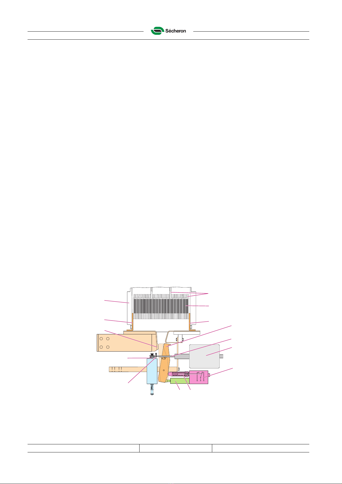
The UR46 is a DC high-speed current-limiting circuit-breaker, with natural cooling. It has been
designed to ensure, on detection of a short-circuit, a trip free and rapid opening of its main
contact; and to quickly extinguish the arc by generating a constant over-voltage during the whole
interruption process.
04601
1. Fixed insulating frame made of glass-fibre reinforced insulating material.
2. Main circuit, consisting of a lower connection terminal (21), a moving contact (22), an upper
connection terminal (23) and a fixed contact (24).
3. Over-current release.
4. Arc chute.
5. Closing device and fork.
6. Auxiliary contacts housing with pusher (7).
8. Coolers
A.1.2 Uses of the high speed circuit-breaker
Because of its short response time following the detection of an excess current (short-circuit,
overload detection...), it is particularly suitable for the protection of the DC equipment in traction
substations or industrial installations.
DANGER!
To ensure maximum safety, servicemen and operators must read the A.2 "Safety
precautions" section before starting installation, maintenance and adjustment of
the device or before starting to operate it.
8
1
23
21
22
24
3
7
4
5
6
2
Secheron
▲
\m
v-^ o o
\
o o
msm
i^-. 33 u
XL
\
Introduction UR46-81/82S
Document number: SG104148TEN Revision: B01 Issue date: 20.8.2012
Copyright© 2012 Sécheron SA - This document is not contractual and contains information corresponding to the level of technology at the date of release.
A-10 File: a-UR46-8S_Intr_en.fm
A.1.3 Main features
• High insulation level to earth and between main contact
• High breaking and making capacity
• Long service life
• Simple maintenance
• Small dimensions
A.1.4 Functions
Closing
When a closing pulse is received, the closing device (1) moves the fork (2), which closes the
moving contact (3) and applies the contact pressure to the main contacts (3 & 9). The pusher (4),
pushed by the moving contact (3), actuates the auxiliary contacts (5). The closing force is
absorbed by the shock absorber (6).
Holding
Once the main contact is closed, the contact pressure is maintained by the closing device (1),
either with a reduced holding current (E type) or with a permanent magnet (M type).
Opening
The circuit-breaker opens either through an over-current release or through an appropriate
opening order:
• An over-current that exceeds the maximum current setting value, causes the direct release
rod (7) to move up, which lifts (8) the fork (2), thus releasing the moving contact (3).
• Opening the breaker on remote order cuts off the holding current of the closing device
(E type) or applies a reverse current pulse (M type), which causes the fork (2) to retract.
The pusher (4) then opens the moving contact (3) and actuates the auxiliary contacts (5).
The arc generated between the main contacts (3 & 9) moves upwards between the horns (11)
into the arc chute (10) and is split by the baffles (12). The ionized gases are mostly neutralised
between the de-ionizing plates (13).
03649-S
1
2
3
12
11
13
5
4
6
7
8
11
10
9
1^21 Secheron
mm
[r
o o1
o o□
rrrr 3
or" p
Hrf
\
Document number: SG104148TEN Revision: B01 Issue date: 20.8.2012
Copyright© 2012 Sécheron SA - This document is not contractual and contains information corresponding to the level of technology at the date of release.
File: a-UR46-8S_Intr_en.fm A-11
UR46-81/82S Introduction
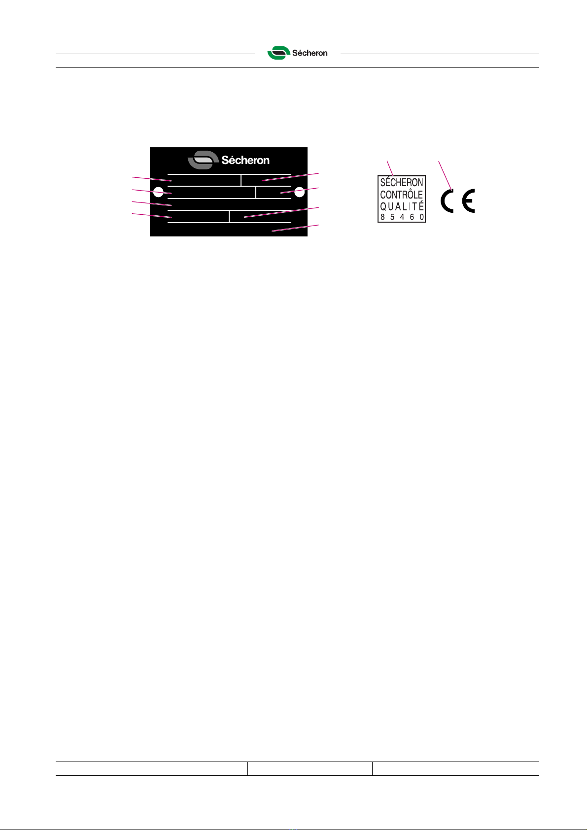
A.1.5 Device identification
The plate that is riveted to the device carries the data should you need to contact Sécheron.
The CE mark indicates that this device complies with the basic health and safety regulations of
the European Economic Area (EEA).
03653
A.1.6 Routine tests
These tests define the particular characteristics that each device has to fulfil at the end of the
production. These values are recorded in a routine test sheet, which is attached to the device at
delivery.
1. Device type 6. International standards number
2. Identification number 7. Rated voltage
3. Serial number 8. Manufacturer, site of manufacture
4. Rated operational current 9. Routine test certificate
5. Manufacture date 10.CE mark
Type:
Nr: IEC/EN
Sécheron SA, Genève
Ser. Nr:
In: Un:
Date
10
9
1
2
3
4
5
6
7
8
Secheron
Secheron
SECHERON
CONTROLE
Q ALITE
8 5 4 6 0
Introduction UR46-81/82S
Document number: SG104148TEN Revision: B01 Issue date: 20.8.2012
Copyright© 2012 Sécheron SA - This document is not contractual and contains information corresponding to the level of technology at the date of release.
A-12 File: a-UR46-8S_Intr_en.fm
A.2 Safety precautions
A.2.1 General precautions
A.2.2 Safety requirements for the installation
of electric equipment connected to a Sécheron’s circuit-breaker mounted on a vehicle.
When mounting electrical equipment inside a vehicle, the consequences of an eventual fault in
the circuit breaking of the Sécheron’s circuit-breaker must absolutely be taken into account.
All the necessary precautions must be taken in order to ensure the safety of the people inside
(and/or outside) the vehicle if such a fault happens. Sécheron declines any responsibility in the
case of non respect of the directive EN 45545.
DANGER!
High voltage electricity can kill or cause serious injury.
Never touch the circuit-breaker before the high voltage circuit is neutralized and the
installation is properly earthed.
All inspection, maintenance and installation operations carried out on the circuit-
breaker must be performed with the power off and the circuit-breaker earthed.
Some controls require the use of low voltage (DC) electrical supply. Follow the
safety requirements in force to carry out these operations.
When performing installation, inspections and maintenance, keep your hands away
from moving parts during the opening and closing operations of the circuit-breaker.
Do not attempt to service the internal parts without the presence of another person
who is trained in first aid.
Modifying, removing, deactivating or otherwise changing components in any way
may affect the safety of the device. Not using parts from the original manufacturer
can affect the performance and safety of the device and automatically waives
Sécheron’s warranty
A circuit-breaker that appears to be damaged or defective should be disconnected
or made inoperative and secured against unintended operation until they can be
repaired by qualified personnel.
When isolating electrical equipment, the following five safety rules have to be
observed: disconnect from the power supply / take the necessary means to prevent
reclosing of the isolating switches / test absence of voltage by approved means /
ensure earthing and short-circuiting by approved means / protect adjacent live
parts by covers and barriers and fit a suitable warning notice.
Secheron
A

Document number: SG104148TEN Revision: B01 Issue date: 20.8.2012
Copyright© 2012 Sécheron SA - This document is not contractual and contains information corresponding to the level of technology at the date of release.
File: a-UR46-8S_Intr_en.fm A-13
UR46-81/82S Introduction
A.2.3 Hazard information
Hazard information in this document has the following meanings:
A.2.4 Personnel use requirements
The instruction manual describes the authorized ways to install, operate and service the
device, and it may only be installed, operated and serviced in accordance with these instructions.
Sécheron will take no responsibility for injury or damage if the device is installed, operated and
serviced in any other way.
During installation, maintenance and operation of the device, technicians and operators are
responsible for:
• the device and the working area around the device;
• the personnel in the device area;
• ensuring that the safety test is fully completed before the high voltage circuit is connected.
Electricians should be certified according to local regulations with experience of similar types of
installations. They must have proven skills in reading and working with drawings and cable lists,
as well as knowledge of local safety regulations for power and automation. Work with the elec-
trical equipment must be performed by skilled or instructed technicians only.
• A skilled person is an individual with technical knowledge or sufficient experience enabling
him to avoid the hazards that electricity/mechanical devices/chemicals etc. can create.
• An instructed person is an individual adequately advised or supervised by a skilled person, in
order to avoid the hazards that electricity/mechanical devices/chemicals etc. can create.
DANGER!
Immediate danger to life!
Failure to observe this information will result in death or serious personal injury!
WARNING!
Risk of serious personal injury!
Failure to observe this information could result in death or serious personal injury!
CAUTION!
Risk of minor personal injury!
Failure to observe this information may result in minor personal injury!
Important!
Risk of damage to equipment!
Failure to observe this information could result in damage to equipment
WARNING!
If safety precautions are not followed, there is risk of personal injury.
Secheron
A\
A\
A\
A\
▲I

Introduction UR46-81/82S
Document number: SG104148TEN Revision: B01 Issue date: 20.8.2012
Copyright© 2012 Sécheron SA - This document is not contractual and contains information corresponding to the level of technology at the date of release.
A-14 File: a-UR46-8S_Intr_en.fm
This page intentionally left blank
Secheron

UR46-81/82S Technical specifications
Document number: SG104148TEN Revision: B01 Issue date: 20.8.2012
Copyright© 2012 Sécheron SA - This document is not contractual and contains information corresponding to the level of technology at the date of release.
File: b-UR46-8S_tech data_en.fm B-15
B. Technical specifications
B.1 Characteristics
B.1.1 Breaking current parameters
Iss = Prospective sustained short circuit current
Îss = Peak of Iss
Icut off = Cut off current
Id= Setting of maximum current release
di/dt = Initial current rate of rise
UNe = Rated voltage
Ûarc = Maximum arc voltage
tb= Total break time
tc= Time-constant of the circuit
tl= Opening time
B.1.2 Main circuit
Refer to the corresponding data sheet for complementary information.
B.1.3 Control circuit
B.1.4 Operating conditions
Unit UR46-81S UR46-82S
Rated voltage UNe 900 V 1800 V
Maximum operational voltage 1000 V 2000 V
Rated insulation voltage UNm 3000 V 3000 V
Rated service current INe 4600 A 4600 A
Conventional free air thermal current (Tamb=40 °C) Ith 4600 A 4600 A
Rated short-circuit making and breaking capacity according
to EN-50123-1-2
ÎNss
INss
TNc
180 kA
125 kA
100 ms
115 kA
80 kA
31.5 ms
Maximum arc voltage Ûarc ≤2500 V ≤4000 V
Nominal voltage Un24, 36, 48, 72, 96, 110, 220 Vdc
Supply voltage limits (-25°C < Tamb < +40°C) 0.7Unto 1.25Un
03659_S
Id
Icut off
Iss
0.63 Iss
U
t
t
tl
I
tb
Îss
di/dt
Ûarc
UNe
t
c
Ambient outdoors temperature Tamb -25 °C to +40 °C
Altitude h ≤1400 m
Flammability To standards NF F 16-101 - NF F 16-102 – NF ISO 1928
Secheron
s
~T
/
/
/
/
/
/
/A
/
/
VVWVN

Technical specifications UR46-81/82S
Document number: SG104148TEN Revision: B01 Issue date: 20.8.2012
Copyright© 2012 Sécheron SA - This document is not contractual and contains information corresponding to the level of technology at the date of release.
B-16 File: b-UR46-8S_tech data_en.fm
B.2 Breaker control
The circuit-breaker can be maintained in the closed position using either a reduced holding
current (E type) or without current (M type).
Note! Sécheron recommends the protection of the closing device coil using an automatic circuit-
breaker with thermal protection, having the following characteristics: a closing pulse duration of
0.5-1 sec, the ability to trigger the circuit-breaker several times consecutively and a holding
current that is limited to 5% of the closing current.
Electric holding: E type
A. Start of the closing pulse: the contacts F + G close.
B. Closing pulse: 0.5 to 1 s.
C. Start of the holding current: the contact G opens.
D. Holding: a R1 resistance limits the holding current to 5% of the closing current.
E. Opening: the contact F opens to provoke the interruption of the holding current.
03602
Magnetic holding: M type
A. Start of the closing pulse: the contacts E close.
B. Closing pulse: 0.5 to 1 s, then the contacts E open.
C. Holding: achieved by the permanent magnet.
D. Opening: the contacts F close to provoke a current pulse of the opposite polarity to the
closing current. The duration of this pulse is 0.5-1 s, then the contacts F opens. The opening
current is 20 % of the closing current.
03604
Important!
A longer closing pulse may burn the coil.
R1: holding resistor S: automatic circuit-breaker
Rp: parallel resistor Rs: serial resistor S: automatic circuit-breaker
–
+
~ 5%
100%
00,5 1 t [s]
S
V=
R1
E
F
G
B C
AD
Ie
Ie
~ 20%
100%
0
0
0,5 1 tctc+1
tc+0.5
t [s]
D
FE
B
AC
–
S
V=
+
Rp
Rs
1^21 Secheron
Al
oo o o o:
o
ae
oa
o o o
iI
QQ
\
Document number: SG104148TEN Revision: B01 Issue date: 20.8.2012
Copyright© 2012 Sécheron SA - This document is not contractual and contains information corresponding to the level of technology at the date of release.
File: b-UR46-8S_tech data_en.fm B-17
UR46-81/82S Technical specifications
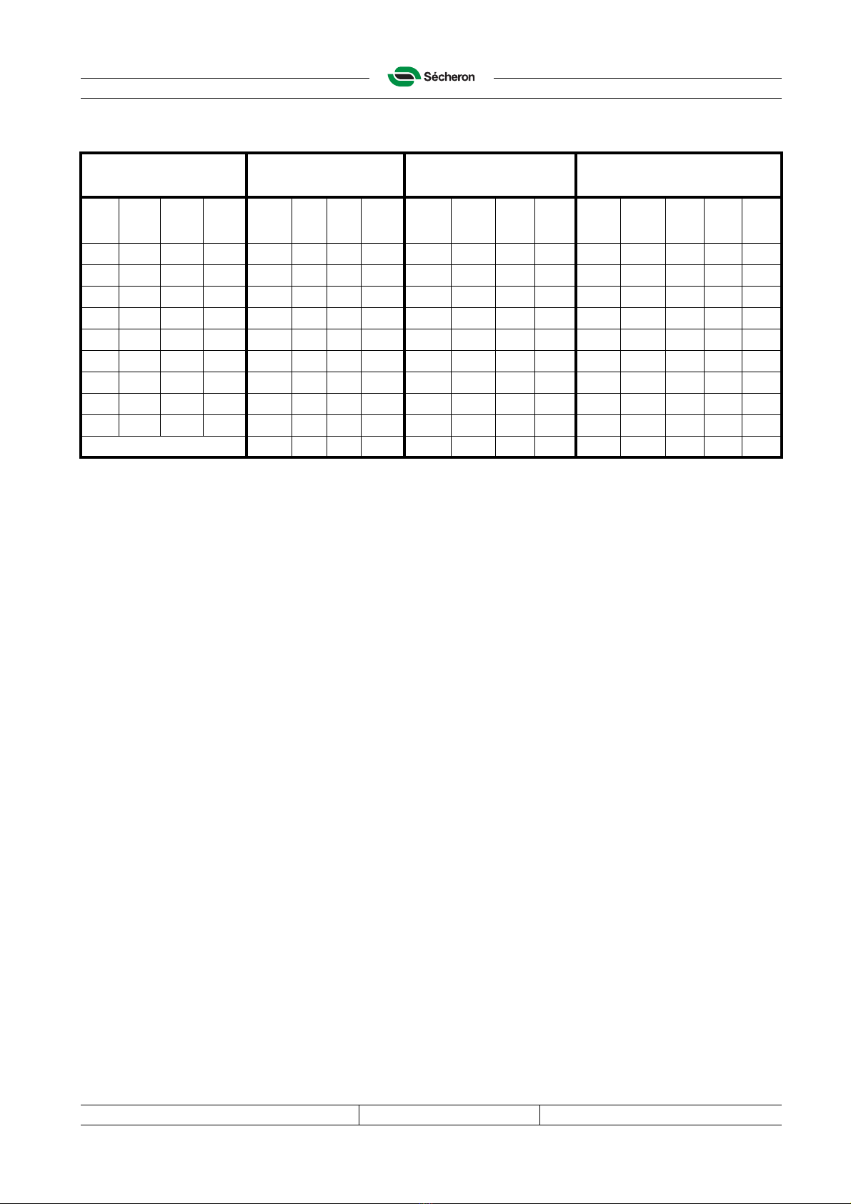
B.2.1 Typical values for the closing coils
* Optional voltage
R1: resistor to be inserted in the holding circuit of the E type; the power to be considered for the
resistor choice is 220 W (4x55 W).
Rs: resistor to be inserted in serial with the coil in the opening circuit of the M type; the power to
be considered for the resistor choice is 50 W (200 W / 4).
Rp: resistor to be inserted in parallel with the closing coil in the opening circuit of the M type.
Notes
• Values given for ambient temperature range between -30°C and 70°C. The Imax and Imin
values are given for the most unfavourable values of voltage and temperature.
•R
min = 0.92 x Rnom; Rmax = 1.08 x Rnom.
• These values refer to DC voltage or rectified full-wave voltage.
• The total opening time with a recovery diode is 2.5 s (not recommended as the opening time
is too long).
• Sécheron recommends to protect the control circuit (while opening) with a varistor.
Coil characteristics Closing E type holding M type opening
Pulse 0,5 to 1 [s] Pulse 0,5 to 1 [s]
Unom
Umin
Umax
Rnom
Inom
Imin E
Imin M
Imax
R1
Inom
Imin
Imax
Rs
Rp
Inom
Imin
Imax
[V] [V] [V] [Ω] [A] [A] [A] [A] [Ω] [A] [A] [A] [Ω][Ω] [A] [A] [A]
24 16.8 30.0 0.575 41.7 22.5 25.0 70.9 11.4 2.00 1.38 2.54 2.36 1.33 6.07 3.81 8.49
36 25.2 45.0 1.10 32.7 17.7 19.6 55.6 25.0 1.38 0.95 1.74 5.30 2.99 4.31 2.73 5.96
48 33.6 60.0 2.30 20.9 11.3 12.5 35.4 45.7 1.00 0.69 1.27 9.40 5.35 3.05 1.90 4.27
64* 44.8 80.0 3.64 17.6 9.5 10.6 29.9 79.4 0.77 0.53 0.97 17.20 9.00 2.30 1.45 3.20
72 50.4 90.0 4.40 16.4 8.8 9.8 27.8 100.0 0.69 0.48 0.87 21.20 11.97 2.16 1.36 2.98
110 77.0 137.5 9.40 11.7 6.3 7.0 19.9 210.0 0.50 0.35 0.63 40.00 20.00 1.61 1.01 2.26
125* 87.5 156.3 11.95 10.5 5.6 6.3 17.8 272.0 0.44 0.30 0.56 52.00 26.00 1.42 0.89 1.99
220 154.0 275.0 37.60 5.9 3.2 3.5 9.9 840.0 0.25 0.17 0.32 160.0 80.00 0.81 0.50 1.13
Power consumption [W] 1300 400 400 2200 55 2.3 1.2 3.6 200 15 25 12 38
Secheron

Technical specifications UR46-81/82S
Document number: SG104148TEN Revision: B01 Issue date: 20.8.2012
Copyright© 2012 Sécheron SA - This document is not contractual and contains information corresponding to the level of technology at the date of release.
B-18 File: b-UR46-8S_tech data_en.fm
B.3 Auxiliary contacts
B.3.1 Commutation diagram
03672
M. Main contact
A. Switching of auxiliary contacts (a+b)
Number of auxiliary contacts 5a (NO) + 5b (NC) in standard configura-
tion
Rated voltage (potential free contacts) 24 to 220 Vdc
Maximum breaking current
– Ohmic load at 110 Vdc
– Inductive load τ= 15 ms at 110 Vdc 1 A
0.3 A
Conventional thermal current Ith 10 A
Minimum let-through current at 24 Vdc
(For a dry and clean environment) 10 mA for silver contact;
4 mA for gold contacts.
Connections M3 screws
M
Ab (3-4)
a (1-2)
1
0
1^21 Secheron
Jcl^Slc <k | v k
T T
t
UR46-81/82S Installation
Document number: SG104148TEN Revision: B01 Issue date: 20.8.2012
Copyright© 2012 Sécheron SA - This document is not contractual and contains information corresponding to the level of technology at the date of release.
File: c-UR46-8S_inst_en.fm C-19
C. Installation
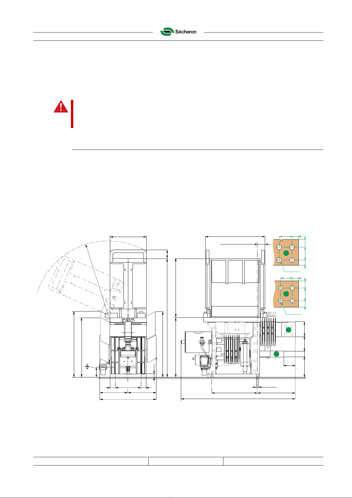
C.1 Weight and dimensions
Dimensions
The DIN-ISO 2768-1 coarse tolerances are applied to these dimensions.
04610-S
(1) Type 81 arc chute
(2) Type 82 arc chute
DANGER!
To ensure maximum safety, servicemen and operators must read the A.2 "Safety
precautions" section before starting installation, maintenance and adjustment of
the device or before starting to operate it.
Weight (± 5 kg) UR46-81S UR46-82S
Circuit-breaker (standard, without options):85kg 86 kg
Arc chute:25 kg 34 kg
Total:110 kg 120 kg
320 246
70
760
4xØ11
23
62
69 (1) / 168 (2)
419 (1) / 617.5 (2)238
100
40
137 40 95
386
437
397(1)
398
784 51
100
40 40160
378
==
437(2)
R490
4x Ø18
25
50
25
50 25
305020
40 25
4x Ø16
B
A
A
B
Secheron
A
t
r
XT
- l -©-
'7
///a
' V / /' p:=
/l-
/i*",
/ ":<7■4)—(b—z
t, P //
/-V
73C
ip [°L
liiifl
Q-O
Ojo o
Q0J0
o
1Z ■o
«o o
n
oo
o■n-
ty uo
°?
m'D-H o
#■ JZL
J
'
-
Installation UR46-81/82S
Document number: SG104148TEN Revision: B01 Issue date: 20.8.2012
Copyright© 2012 Sécheron SA - This document is not contractual and contains information corresponding to the level of technology at the date of release.
C-20 File: c-UR46-8S_inst_en.fm
C.2 General requirements
Special arrangements must be agreed between the user and Sécheron SA to cover extreme
service conditions such as:
• altitude above 1400 m;
• ambient temperature exceeding + 40°C;
• minimum temperature below - 25°C;
• high average temperature combined with high relative air humidity (> 95%);
• heavy rain, sand storms, etc.
C.3 Delivery check and acceptance
C.3.1 Check
The customer must open the package and visually check:
• the conformity of the delivered devices with the order: correct identification numbers on the
identification plates and correct number of devices;
• for any damage on devices.
C.3.2 Transport damage procedure
If the equipment is damaged, the customer must imperatively report the damage by an official
letter to Sécheron SA within 7 days after receiving the goods. Once this delay has expired, all
transport damages can no longer be covered by Sécheron SA. Sécheron SA will have to charge
the customer for any repair. For the repair procedure, please refer to our website
“www.secheron.com” and click on “Services / RMA”.
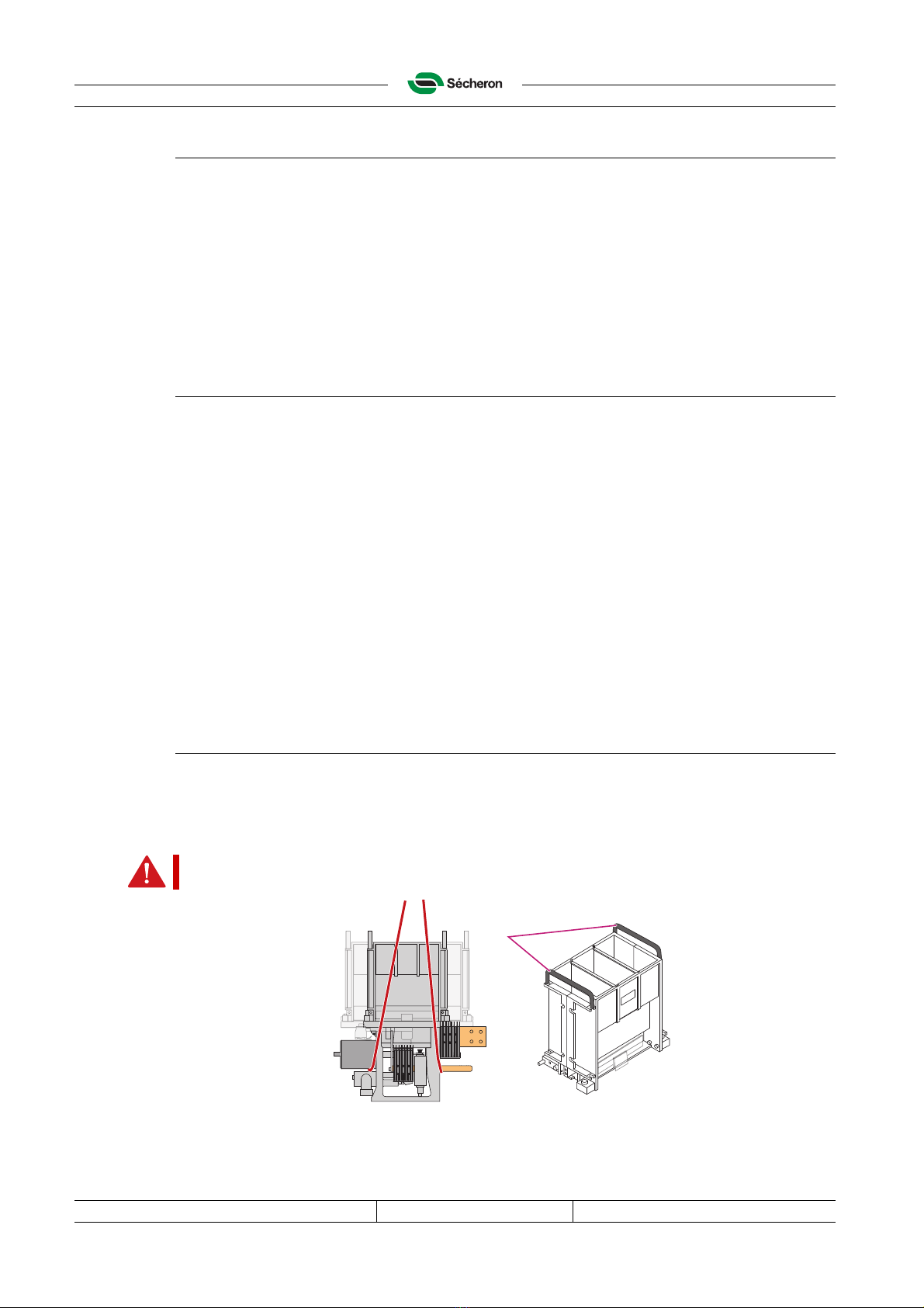
C.4 Handling
Circuit-breaker with its arc chute attached: lift it using ropes/slings as shown below.
Arc chute only: manipulate it by hand, or ropes, or straps and a hook. Lift the arc chute using
both lifting handles (1).
04611-S
CAUTION! Risk of crushing.
The high speed circuit-breaker can weight up to 120 kg.
1
1^21 Secheron
Al
3
^ /[ o o
T
This manual suits for next models
1
Table of contents


