ENFORCER SLI 820R/-4 Tech Manual
SECO-LARM U.S.A., Inc.
Page 8
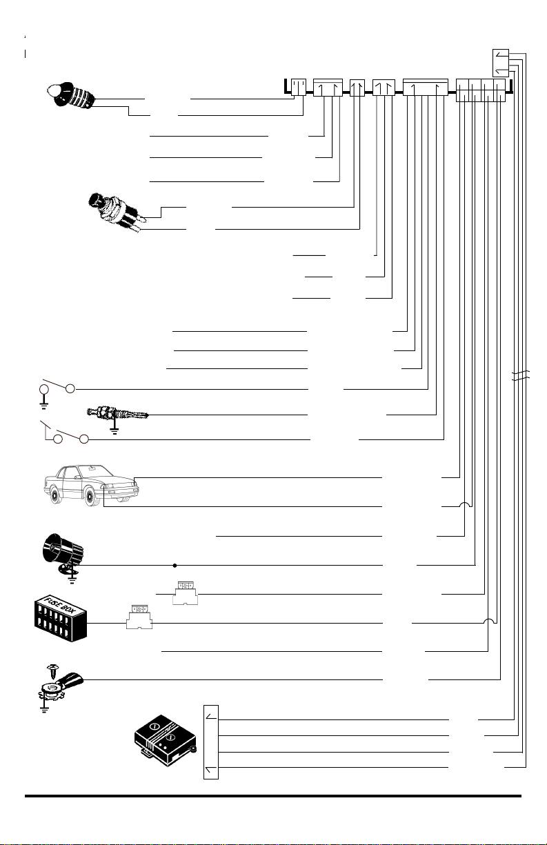
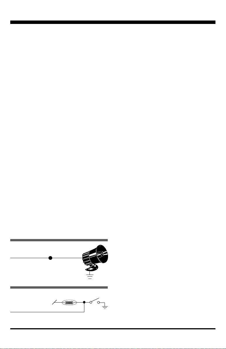
Siren BLACK wire (ground)
Siren RED wire
(siren +12V input)
Alarm PINK wire
(Siren +12V output,
2A max.)
Ø
Fig. 4 Connecting to the siren
B. Connect the sirens BLACK WI E directly to
the vehicles metal chassis. Scrape paint
from the metal surface, and use a factory
grounding bolt or a star washer.
C. Connect the alarms PINK WI E directly to
the sirens ED WI E.
Connector 2 (8-pin connector)
YELLOW WIRE (to ignition switch
oltage input)
Connect to a fuse or wire which outputs
+12VDC when the ignition key is in the ON and
STA T position, but not the ACC position. This
wire must be connected at all times to ensure
proper arming and disarming, as well as to
operate the VEPLe push-button switch.
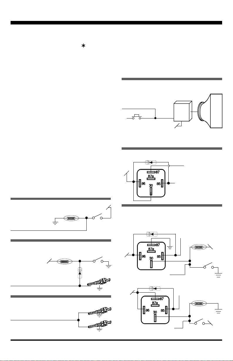
Connector 3 (6-pin connector)
BLUE WIRE (neg. door trigger input),
fig. 5
A. Existing car door switches Use a VOM
meter to locate a wire (usually in the drivers
kick panel) which shows ground when any
door is open, and which is not ground when
all the doors are closed. Connect to the
BLUE WI E. (NOTE If this wire shows
+12VDC when a door is opened, see
PU PLE WI E below.)
B. If the vehicle (such as a delivery van) has no
existing car door switches Mount a pin
switch in every door you wish to protect.
Connect each switch to the BLUE WI E.
Connector 3 (6-pin connector)
PURPLE WIRE (pos. door trigger input),
fig. 6
Use a VOM meter to locate a wire (usually in the
drivers kick panel) which shows +12VDC when
any vehicle door is open, and which is not
+12VDC when all the doors are closed.
Connect to the PU PLE WI E.
Connector 3 (6-pin connector)
BLUE/WHITE WIRE (negati e hood/
trunk trigger input), figs. 7 & 8
A. If the vehicle has a trunk switch, but no hood
switch Use a VOM meter to locate the wire
which shows ground when the trunk is open,
and which is not ground when the trunk is
closed. Mount a pin switch in the hood.
Connect both to the BLUE/WHITE WI E as
shown in fig. 7.
B. If the vehicle has no existing hood or trunk
switches Mount a pin switch in both the
hood and the trunk. Connect both switches
to the BLUE/WHITE WI E as shown in fig. 8.
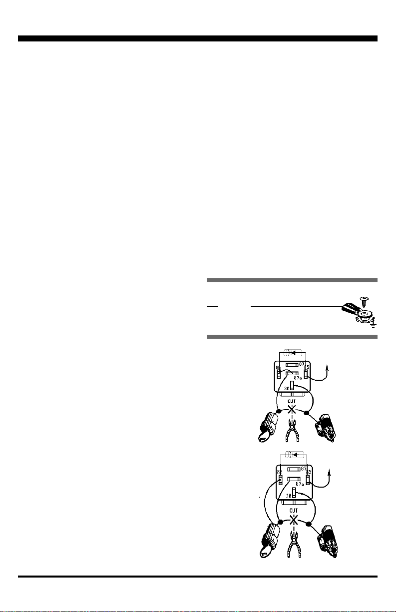
Connector 3 (6-pin connector)
BROWN/WHITE WIRE ( (-) factory
honking horn output), fig. 9
Programmable - Supplies a pulsing 200mA
output to drive a (-) factory car horn relay.
A. Operation - When the alarm is triggered, this
wire pulses 200mA to activate the (-) factory
horn honk relay found in most vehicles. This
allows the alarm to honk the horns and blast
the siren at the same time.
B. Connection - Connect the B OWN/WHITE
WI E directly to the negative input of the
vehicles factory horn relay (it should show
() when the vehicles horn button is
pressed). Make sure this input draws less
than 200mA of current. Otherwise, add a
30A relay to honk the horns.
Connector 3 (6-pin connector)
BLACK/WHITE WIRE (2nd ch. output),
fig. 10
Note -- 2nd channel output works only if the
optional ENFO CE remotes are used.
Domelig t
+12VDC
×Alarm BLUE wire (neg. door trigger input)
Door
switc
Fig. 5 Connecting to negative door
triggers