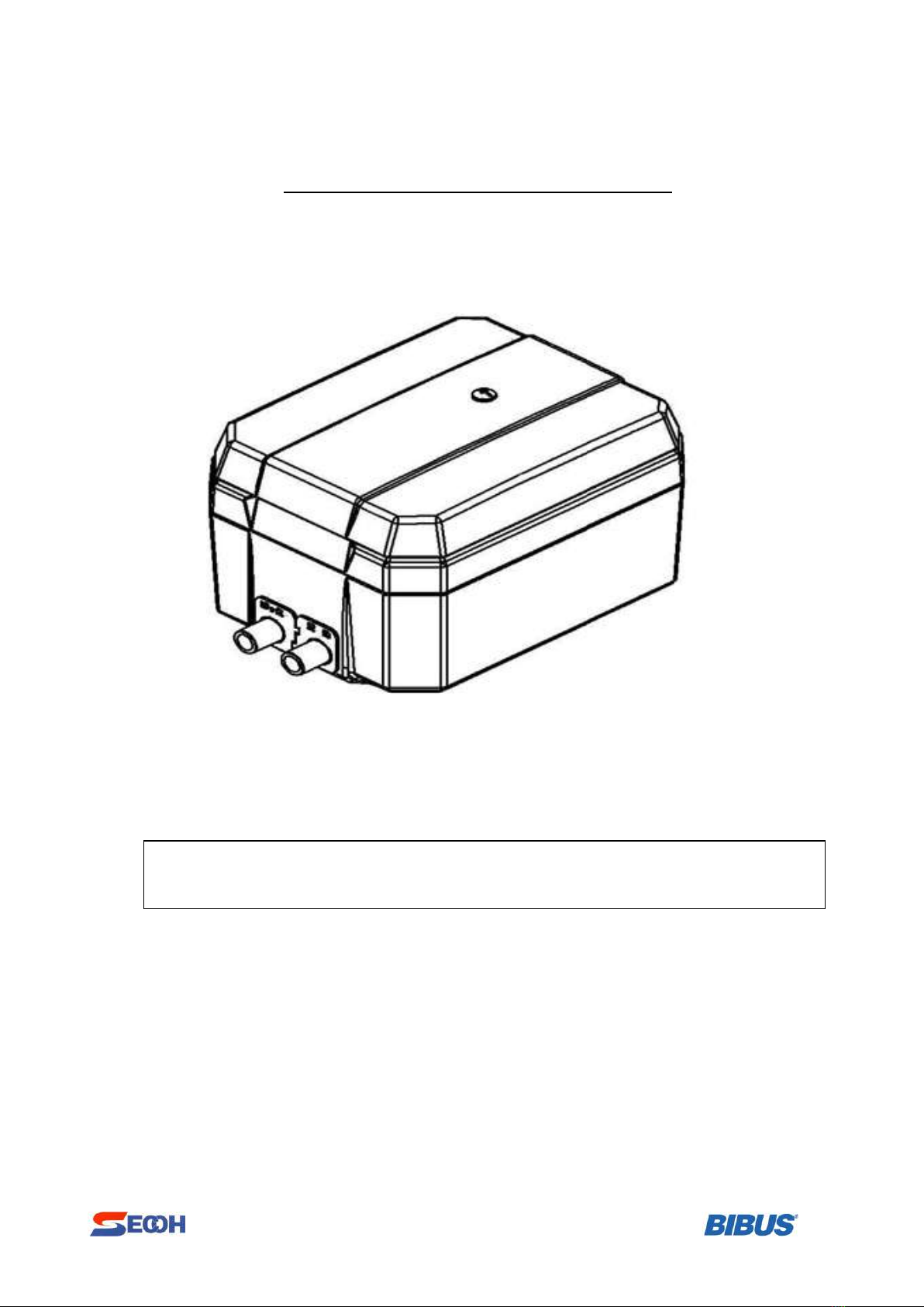
Secoh JDK-60T User manual


This manual suits for next models
2
Other Secoh Water Pump manuals


Popular Water Pump manuals by other brands

Grundfos
Grundfos Hydro Multi-B instructions

Zwilling
Zwilling Fresh & Save Vacuum Storage System operating instructions

GORMAN-RUPP
GORMAN-RUPP S Series MAINTENANCE AND REPAIR WITH TROUBLESHOOTING

Talon
Talon TP-72S manual

EINHELL
EINHELL ROYAL TDM 1000-S operating instructions

Becker
Becker VX 4.16 operating instructions

Espa
Espa CKE Series instruction manual

Grundfos
Grundfos AP80-100 Safety instructions and other important information

Ashland
Ashland EPF30 OPERATION, PERFORMANCE, SPECIFICATIONS and PARTS MANUAL

Wilo
Wilo Helix EXCEL 1004-2/25/V/KS,DN40,2.2kW Installation and operating instructions

Pentair
Pentair JUNG PUMPEN BAUFIX 100 instruction manual

Walrus
Walrus HQ800 Replacing

FUXTEC
FUXTEC FX-WP152 Original user manual

Lorentz
Lorentz PSk Series MANUAL FOR INSTALLATION, OPERATION, SERVICE

Wilo
Wilo PB BOOST FIRST Installation and operating instructions

MATO
MATO pneuMATO-fill operating instructions

Zoeller
Zoeller 1261-0001 manual

teel
teel 4RJ47 Operating instructions & parts manual