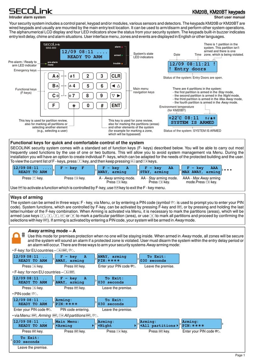
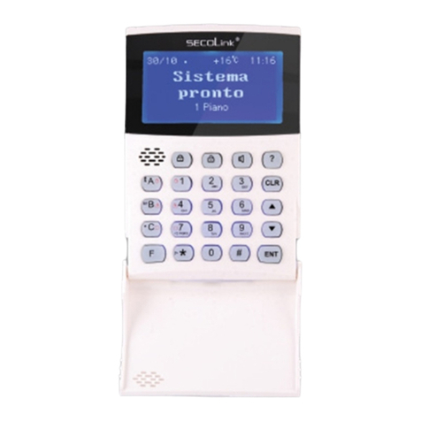
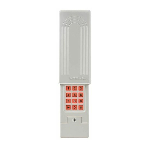
SECOLink KM20B Owner's manual

Short programming manual is recommended for professional installers who are experienced in the installation of intruder alarm
systems and have already read the SECOLINK wiring manual. The wiring manual must be read before the installation to avoid
accidents with high voltage and temperature.
SAFETY WARNINGS
The device must be connected to AC power supply with Protective Earthing. Cable colour and purpose: Phase or Live line (L) - black or
brown cable, Neutral line (N) - blue cable, Protective Earth line (PE) - green cable with a vertical yellow stripe. Only double isolated cables
2
with cross-sectional area of no less than 0,75 mm shall be used for 230V power supply.
Additional automatic two-pole circuit breaker should be installed in AC electric power circuit in order to prevent over-current and short
circuits. The circuit breaker should be placed close to the system's housing and should be easily reached. Full shutdown could be done by
turning off 230V AC main power supply with automatic two-pole circuit breaker and by disconnecting the battery. Before performing any
installation work or maintenance ALWAYS disconnect the device from the power supply.
DEFAULT TEMPLATE
STARTING THE SYSTEM WITH A SINGLE KEYPAD
The system is shipped from the factory with specific default values (further default template) suitable for a typical installation. If the default
template is suitable for your installation, then programming can be simplified. If template is not suitable for your instalation, then you can
easily customize this default template with the software MASCAD. Download MASCAD at www.secolink.eu prior to installation:
Short programming manual - basic information Intruder alarm system
System with KM20B keypads
Note: the default template can be different for different countries. Check a sticker on the keypad for a
country prefix or pre-installed template code. Example: KM20B_EN.
1.Connect the keypad to your computer using a USB cable (keypad should not be connected to
system data bus).
2. Download default template from the keypad to software MASCAD (use the tab Project data
sending/receiving).
3.Once you customize the predefined template, you can use it to program an individual system or
thousands of systems.
4. DO NOT FORGET to upload the customized template (further project) back to the keypad (use
the tab Project data sending/receiving). Fig. 1 USB connection
Upon power-up of the system, the keypad will display a phrase First Start Press [ENT]. It means that the keypad is ready to run an
automatic module registration procedure and later send the default template (or customized project) to the control panel and all
successfully registered system modules.
Press the [ENT] key. Template is being sent
to the system.
Registration of modules is
in progress.
Entering Service. Leaving Service.
STARTING THE SYSTEM WITH MULTIPLE KEYPADS
No Control Address 00 phrase will display upon power-up of the system with multiple keypads. It means that the keypad has the same
address in the system as the other keypads or modules. Press the [Ü] key on a keypad which will become the primary keypad. The primary
keypad should become the one which has a customized project OR it could be any keypad if the default template is not customized. When
the [Ü] key is pressed the keypad will emit a short audible signal and a phrase First Start Press [ENT] will appear on the screen.
Simply press [ENT] if the primary keypad contains a customized project with precise module addressing. If the primary keypad contains
just a default template, then use keys [1], [2], [3], [4], [5] to manually assign the address to each keypad. When all addresses of the keypads
are assigned, return to the primary keypad and press the [ENT] key. All keypads will be registered according to their addresses, which were
Press the [Ü] key. Primary keypad
Used. Choose another.
Processing ...
Assigned address 02.
Selecting the primary keypad :
Manually assigning addresses to other keypads:
For a small system with a few keypads, it is
recommended to choose addresses of keypads in
01 - 04 range, and for a large system in 01 - 04 and 10
- 15 ranges. This is done ir order to not disturb the
default addresses of other modules with the
addresses of the keypads.
given manually. Note: the keypad will remain
unregistered if you will forget to assign the address.
Page 1
KM20Bx
USB cable
MASC
USB
Computer
First Start
Press [ENT]
Entering Service Registering... From KM20 to CP Leaving Service
Processing...
On the keypad’s LCD :
No Control
Address 00
No Control
Address 00
No Control
Address 02
No Control
Address 03 Used
Processing... First Start
Press [ENT]
DEFAULT ADDRESSES OF THE MODULES
System manufacturer has provided the modules with default addresses assigned to them. This is done in order to simplify the process of
registration for most frequently used combinations of the system modules (such as PAS808M, KM20B, GSV6U or PAS816, KM24A,
EXM800, EXT116S, GSV6U). While registering modules of a different type, you will not need to enter serial numbers of each module, as
the system will automatically assign default addresses for the modules that are listed below:
For all control panels
For the keypad KM20B, KM24, KM25
For the keypad with a temperature sensor KM24A, KM24G
For extra power supply module PWR20
- address 00;
- address 01 or 03;
- address 02 or 04;
- address 04 or none;
Enter the address

ENTERING SERVICE MODE
It is recommended to use the computer and software MASCAD for the installations with few partitions and more than 10 zones. For simple
installations it is more efficient to change the template manually by using the LCD keypad. Changes should be made in service mode when
the system is disarmed.
For security reasons permission to access the service mode has to be enabled by entering the user's PIN (default PIN codes: first user -
0001,service - 0000). There are 2 ways to enter the service mode:
by navigating the menu:
by using the F-key:
Fig. 2 Tab F - keys
There is an option to set the system without entering the required user's PIN that is needed to access the
service mode. To do this, you will need to modify the template by using software MASCAD:
1. Connect the keypad to your computer using a USB cable.
2. Establish a connection with the computer. Using the keys with arrows go to the menu: Service Mode }
Project Loading }Open USB port.
3. Download data from the keypad to software MASCAD (use the tab Project data sending/receiving).
4. Go to tab F-key.
5. Click on row F33 SERVICE Mode and uncheck the box User PIN required from the settings (see Fig. 2).
6. Upload the customized project back to the keypad (use the tab Project data sending/receiving).
MANUAL REGISTRATION OF MODULES
Control panel PAS808M supports up to 7 modules and control panels PAS816, PAS832, P16, P32 supports up to 15
modules. If there are a few modules with same default addresses in the system (for example: several EXM800 or
GSV6U and LAN800 modules), only the module with a greater serial number will be registered during the module
registration procedure. All remaining modules (not registered) must be registered manually.
To register the module, an installer must enter the service mode, type in a 10 digit serial number, which is on the
module’s label (see Fig. 3), then press the [ENT] key to jump to second row, enter module address of the system, and
press [ENT] again to start registration. Fig. 3 EXM800 label
The module will start to flash its address with the green LED after a correct serial number and address is entered. If a mistake was made
while entering serial number, the module will stay unregistered. If a mistake was made while entering the address which is used by another
module, then the new module will overtake this address and the other module will stay unregistered.
Note: a registered module will slowly flash its address on a green LED, which is located on the module's PCB (excluding keypads and a
control panel). If the green LED is steady On it means that the CLK, DAT wires are not correctly connected.
Service Mode } System setup } Modules } Manual registr.
Page 2
Short programming manual - basic information Intruder alarm system
For the zone/PGM expansion module EXM800
For the remote control module EXT016, EXT116S, EXT216
For the proximity reader PROX8
For the GSM/GPRS, LAN communicator GSV6U, GSVU
- address 05;
- address 06;
- address 06;
- address 07 or 11 (for GSVU);
Enable Service:
User PIN:****
Service Mode:
ServicePIN:****
Entering ServiceMain Menu:
Service Mode
F - key F33
SERVICE mode
Enable Service:
User PIN:****
Service Mode:
ServicePIN:****
Entering Service
System Setup:
Modules
Modules:
Manual registr
Registering...SN:3221226047
Address: 6
Service Mode:
System Setup
PARTITIONS
Partitions allow you to break up a large area into smaller sections. This feature is useful to disarm certain areas while leaving other areas
armed, or to limit access of certain areas to other users.
It is recommended to give an appropriate name to a partition. The system will use it when sending SMS or when
showing the status of the partition on keypad's LCD. For next character possition press [|] or [}] key. Move the
cursor on the wrong character to delete it and press [0].
The alarm system can be divided into 4 partitions for operation flexibility. Confirm the activation of a new partition
by selecting Yes. Press [Ü] or [7] key for the next partition.
Exit Delay time is same for all partitions in control panel PAS808M, but it can be different for each partition in
control panels PAS816, PAS832, P16, P32.
In this menu it is possible to assign the timer(s) to partition. Auto-arming starts at a specific time of day and arms
the partition in Stay mode. Auto-arming will be aborted if any of the zones in partition will be violated or trouble
will appear during the exit delay. Use the [ENT] key to access the menu, then press [#] to assign a timer to the
partition. Save changes by pressing the [ENT] key. Note: program system timers in the menu: Main menu }
Settings }Timers).
Service Mode }System Setup }Partitions
P01|Name }
Apartment
P01|In Use }
Yes
P01|Exit Delay }
30 seconds
P01|Timers }
P01 Timers
-Timer 01
|+Timer 02}
System with KM20B keypads

MODULES
Control panel PAS808M support up to 7 modules and control panels PAS816, PAS832, P16, P32 supports up to 15 modules.
Service Mode }System Setup }Modules } Settings
It is recommended to give an appropriate name to module. The module name will appear on keypad’s LCD if
there will be any trouble with the module.
Registered module address is shown on the upper-left corner of LCD (eg. M00 = 00 address). Please remember
the module address and use it to program zones and PGM outputs.
Registered module type is shown on LCD. Available module types: PAS808M, PAS816, PAS832, P16, P32,
KM20B, KM24, KM24A, KM24G, KM25, EXT016, EXT116S, EXT116VM, EXT216, GSV6U, GSVU, EXM800,
PROX8, PWR20, and LAN800.
Registered module serial number is shown on LCD. If you don't see the module serial number, it means that
module is not registered in the system. See page 2 for more information about manual module registration.
For additional security it’s recommended to use tamper to protect modules. Tamper can be activated by using:
Z6 - on control panels;
Z1 - on EXM800;
back switch - on keypads.
If Use module tamper selected as No, then zones Z6 on control panel and zone Z1 on EXM800 can be used as
regular zone terminals.
Basic settings for all modules:
Extended settings for keypad:
Use the [ENT] key to enter to extended settings menu.
Page 3
Short programming manual - basic information Intruder alarm system
M00|Name }
Control Panel
M00|Type }
PAS832
M00|Serial No. }
805308385
M00|Use Tamper }
Yes
M01|Extend.Sett }
KM24G
Use the [ENT] key to enter to extended settings menu.
M06|Extend.Sett }
PROX8
The keypads have additional keys dedicated for emergency conditions. These can be activated by pressing
both emergency keys at the same time (see user manual). However, in some places like a corridor it is
recommended to disable emergency keys to prevent false alarms.
|Fire Alarm }
|Medical Alarm }
|Panic Alarm }
Yes
No
No
Extended settings for PROX8 module:
This setting is related with entry/exit counting when the module is installed indoors or outdoors. If proximity
reader is installed outdoors, then the entry/exit delay is excluded.
The preferred arming mode will appear as a first option. With preferred arming mode selected correctly the user
will spend less time on arming. Arming mode is indicated by a color of PROX8 LED:
Away - red color;
Night - blue color;
Stay - green color;
Max Away - white color.
Note: if there is a need of only 1 arming mode, program all options with the same arming mode.
The proximity reader has a buzzer for audible notifications wich can be enabled or disabled.
The proximity reader has 3 options on what it must do when the unknown proximity tag is detected:
No action
Indication - module starts blinking red and starts emitting an annoying noise.
Indicat.&Alarm - module starts blinking red and starts emitting an annoying noise. The alarm siren will be
triggered after 3 attempts to control the system with an unknown tag.
The proximity reader can be programmed to indicate the present status of the system on LED for a short period
of time when the tag is near a sensitive area of the module or it can indicate the status continuously.
All partitions are usually assigned to the keypad by default. All events related to all partitions are shown on
keypad LCD. If there is a need to monitor only one of all enabled partitions, then assign this partition to the
keypad. Use [ENT] key to enter to menu, then press [#] key to assign partition to the keypad. Save changes by
pressing the [ENT] key.
All partitions by default are usually assigned to the proximity reader PROX8. All events related to all partitions
are shown on proximity reader's LED. If there is a need to monitor only one of all enabled partitions, then assign
this particular partition to the proximity reader. Use [ENT] to enter the menu, then press the [#] key to assign a
partition to the keypad. Save changes by pressing the [ENT] key.
|Partitions }
|Partitions }
+Partition 01
+Partition 01
|Sound }
No
|HideStatusIndi }
No
|Unknown tag }
No Action
|Installation }
Outdoor
|Preferred mode }
|Second mode }
|Third mode }
|Fourth mode }
Away
Night
Stay
Max Away
System with KM20B keypads

ZONE PROGRAMMING
Zones, in the context of an alarm system, are individual detectors. If the alarm gets triggered, the system records the zones that were
tripped, allowing the user to know the exact point of action. Zones also help the monitoring station to know whether they should call the
police or fire department upon an alarm. Each zone must be assigned to a partition.
Service Mode }System Setup }Zones
It is recommended to give an appropriate name to the zone. This name will be used by the system for SMS
sending or for display on keypad’s LCD screen and etc.
Page 4
Short programming manual - basic information Intruder alarm system
|Operation mode }
Small System
The meaning of LED indication depends on module operation mode:
Small System (up to 3 partitions) - this operation mode is useful when the system has 1 or 2 partitions
enabled.
1st and 2nd module LED indicates the arming mode in 1st and 2nd partitions respectively;
3rd LED indicates system troubles;
4th LED indicates an alarm, an alarm memory, not ready status (open zones), and zone bypass.
If the system has 3 partitions enabled, then the 3rd LED will indicate the arming mode of the 3rd partition.
Troubles will be indicated on the 4th LED. Color meaning:
Red color - Alarm;
Red slowly blinking - Alarm memory;
Green color - Not Ready;
Yellow color - Trouble;
Blue color - Bypassed Zone.
Large System (4 partitions) - each partition is assigned to the different module’s LED. Module LED indicates
all information (arming mode, alarm, alarm memory, troubles, and zone bypass).
Z01|Name }
Entry Door
Z01|Address }
Z01|Address }
Z01|Address }
00_1
00_1 A
00_1 B
Z01|Loop Type }
NC/DEOL
Z01|Partition }
1
Z01|Definition }
Entry/Exit
Zone address is a 3-digit number represented in MA_Z format, where MA specifies a module address in the
system and Z specifies a zone terminal in the module board. Example: 00_1 - where 00 means the control panel
and 1 means the zone terminal Z1. To program a doubled zone - A and B detectors must be specified. Use
keypad keys [A] or [B] to specify theses detectors in zone address field (example: 00_1 A, 00_1 B, ...).
Note: use loop types NO/DEOL or NC/DEOL for the doubled zones.
For wireless zones MA_1 – MA_8 the system will automatically assign NO/DEOL loop type and for wireless
zones MA_9 – MA_16 the Vibration loop type. Do not change the loop type of zone!
Wireless module address:
EXT116S - address 06 (default) or one that is given during the registration process.
Virtual wireless module EXT116S address:
P16 - address 12;
P32 - address 12 and 13.
The Loop type menu enables you to program the connection type used for each of the system’s zones. The
actual (physical) loop type for each zone must comply with that selected in the Loop type menu. Available loop
types:
Not used
NC - uses normally closed contacts and no end of line resistor;
NO - uses normally open contacts and no end of line resistor;
uses normally closed (NC) contacts in a zone terminated by a 1k end of line resistor;NC/EOL -
uses normally open (NO) contacts in a zone terminated by a 1k end of line resistor;NO/EOL -
uses normally closed (NC) contacts in a zone using at least two 1k end of line resistors to NC/DEOL -
distinguish between alarms and tamper conditions;
ses normally open (NO) contacts in a zone using at least two 1k end of line resistors to NO/DEOL - u
distinguish between alarms and tamper conditions;
Vibration - special purpose zone loop type;
Roller - special purpose zone loop type;
Each zone must be assigned to a partition. All zones are assigned to the 1st partition by default.
Setting the zone definition is partly determined by the arming mode:
Entry/Exit - used for Entry/Exit doors. A zone must be closed during arming and when the delay expires.
Entry delay will be available when the system is armed in Away or Stay mode.
Interior - usually assigned to motion detectors and to interior doors. Violation of this zone will not trigger an
alarm when the system is armed in Night or Stay mode.
Perimeter or Instant - usually intended for non-exit/entry doors, window protection, shock detection, and
motion detectors. A zone goes immediately into an alarm state when violated while armed.
24h Burglary - a violation of such a zone causes an instant intrusion alarm, regardless of the system’s state.
24h Panic Silent - used for external panic buttons. If violated, an immediate panic alarm is triggered, with the
exception that there is no audible indication of the violation.
24h Panic Audible - same as Panic Silent, except that the alarm will be audible.
24h Tamper - the tamper function is continuously operational. When a 24h tamper zone is activated, a
tamper alarm is generated.
24h Fire or 24h Smoke - for smoke or other types of fire detectors. To avoid false alarms, zone attribute Fire
Verification is recommended to use.
24h Fire button - for external auxiliary emergency alert buttons. If violated, an immediate fire alarm will
sound, regardless of the system’s state.
24h Medical button - for external auxiliary emergency alert buttons. If violated, an immediate medical alarm
will sound, regardless of the system’s state.
System with KM20B keypads

Note: if wireless detectors are in use, this field also specifies how often the system checks for supervision
signals, identifying each of the system’s wireless detectors. The system generates a local trouble signal
identifying the zone of any wireless detectors from which a signal is not received during the specified interval.
Control panel then sends the supervision report code to the CMS.
0,0 seconds - supervision is disabled;
0,1 seconds - 1h supervision window;
0,2 seconds - 2h supervision window;
...
2,4 seconds - 24h supervision window;
2,5 seconds - 25h supervision window;
Note: it is recommended to set the supervision time to a minimum of 2 hours if SECOLINK detectors are in use.
Page 5
Short programming manual - basic information Intruder alarm system
24h Fire supervisory, 24h Low Water Level, 24h RF Jam, 24h Gas Detected, 24h Water leakage, 24h High
Temperature, 24h Low Temperature - this group of definitions is used for the 24h technical zones to report about
abnormalities in the environment.
Control - zone is mostly used to arm/disarm the system (Key-switch zone). Momentary and maintained key-
switch arming are available. This definition can also be used to turn On / Off the PGM output. Violation of this
zone will not trigger an alarm, regardless of the system’s state.
Follower - usually assigned to motion detectors and to interior doors protecting the area between entry door
and the keypad. This zone(s) causes an immediate intrusion alarm when violated unless an Entry/Exit zone was
violated first. Violation of this zone will not trigger an alarm when the system is armed in Night or Stay mode.
Follower Night Armed - this zone is the same as the Follower zone, but violation of this zone will not trigger
an alarm when the system is armed in Stay mode.
Interior Night Armed - this zone is the same as the Interior zone, but violation of this zone will not trigger an
alarm when the system is armed in Stay mode.
Entry/Exit Forced - same as Entry/Exit zone but unlike a regular entry/exit zone this zone can be violated
before the arming.
The loop speed menu enables you to set the different times for which a zone violation must exist before the zone
will trigger an alarm condition. Normally zone speed is within 0,1 - 2,5 seconds range. With Vibration zone loop
type selected, the zone speed must be within 0,01 - 0,25 seconds range (fast zone). This zone loop speed time
can be defined only for zones located on the control panel.
Z01|Zone Speed }
0,4 seconds
Z01 Attributes
|+Limit report }
Z01 Attributes
|-Limit alarms }
Z01 Attributes
|-Fire Verific }
Z01 Attributes
|-In Exit Rout }
Z01 Attributes
|-In Entry Rou }
Z01 Attributes
|-Arm on Exit }
Z01 Attributes
|-No alarm }
Z01 Attributes
|+Bypass Enabl }
Z01|Entry Delay }
30 seconds
Z01|Pre-alarm }
No
Z01|WL loop ID }
Type 201
Repeated violation of the same zone, often resulting in a false alarm and usually arising due to a malfunction, an
environmental problem, or incorrect installation of a detector or sensor. By default, the system is set to make a
zone shutdown when 3 or 7 (use MASCAD to change this number) violations of the zone are detected. This
parameter specifies number of violations of the same zone (triggered the siren, keypad buzzer, and etc.), during
a single armed period before the zone is automatically shutdown.
By default, the system is set to make a zone shutdown when 3 or 7 (use MASCAD to change this number)
violations of zone are detected. This parameter specifies number of violations of the same zone reported to
central monitoring station during a single armed period, before the zone is automatically shutdown.
Implemented on detection of smoke or fire for verification. Power to the smoke detector(s) in the affected zone is
cut off and restored. If a subsequent detection occurs in the same zone within the predefined time of the first
detection, the system emits a fire alarm. It’s recommended to use +PGM as fire detector power supply.
With this attribute being set - a zone with Interior definition can be violated during an exit delay.
With this attribute being set - a zone with Interior definition can be violated during an entry delay.
This attribute is only used for Entry/Exit or Entry/Exit Forced. With this attribute being set - the system will finish
an exit delay countdown and will arm the system immediately after the entrance door will close.
Used for 24h High temperature or 24h Low temperature. A zone with this attribute will not trigger an alarm, but
can start PGM action.
This attribute permits zone bypassing by authorized system users. If No is displayed as an option, then the zone
cannot be manually bypassed.
Used for Entry/Exit or Entry/Exit Forced zones. Entry delay time is programmable within 1 - 255 seconds range.
Used for perimeter protection. When special arming mode Pre-alarm is turned on and the pre-alarm zone is
violated, the system will make an alarm without reporting to central monitoring station or to the user.
Enter wireless detector loop (zone) ID number and press the [ENT] key to start enrolling. There is a 30-second
time-out for enrolling. Also use this field for deleting the detector from the module. The table with available
wireless detector loop (zone) ID numbers can be find in the wireless detector manual.
System with KM20B keypads

PGM PROGRAMMING
The control panel has three built-in programmable trigger outputs (+BELL, -PGM, +PGM). The system with PAS808M allows up to 8
programmable outputs and bigger systems up to 16 .
Service Mode }System Setup }PGM outputs
It is recommended to give an appropriate name to the PGM. This name will be used by the system for SMS
sending or for display on keypad's LCD screen and etc.
PGM output address is a 3-digit number represented in MA_P format, where MA specifies a module address in
the system and P specifies a PGM output terminal in the module board. Example: 00_1 - where 00 means the
control panel and 1 is the +BELL output. PGM output addresses on modules:
Control panel:
+BELL - 00_1;
-PGM - 00_2;
+PGM - 00_3.
KM24 / KM24A / KM24G:
Z2/PGM - MA_1.
EXM800
Z8/K1 - MA_1;
Z7/K2 - MA_2;
...
Z2/K7 - MA_7.
RCM800WL:
K1 - MA_1;
K2 - MA_2;
OC1 - MA_3;
OC2 - MA_4.
PWR20:
+BELL - MA_1;
-PGM - MA_2.
EXT116S:
Relay - MA_1.
Page 6
Short programming manual - basic information Intruder alarm system
O01|Name }
Siren +PWR
O01|Address }
00_1
O01|Definition }
Fire/BurgAlarm
PGM output Definition describes what kind of system activity will activate the output. DON'T FORGET to assign
zones, partitions and etc. to PGM’S output triggering source, otherwise the PGM will not work correctly.
Not used - unused PGM output should be programmed as Not Used.
Fire Alarm - output activates if an alarm occurs on the selected zone or module (emergency keys).
Fire/BurgAlarm - output activates if fire or burglary alarm occurs on the selected zone or module (emergency
keys). Note: output also activates when zone or module tamper conditions are present (when the system is
armed).
Burglary Alarm - output activates if burglary alarm occurs on the selected zone or module (emergency
keys). Note: output also activates when zone or module tamper conditions are present (when the system is
armed).
Tamper Alarm - output activates if tamper alarm occurs on the selected zone or module.
Technical Alarm - output activates if technical alarm occurs on the selected technical zone.
Selected Alarms - output activates if a selected type of alarm occurs on the selected partition.
Chime -output activates if the selected zone is violated (when the system is disarmed).
Zone Violation - output activates if the selected zone is violated. If Pulse length is 0 seconds, then the output
is activated until any of the selected zones remain violated.
Bypass Status - output activates when a zone is bypassed and deactivates when the zone is reinstated.
System Trouble - output activates if any selected trouble is present.
EntrExitWarning - output activates if an entry/exit delay is in progress in the selected partition.
Exit/ArmStatus - output activates during an exit delay and if selected partition is armed it will remain active
after the exit delay expires.
Full Arm Status -output activates if all of the selected partitions are armed.
Notifications - output activates if the selected partition is being armed (1 pulse) or it is being disarmed (2
pulses). In case of an unsuccessful arming - the output activates for 5 pulses. After alarm clearing this output can
also be activated for a specific period of time.
Power Supply - output can be used as a power supply for external devices.
Resettable Power Supply - output can be used as a power supply for external devices. It can be switched off
for a specific period of time from the keypad.
Fire Power Supply - output can be used as power supply for fire or smoke detectors. When the system
requires a reset for these detectors the output will be switched off for a specific amount of time. This output will be
switched off each time after system arming and alarm clearing. This output can also be switched off from the
menu.
Timer - output activates when a selected timer activates and it deactivates when a selected timer deactivates
(program the system timers in the menu: Main menu } Settings }Timers).
Mono/Bi Switch - output activates if the selected zone is violated or manually triggered from the keypad. If the
Pulse length time is set to 0 seconds, then the output is active until the next signal from the zone or from the
keypad appears.
System with KM20B keypads

Different PGM output definition requires different triggering sources. Press [ENT] to enter the menu, then press
the [#] key to assign a system element (zone, partition and etc.) to the PGM output. Save changes by pressing
[ENT].
If selected, the output signal is inverted. This is useful when using self-activating alarm sirens.
With this attribute being set the output will generate a pulsing DC voltage (1 Hz frequency). If PGM definition is
Fire alarm, Fire/Burglary alarm, or Selected alarms (Fire alarm), then fire alarms will only generate pulsed output
signals.
When triggered, output activates and remains activated (latched) until a valid user code is entered or is cleared
from the menu (depends on the definition ).
If selected, the output activates when zone with an attribute Pre-alarm is violated (special arming mode Pre-
alarm must be turned on).
If selected, the alarm siren will ding five times when the arming has failed (for example: perimeter zone was
violated or trouble appeared during exit delay).
Page 7
Short programming manual - basic information Intruder alarm system
O01|Attributes }
+InversionOfS
O01|Attributes }
+ArmFailNotif
O01|Attributes }
-Prealarm
O01|Attributes }
+Latch
O01|Attributes }
+Pulse
O01|PulseLenght }
5 minutes
O01|TrigSource1 }
+Zones 01
O01|TrigSource2 }
+Modules 00
|Reporting }
Disabled
|Reporting }
Disabled
Pulse length determines how long PGM will be activated. The range is between 1 second and 255 minutes.
This menu allows to enable/ disable reporting to CMS or to the user via the PSTN line.
Program the phone numbers as required. Use the [#] key to enter additional symbols: p - 3 sec. pause, P - 10
sec. pause, w - wait dial tone. Note: control panel will call the user when additional symbol “p” is entered in front
of phone number (for systems with PAS808M). User must acknowledge the call by pressing the [Ü] key on the
phone, otherwise the control panel will call again.
Program the Account number. This account number will be used for all reporting events. Use the [#] key to enter
additional hex symbols: B, C, D, E, F .
Value programmed in this parameter determines how many times the control panel will re-dial all numbers
before proceeding to the next session.
Value programmed in this parameter determines how many dialing sessions the system will run in case of an
unsuccessful attempt to deliver the report to CMS.
The control panel indicates telephone line tampering if the telephone line voltage is absent for a longer time than
it is set in this parameter.
Use Tone for the touchtone (DTMF) dialing or Pulse for the rotary (pulse) dialing. Note: PAS808M uses Tone
dialing only.
If selected, then the control panel continuously checks the presence of the telephone line voltage.
This parameter determines the pause between the dialing sessions.
The system dials only if a dial tone is detected.
PSTN DIALER SETTINGS
The PSTN communicator menu contains parameters that enable the routing of specified events of up to four Central Monitoring Station
(CMS) receivers or users (for the systems with PAS808M). The system automatically generates all reporting codes using the Contact ID
format.
Service Mode }Report settings }PSTN communicator
|Tel. Number 1 }
845345464
|Tel. Number 2 }
p845345464
|Account Number }
0000
|Account Number }
0000
|DialsInSession }
4
|PauseBTWsessio }
1 minutes
|DialTone Test }
No
|Method }
Tone
|LineMonitoring }
No
|LineLossDelay }
1 minutes
|Sessions }
3
Program the Account number. This account number will be used for all reporting events. Use the [#] key to enter
additional hex symbols: B, C, D, E, F .
SERIAL INTERFACE SETTINGS
The SERIAL interface menu is used to enable reporting to the device which is connected to the SERIAL port.
Service Mode }Report settings }SERIAL Interface
This menu allows to enable /disable reporting to the device which is connected to the SERIAL port. Control panel
uses protocol 7 byte slow by default. Use software MASCAD to change the protocol to 9600 Baud Serial.
System with KM20B keypads

GPRS SETTINGS
The GPRS settings menu contains parameters that enable the connection to network. Use MASCAD to program the other settings.
Service Mode }Report settings }GPRS settings
Page 8
Short programming manual - basic information Intruder alarm system
|APN }
|Obtain IP auto }
|DNS auto }
|IP address }
|Subnet mask }
|Default gateway }
|DNS 1 }
|DNS 2 }
No
No
192.168.0.185
255.255.255.0
192.168.0.254
8.8.8.8
8.8.4.4
|Per.Report Time }
00:00
|Exit Delay }
30 seconds
|KM20 AlarmTime }
45 seconds
|Pause in Days }
1
|Pre-alarm Time }
45 seconds
|ACLossRepDelay }
3 minutes
|DetSettleTime }
5 seconds
|Username }
|Password }
APN is the name of a gateway between a GPRS mobile network and another computer network, frequently the
public Internet. A GSM/GPRS module making a data connection must be configured with an APN to present to
the network provider. Contact your provider to verify the correct APN settings.
The LAN settings menu contains parameters that enable the connection to network. Use MASCAD to program the other settings.
Service Mode }Report settings }LAN settings
LAN SETTINGS
By default, the LAN module is set to obtain IP automatically, which should be kept only if your ISP supports
DHCP or you are connecting through a dynamic IP address. If you are required to use a permanent IP address to
connect to the Internet, select No. In this case all IP settings must be manually entered.
IP address - enter IP address of the module in the network.
Subnet mask - enter a mask of the subnet in which the module works.
Gateway - the default gateway provides a default route for TCP/IP hosts to use when communicating with
other hosts on remote networks.
DNS server 1 & 2 - DNS technology allows you to type names into receivers No.1 or No.2 address fields
(www.alarmserver.net) and the LAN module will automatically find that IP address on the internet.
The Time Settings menu contains parameters that enable the routing of periodic test event to CMS receivers.
Service Mode }Report settings }Time settings
PERIODIC TEST SETTINGS
Set the test time and hourly/daily interval for periodic test reporting.
Daily reporting - use the keypad’s numeric keys [0] to [9] to type in the time of the day (in 24-hour format) for
periodic test reports to be sent. Use the list below to specify the daily testing intervals:
0 - daily reporting is disabled
1 - Every day;
2 - Every other day;
...
30 Every 30th day;
31 Every 31th day.
The System Time Settings menu contains parameters that specify the duration of an action.
Service Mode }System Setup }Time Settings
SYSTEM TIMES SETTINGS
This menu is only used for the systems with control panel PAS808M. The programmed exit delay will be applied
for all enabled partitions.
Used for all partitions. An audible Auto Arm Delay (warning) countdown will commence prior the automatic
arming. User, that has a right to stop auto arming, can enter a valid PIN code at any time during the countdown to
stop auto arming.
The buzzer (or loudspeaker) housed inside the keypad emits (annunciates) sounds in case of alarm. The
duration of alarm sound is programmable within a 1 - 255 seconds range.
|AutoArm Delay }
45 seconds
In case of AC power loss, this parameter specifies the delay period before reporting the event.
This time is related special arming mode Pre-alarm. When a pre-alarm zone is violated, the system will trigger to
the siren and a keypad buzzer (loudspeaker). The duration of pre-alarm is programmable within a 1 - 255
seconds range.
Implemented on detection of smoke or fire for verification. When smoke or fire zone is violated, the system will
reset these detectors, then wait for detectors to settle. Detector's settling time is programmable within a 1 - 255
seconds range.
System with KM20B keypads

Page 9
Short programming manual - basic information Intruder alarm system
|FZoneVerifTime }
15 seconds
|Immid.EntryAla }
No
Implemented on detection of smoke or fire for verification. When smoke or fire zone is violated, the system will
reset these detectors, then wait for detectors to settle. If a subsequent detection occurs in the same zone within
the time that is programmed in Fire Verification Time, the system will emit a fire alarm.
Event reports from entry zones to the CMS are delayed for 30 seconds after they are detected. Select Yes if the
event report should be sent immediately.
Each installation typically accommodates unique user PIN codes of up to 4 digits. The Edit Users menu provides access to submenus and
their related parameters that enable you to maintain user PIN codes in the system. The first user’s PIN code is used by the system’s owner
or chief user. This user has access to all the menus (except Service mode) and it can't be disabled.
Main menu }Settings }Users } Edit Users
USER PROGRAMMING
This options allows to restore current user PIN to default. Factory default user PIN depends on user’s number in
the system: U01 default PIN - 0001, U02 default PIN - 0002, U31 default PIN - 0031.
This menu entry is used to assign the remote control (RCU) or proximity tag to the system user. To assign the
RCU or tag - choose the corresponding menu and press the [ENT] key to program:
HC3S - simultaneosly hold down all buttons.
LT5 - simultaneosly hold down the buttons [A] and [D].
Proximity tag - put the tag on sensitive area of the proximity reader.
Removing of the control unit can be done in the same menu. Message Done should appear on keypad’s LCD
when all control units are removed from the user.
It is recommended to give an appropriate name to a user. The system will use it to send SMS or for display on
keypad's LCD screen.
All Users that have status mode Enabled can control system or its partitions.
The Partitions menu enables you to assign the partition(s) in which the user (except for the 1st system user) will
operate.
Used to allow users to control the system during predefined time periods. Note: if the timer is not assigned, the
user will be able to control the system without time limitation.
All system users have all rights assigned by default. However, it is possible to change them. The user has
access to the following:
Arm;
Disarm;
Clear alarm;
Abort arming;
Bypass zones;
Edit settings;
View Event log;
Test fire zones;
Send test report;
Control PGM outputs;
Edit system users;
Right to enable service;
U01|Name }
User 01
U01|Status }
Enabled
U01|Partitions }
+Partition 01
U01|Timers }
-Timer 01
U01|Reset PIN }
No
U01|Controls }
New RCU
U01|Rights }
+Arm
T01|Name }
Timer 01
T01|TMR On Time }
T01|TMR Off Time }
23:00 Enabled
00:00 Disabled
T01|Schedule }
-----++
System timers consist of an ON time and an OFF time, and selected days of the week in which they are active. There are up to 16 timers
(depends on control panel type) that can be used to make auto arming schedule or to control various devices, such as lights or appliances.
Main menu }Settings }Timers
SYSTEM TIMERS PROGRAMMING
It is recommended to give an appropriate name to a timer.
Timer is in use when it is enabled. Use the 24-hour clock to program the timer On/Off time .
Select the days when the system timer will activate. Use the [ENT] key to enter to the menu, then press [#] to
assign day to the timer. Save changes by pressing the [ENT] key.
SECURITY SETTINGS
Service Mode }System Setup }Security Settings
This setting allows to enable or to disable access to the special user menu, where installer with his PIN can
restore 1st user’s PIN to default and the 1st user with his PIN can restore all enabled user PINs to default.
This feature is intended for situations where the user is forced to disarm or arm the system under a threat.
This setting enables or disables this feature. Duress code is individual for every system user. Duress code =
X1, X2, X3, X4 when X4 = X4 + 1 (X1, X2, X3, X4 are digits). Example: user PIN is 1234, duress code will
be 1235.
|PIN Resetting }
Disabled
|Duress }
Disabled
System with KM20B keypads

Page 10
Short programming manual - basic information Intruder alarm system
PROJECT LOADING
LANGUAGE
UNREGISTER MODULES
Service Mode }Project Loading
Service Mode } Set Language
Service Mode } Unreg. Modules
If entered the keypad initiates a communications session with the PC. Software MASCAD is used to program
SECOLINK intruder alarm system. Note: it is necessary to register modules to the system, if a new module was
added to the project by using MASCAD software. After module registration the data from the keypad should be
sent to the system.
Usually the keypad is supplied with 3 languages.
Used to unregister system modules. The message First Start Press [ENT] will appear on keypad’s LCD screen
when this procedure will end.
If entered the control panel will start uploading the project to all registered system modules.
Two sub-menus are available:
Main settings - restores all settings, excluding entered names and reporting settings.
Full project - restores all settings to factory default values.
If entered the keypad will start uploading the project to control panel and all registered system modules.
Project Loading:
Open USB Port
|Open USB Port }
Ready ...
Project Loading:
From CP to KM20
|From CP to KM2 }
Processing...
Project Loading:
From KM20 to CP
|From KM20 to C }
Processing...
Project Loading:
|Restore Project }
Restore Project:
|Main settings }
Restore Project:
|Full project }
Set Language:
|English }
Service Mode:
|Unreg. modules }
System with KM20B keypads

Page 11
SERVICE MODE MENU TREE
Short programming manual - basic information Intruder alarm system
Service Mode
Modules
Settings
Basic settings:
Name
Type
Serial No.
Use Module Tamper
Keypad settings:
Partitions
Fire alarm
Medical alarm
Panic alarm
Panic silent
PROX8 settings:
Partitions
Installation
Preferred mode
Second mode
Third mode
Fourth mode
Sound
HideStatusIndication
Unknown tag
Operation mode
Automat. regist
Manual registr
Partitions Zones PGM Outputs Time Settings
System Setup
Report settings
PSTN Communicator
Reporting
Account number
Reporting
Tel. Number 1
Tel. Number 2
Tel. Number 3
Tel. Number 4
Account number
DialsInSession
Sessions
PauseBTWsessio
Dial Tone Test
Method
LineMonitoring
LineLossDelay
SERIAL Interface GPRS settings LAN settings
APN
User name
Password
Obtain IP auto
Obtain DNS auto
IP address
Subnet mask
Gateway
DNS1
DNS2
Periodic Test Settings
Period in days
Period time (hh:mm)
Name
In Use
Exit Delay
Timers
Name
Address
Loop type
Partition
Definition
Zone Speed
Attributes
Entry Delay
Pre-alarm
WL loop ID
Name
Address
Definition
Attributes
Pulse length
TrigSource1
TrigSource2
Exit delay (PAS808M)
KM20 AlarmTime
AutoArm Delay
Pre-alarm Time
ACLossRepDelay
DetSettleTime
FZoneVerifTime
Immid.EntryAla
Security Settings
PIN resetting
Duress code
Project Loading
Set Language
Unregister Modules
Open USB Port From CP to KM2 From KM20 to C Restore Project
Main Settings
Full project
English
Language 2
Language 3
Rev.09/03/21
System with KM20B keypads
Other manuals for KM20B
2
Table of contents
Other SECOLink Keypad manuals
