SecuControl ITS 4600 Series User manual
ITS / STP Test Blocks & Plugs (4600 Series)
Reference Handbook
its-reference-en 25:7b8f23f68741

Copyright Notice
All information provided in this document is the property of SECUCONTROL .
SECUCONTROL grants its customers or potential customers the right to download,
copy, store and print this document for the sole purpose of assisting them in the correct
application of the products mentioned in this document.
All other uses of this document are expressely prohibited.
Intellectual Property Notice
This publication contains proprietary information under protection of the following
(among others) patents: DE 10 2005 025 108, DE 10 2008 016 388, US 7,271,357
and US 7,884,597.
Contents Disclaimer
Although the information and recommendations in this document are presented in
good faith and believed to be correct as of publication date, SECUCONTROL makes
no representations as to the completeness or accuracy thereof. In no event shall
SECUCONTROL be responsible for damages of any nature resulting from the use of
or reliance upon the contents of this document.
Continuous Improvements
Products developed by SECUCONTROL are continuously improved. The information
in this document may, therefore, be out of date.
Please make sure you have the latest release of this document before proceeding by
checking its name and revision code. This information is printed on the front cover
of this document, underneath the title. The latest release of this document can be
downloaded from www.secucontrol.com/downloads. Alternatively, you may contact
SECUCONTROL at any of the addresses provided on the rear cover of this document.

Contents
1 Introduction 1
The ITS / STP Test Block & Plug (4600 Series) ............... 1
Key Features ................................. 1
Applicable Models .............................. 1
Unpacking ................................... 2
Part Number and Manufacturing Date Location ............... 2
Safety Symbols ................................ 2
General Safety Instructions .......................... 2
2 Application 5
Schematic Symbols .............................. 5
Typical Connection Schematic ........................ 6
3 Installation 7
Panel Cutouts, Drilling Plans and Mounting ................. 7
Wiring ..................................... 9
4 Operation 13
5 Technical Specifications 15
Electrical ................................... 15
Mechanical .................................. 16
Dimensional Drawings ............................ 16
6 Accessories 19
Cases for STP Test Plugs ........................... 19
Individual Test Probes ............................. 19
Universal Test Probes Set ........................... 20
Handles for STP Test Plugs .......................... 20
Dust Covers for ITS Test Blocks ....................... 21
7 Spare Parts 23
Fitting Screws ................................. 23
Connection Screws .............................. 23
i


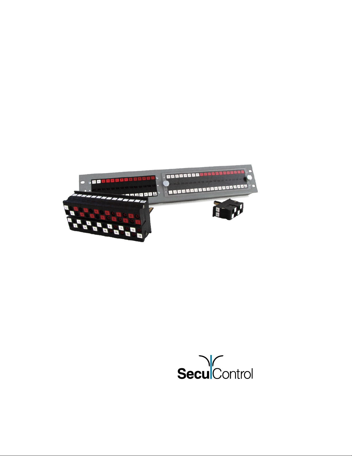
1 Introduction
The ITS / STP Test Block & Plug (4600 Series)
The ITS is a test block for interfacing substation devices (protection relays, fault
recorders, revenue meters, . . . ) to the voltage and current transformers and to other
equipment on the system side of a power grid.
STP is a test plug keyed to a particular configuration of ITS Test Blocks. Once inserted
into the corresponding test block, the STP Test Plug isolates the substation devices
from the system side equipment. Once the test plug is inserted the secondary injection
can be performed.
Key Features
•Finger-safe test block and test plug increase safety during testing
•Test plugs are keyed to the corresponding test blocks and help eliminate the
most common human errors during testing - and their sometimes costly conse-
quences
•Built-in automatic operating sequence prevents spurious breaker operation
•Extremely low internal resistance (<2 mΩ) helps reduce heat inside cabinets
and panels and decreases the risk of saturation when using 1 A current trans-
formers
•Available in 7, 10, 14 or 20 pole configurations
•Facilitates efficient, standardized testing procedures
Applicable Models
Information in this document applies to all 4600-series ITS Test Blocks and STP Test
Plugs manufactured after February 2012.
1

1. INTRODUCTION
Unpacking
Unpack the product carefully and make sure that all pertinent parts like mounting
screws (and dust covers, if included) are put aside so they will not be lost.
Check the contents against the packing list. If any of the contents listed are missing,
please contact SECUCONTROL immediately (see contact information at the rear cover
of this manual).
Examine the product for any shipping damage. If the product is damaged, notify
the shipping company without delay. Only the consignee (the person or company
receiving the unit) can file a claim against the carrier for shipping damage.
Part Number and Manufacturing Date Location
Part number and manufacturing date are stated on a label on the right side of the test
block or test plug.
Safety Symbols
The following symbols are located on different parts of the equipment and in this
manual:
Paragraphs marked with this symbol contain information which,
if not properly followed, may cause damage to the equipment
and/or installation.
Paragraphs marked with this symbol contain information which,
if not properly followed, may cause personal injury or even
death.
General Safety Instructions
Installation and operation of the products described in this manual is only to be per-
formed by personnel that has been trained or is knowledgeable in substation protec-
tion, automation and control.
This instruction manual is an integral part of the scope of delivery and provides basic
instructions for installation and operation of the equipment here described. Shall ad-
ditional information be needed, please contact SECUCONTROL at any of the addresses
provided on the rear cover of this document.
Do not disassemble the test block or test plug. Correct alignment of internal parts is
critical in order to provide insulation and arch-avoidance.
The warranty will be void if the test block or test plug is disassembled (or otherwise
handled inappropriately). SecuControl does not assume responsibility for any dam-
2

General Safety Instructions
ages arising out of mishandling of our products, including test blocks / test plugs that
have been disassembled by parties other than SecuControl.
3


2 Application
Schematic Symbols
Following symbols are suggested in order to represent the ITS Test Block in schematic
diagrams.
Symbol Description
S
V
Signal, Voltage (single pole)
- C
C - - C
- C -
- C -
C -
Current (2-pole, 4-pole)
5

2. APPLICATION
Typical Connection Schematic
3
2
1
N
V V VV
- CC - - CC - - CC -
1
1
2
2
3
3
4
4
5
5
6
6
7
7
8
8
9
9
10
10
ITS - 4610PTB04H
a-side
b-side
6
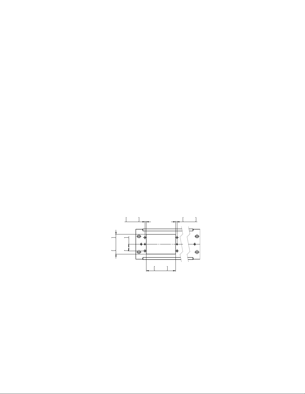
3 Installation
Panel Cutouts, Drilling Plans and Mounting
The cutout for the ITS Test Block must be done using the cutout plan for the correct
size ITS, shown below. The thickness of the panel sheet must not exceed 3 millimeters
(0.118 inches). The threaded holes M4 in the panel cutout diagram are only required
when using ITS dust covers which are an additional option.
Use the provided 4 pc. M4x10 button head screws with hexagon socket (2.5mm) to
fix the ITS Test Block in the panel cutout. The test block has to be inserted from the
back side and screwed from the front side.
7-pole Models
83mm
3,268in
56mm
2,205in
4mm
0,157in
4mm
0,157in
19mm
0,748in
7

3. INSTALLATION
10-pole Models
117.5mm
4.626in
56mm
2.205in
4mm
0.157in
4mm
0.157in
19mm
0.748in
14-pole Models
163,5mm
6,437in
56mm
2,205in
4mm
0,157in
4mm
0,157in
19mm
0,748in
20-pole Models
232,5mm
9,154in
56mm
2,205in
4mm
0,157in
4mm
0,157in
19mm
0,748in
8

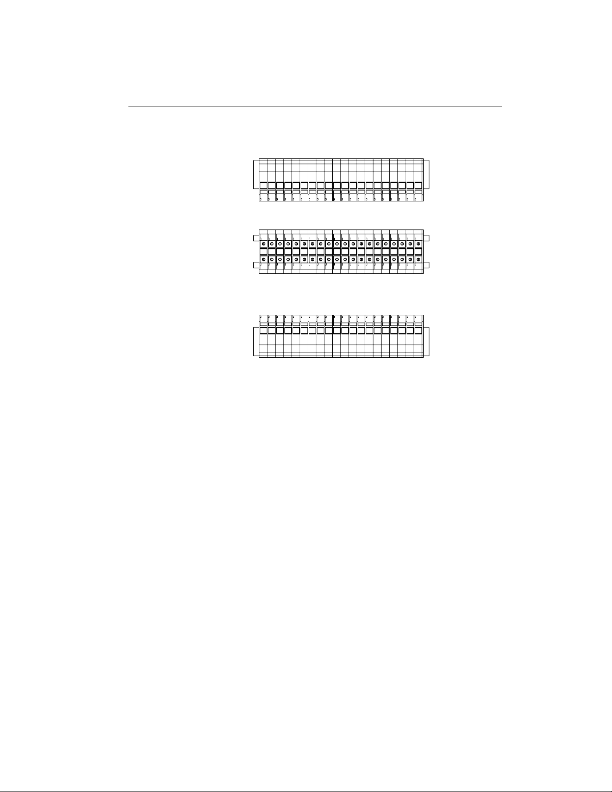
Wiring
Wiring
Electrical connection terminals are located on the top and bottom of the back side of
the ITS Test Block. The connection terminals accept ring cable lugs and spade cable
lugs. Use the included special phillips cross recessed pan head screws (UNC thread).
The screws are magnetic and can be mounted with power screwdrivers (fastening
torque 1.2 Nm).
Do not use metric or other improper screws or warranty will be void.
Recommended wire gauge is from 1,5 mm2(AWG 16) to 4 mm2(AWG 12).
CTs should be wired to the terminals provided for this purpose (in 2- or 4-pole com-
binations) to ensure automatic short circuiting upon insertion of STP Test Plugs or
individual test probes into the ITS Test Block. The terminals designated for the con-
nection of the CTs can be typically identified by the C- -C or C- -C- -C- -C
labeling1.
In addition to the two rows of labeling in the front, the ITS Test Block has one row of
labels each on the top, back and bottom side (when installed horizontally). All ”poles”
(or test block modules) are continuously numbered in the same way as it done on the
front of the test block (e.g. from 1 through 20 for a 20-pole test block). Pole number
1 (as seen from the front) is also numbered 1 when seen from the back side.
Each ”pole” (or test block module) hast two connection terminals that receive the
same number as the pole itself. One label on each the top side and the bottom side
of the test block (when installed horizontally) indicate with the letter ”a” or ”b” if the
terminals on that side are associated with the ”A-SIDE” (system side), or ”B-SIDE”
(device side).
1custom labeling may show other symbols or use other colors.
9

3. INSTALLATION
ITS functionality requires that the B-SIDE (device side) of the test block must be
connected with the device to be tested (e.g. protective relay), and the A-SIDE (system
side) must be connected to the electrical system (e.g. CTs, PTs and breakers).
Following figures represent the top, back and bottom side labeling of a typical ITS
Test Block.
7-pole Models
7 6 5 4 3 2 1
3 12456a
3 12456b
10

Wiring
10-pole Models
10 9 8 7 6 5 4 3 2 1
3 12456789 a
3 12456789 b
14-pole Models
14 13 12 11 10 9 8 7 6 5 4 3 2 1
3 1245678910111213 a
3 1245678910111213 b
11
3. INSTALLATION
20-pole Models
20 19 18 17 16 15 14 13 12 11 10 9 8 7 6 5 4 3 2 1
3 1245678910111213141516171819 b
3 1245678910111213141516171819 a
12

4 Operation
Handling of STP Test Plugs and test probes (smaller plugs for individual circuits)
should be done using only the handle and/or insulated plastic parts, since the fingers
may be connected to live equipment either via the test block or test equipment.
Store the STP Test Plugs and test probes carefully in order to avoid damage to the
metallic test fingers. SECUCONTROL recommends using one of the cases listed under
“Accessories” on page 19.
1. Remove the ITS dust cover (if one is used, optional accessory) by unscrewing
the two knurled screws that hold it, and lifting it up.
2. Carefully align the STP Test Plug or test probe with the corresponding positions
on the ITS Test Block.
3. Insert the STP Test Plug or test probe in one smooth and even movement into
the ITS Test Block.
Even insertion means that the test plug should always be positioned in a line
parallel to the test block while inserting - not at an angle.
There is no need to externally short-circuit the current transformers, since the
STP Test Plugs and test probes have internal shorting bars which will automat-
ically short circuit the corresponding circuits before opening them.
4. Connect cables from the test set with the corresponding STP Test Plug or test
probe.
For the purpose of injecting currents and voltages into the connected device (e.g.
relay), the test set must be connected to the B-SIDE (device side) of the STP
Test Plug or test probe. The connection of the test set to the test plug should be
made after the plug has been inserted into the ITS Test Block.
13

4. OPERATION
5. Once you are ready to resume normal operation, disconnect the cables from the
STP Test Plug or test probe.
6. Finally, remove the STP Test Plug or test probe in a single, even and continuous
movement.
7. Reattach the dust cover (if one is used).
14

5 Technical Specifications
Electrical
Current Withstand 30 A continuously
500 A for 1 second
Maximum voltage 600 V
Contact resistance ≤2mΩ
Dielectric Withstand 3.0 kV RMS for 1 minute between adjacent
contact pairs and between any contact pair and
other metal parts
2.0 kV RMS for 1 minute between open con-
tacts when test plug is inserted
Voltage Impulse 3 positive and 3 negative impulses of 5 kV
peak, 1.2/50 µs, 0.5 J between adjacent contact
pairs and between all contact pairs and other
metal parts
UL94 Flammability Class V-0
Enclosure Protection IP20 without cover
IP50 with optional dust cover attached
ITS / STP has been classified as electromagnetically benign by the Guide for the
EMC Directive 2004/108/EC and is, therefore, excluded from the scope of the EMC
Directive.
ITS / STP meet or exceed all requirements from ANSI / IEEE C37.90-2005.
15
5. TECHNICAL SPECIFICATIONS
Mechanical
# of poles 7 10 14 20
ITS Weight (kg) 0,49 0,67 0,91 1,26
(lbs) 1,08 1,48 2,01 2,78
STP Weight (kg) 0,33 0,46 0,65 0,93
(without Handle) (lbs) 0,73 1,01 1,43 2,05
STP Weight (kg) 0,54 0,69 0,90 1,21
(with Handle) (lbs) 1,19 1,52 1,98 2,67
STP Weight (kg) 0,57 0,73 0,94 1,25
(with fitting screws) (lbs) 1,26 1,61 2,07 2,76
The above table shows typical standard sizes. Please contact SECUCONTROL for
additional information regarding other pole lengths.
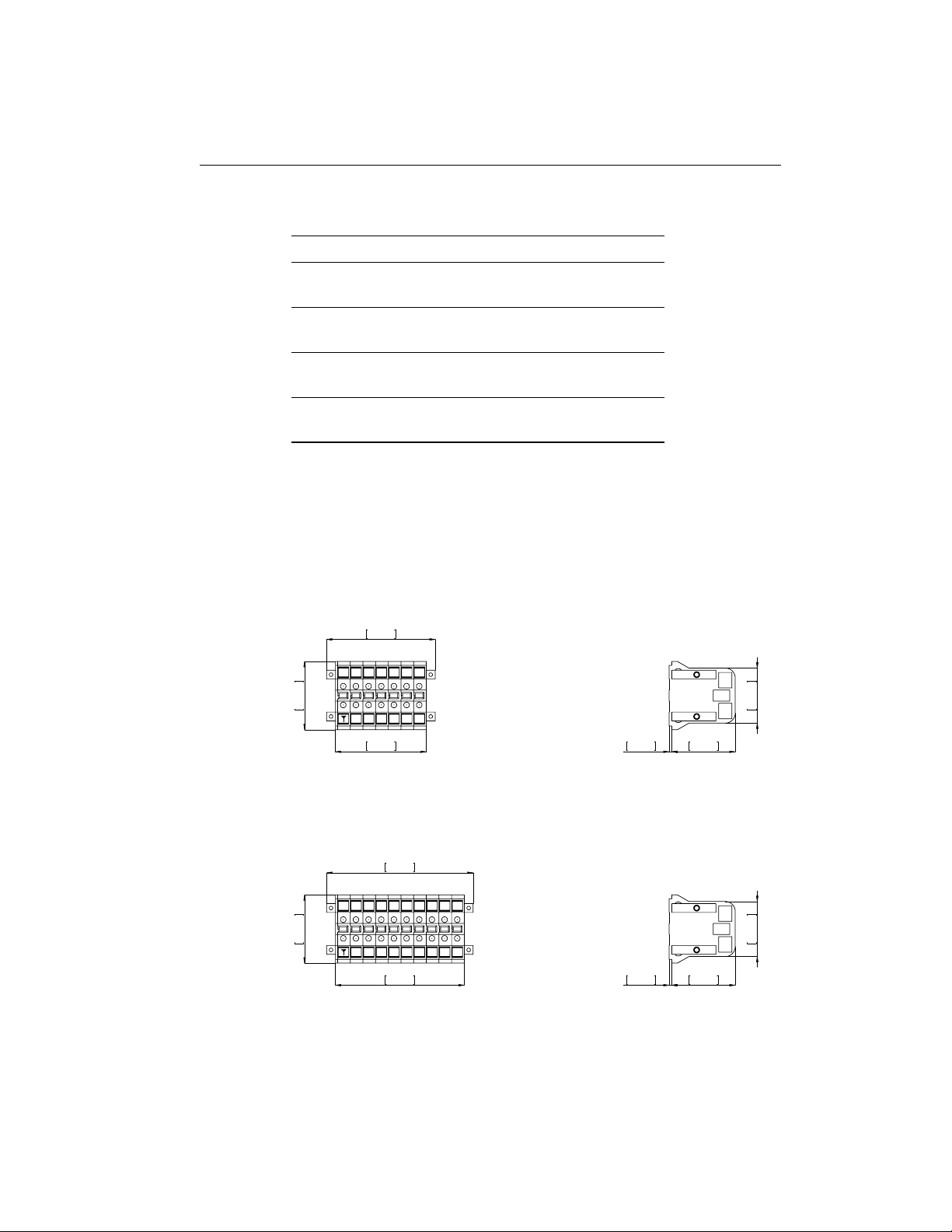
Dimensional Drawings
7-pole Models
82.5mm
3.248in
98.5mm
3.878in
62mm
2.441in
50mm
1.969in
57.5mm
2.264in
2.5mm
0.098in
2 3 4 5 6
ITS
Exp07
10-pole Models
117mm
4.606in
133mm
5.236in
62mm
2.441in
50mm
1.969in
57.5mm
2.264in
2.5mm
0.098in
2 3 4 5 6 7 8 9
ITS
Exp10
16
This manual suits for next models
1
Table of contents
Other SecuControl Test Equipment manuals


