Secure Care 135DE User manual

A01350693 Rev: P ECO: 7476 Date: 04/14/08
Secure Care Products®, Inc.
Installation Manual
135DE System
39 Chenell Drive
Concord, NH USA 03301-8501
Phone: (800) 451-7917 / (603)223-0745
Fax: (603) 227-0200
http://www.securecare.com
© 2004 Secure Care Products®, Inc.
CONTENT IS SUBJECT TO CHANGE WITHOUT NOTICE
Please contact your
Distributor /
Installer for service …
Tel.: ___________________________

A01350693 Rev:P ECO: 7476 Date: 04/14/08 2
Table of Contents
SECTION 1 IMPORTANT NOTICES 6
PLEASE READ THIS MANUAL BEFORE BEGINNING THE INSTALLATION OF A SECURE CARE SYSTEM 6
SECTION 2 SYSTEM BLOCK DIAGRAM 9
SECTION 3 POWER AND GROUNDING REQUIREMENTS 10
SECTION 4 TYPICAL SYSTEM INSTALLATION 12
SECTION 5 SPECIFICATIONS 13
Device Electrical Specifications 13
SECTION 6 SYSTEM COMPONENT DESCRIPTIONS 14
135DE Exit Panel 14
XIU 16
ID Nurse Station Console 17
203/204 LED Nurse Station Annunciator 18
Indoor/Outdoor Remote Keypad Layout 19
Indoor/Outdoor (N/O) Push Button Layout 19
SECTION 7 STANDARD FEATURES 20
Primary Reset (Escort) Code 20
Tertiary Reset (Escort) Code 20
Secondary Reset (Programming) Code 20
Selectable Delayed Egress Timing 20
Latching Delayed Egress 20
Software Verification 20
SECTION 8 THEORY OF OPERATION 21
SECTION 9 INSTALLATION AND CONNECTIONS 22
Basic Installation of Mounting Enclosures 22
Surface Mount Enclosure (XIU, 135DE) 22
Flush Mount Enclosure (XIU, 135DE) 23

A01350693 Rev:P ECO: 7476 Date: 04/14/08 3
Flush Mount Enclosure (ID Nurse Station Console, A02040901 LED Nurse Station Annunciator) 24
Surface Mount Enclosure (ID Nurse Station Console, A02040901 LED Nurse Station Annunciator) 25
Remote Annunciation 26
A02030901 (A02040901) Nurse Station Annunciator 26
Secure Care Software to XIU Connection 27
Interfacing Magnetic Locks 28
Interfacing the Magnetic Solutions Lock 29
Interfacing Two Magnetic Solutions Locks 30
Interfacing the Push Button and Remote Keypad 31
Delayed Egress and Fire Alarm Connections 32
135DE Exit Panel to External Receiver Connections 33
Second External Receiver Connections 34
SECTION 10 PROGRAMMING 35
Reset (Escort) Codes 35
Primary Code 35
Secondary Code 35
Secondary Code Reset 35
Tertiary Code 35
Escort Time 35
Delayed Egress Release Time 36
Delayed Egress Activation Time 36
Latching Delayed Egress 37
One Second Irreversible Latching Delayed Egress 37
Fire Alarm Input Selection 38
Latching Fire Alarm 38
Life Safety Lock 38
Panel ID Code 38
PM Mode Feature 39
Software Version 39
Elevator Mode 39
Loiter Alarm 40
Advanced Security Mode 40

A01350693 Rev:P ECO: 7476 Date: 04/14/08 4
Antenna Selection 41
Antenna Range Adjustment 41
SECTION 11 TESTING 42
Recommended Weekly Testing 42
Testing Wandering Patient Monitoring with Lock 42
Delayed Egress Feature Test 42
Recommended Monthly Testing 42
Fire Alarm Release Feature Test 42
Recommended Annual Service 42
Battery Replacement 42
Using a Transmitter/System Tester 43
Testing a Transmitter Using the 135 Tester: 43
Testing a Door System Using the 135 Tester: 43
SECTION 12 TROUBLESHOOTING 44
SECTION 13 GENERAL PRODUCT WARRANTY STATEMENT 48
1. Notices 48
2. Limited Warranty 50
3. Limitations of Liability 51
4. Governing Law and Arbitration 51
5. Severability 52
6. Waiver 52
SECTION 14 COMPLIANCE INFORMATION 53
APPENDIX A UL LISTING REQUIREMENTS 55
APPENDIX B 230 VAC INPUT POWER SUPPLY CONNECTION 56
APPENDIX C FERRITE PLACEMENT 57
Recommended Ferrite Placement 57
Correct and Incorrect Ferrite Installation 58
APPENDIX D 983 EXTERNAL RECEIVER KIT 59

A01350693 Rev:P ECO: 7476 Date: 04/14/08 5
Table of Figures
FIGURE 2-1 SYSTEM BLOCK DIAGRAM 9
FIGURE 3-1 POWER SUPPLY TO EXIT CONNECTION 11
FIGURE 6-1 FRONT VIEW OF 135DE EXIT PANEL 14
FIGURE 6-2 REAR VIEW OF 135DE EXIT PANEL 15
FIGURE 6-3 REAR VIEW OF XIU 16
FIGURE 6-4 REAR VIEW OF ID NURSE STATION CONSOLE 17
FIGURE 6-5 NEW A02030901 NURSE STATION ANNUNCIATOR 18
FIGURE 6-6 NEW A02040901 NURSE STATION ANNUNCIATOR 18
FIGURE 6-7 REAR VIEW OF REMOTE KEYPAD 19
FIGURE 6-8 REAR VIEW OF PUSH BUTTON 19
FIGURE 9-1 SURFACE MOUNT ENCLOSURE FOR EXIT PANELS 22
FIGURE 9-2 FLUSH MOUNT ENCLOSURE FOR EXIT PANELS 23
FIGURE 9-3 FLUSH MOUNT ENCLOSURE FOR NURSE STATIONS 24
FIGURE 9-4 SURFACE MOUNT ENCLOSURE FOR NURSE STATIONS 25
FIGURE 9-5 CONNECTION BETWEEN THE A02030901/A02040901 AND THE 135DE EXIT PANEL 26
FIGURE 9-6 XIU TO COMPUTER CONNECTION 27
FIGURE 9-7 135DE EXIT PANEL TO DORTRONICS LOCK CONNECTIONS 28
FIGURE 9-8 135DE EXIT PANEL TO MAGNETIC SOLUTIONS LOCK CONNECTIONS 29
FIGURE 9-9 135DE EXIT PANEL TO TWO MAGNETIC SOLUTIONS LOCKS CONNECTIONS 30
FIGURE 9-10 PUSH BUTTON AND REMOTE KEYPAD TO 135DE EXIT PANEL CONNECTION 31
FIGURE 9-11 DELAYED EGRESS AND FIRE ALARM CONNECTIONS 32
FIGURE 9-12 EXIT PANEL TO EXTERNAL RECEIVER CONNECTION 33
FIGURE 9-13 CONNECTING TWO EXTERNAL RECEIVERS 34

A01350693 Rev:P ECO: 7476 Date: 04/14/08 6
PLEASE READ THIS MANUAL BEFORE BEGINNING
THE INSTALLATION OF A SECURE CARE SYSTEM
This installation manual is provided for reference by purchasers and installers of Secure Care Products, Inc.’s
(“Secure Care’s”) systems. This manual is not intended as a catalog of warnings for the protection of anyone or as a
substitute for obtaining professional training or assistance in the design of a facility’s security procedures and systems, or in
the installation, set-up, testing, support, operation, maintenance, repair or use of Secure Care’s systems. Nothing in this
manual modifies the terms of Secure Care’s General Product Warranty Statement or of any written agreement signed by
Secure Care or creates further warranties or extends benefits of any sort to anyone beyond those already expressly established
in Secure Care’s General Product Warranty Statement and in any written contract signed by Secure Care.
1. Secure Care is Not Responsible for the Locks
ALL LOCKS USED WITH SECURE CARE’S SYSTEM ARE DESIGNED, MANUFACTURED, LABELED AND
DELIVERED SOLELY BY AN INDEPENDENT VENDOR OVER WHOM SECURE CARE HAS NO CONTROL
AND FOR WHOSE ACTIONS OR FAILURES TO ACT SECURE CARE DISCLAIMS ALL RESPONSIBILITY.
REGARDLESS OF WHETHER THE LOCKS CARRY SECURE CARE’S LOGO OR NAME OR ANY OTHER
TRADEMARK, SERVICE MARK OR TRADE NAME USED OR CLAIMED BY SECURE CARE, SECURE
CARE DISCLAIMS ALL WARRANTIES, EXPRESS OR IMPLIED, WITH RESPECT TO THE LOCKS AND/OR
THEIR USE WITH OR OPERATION IN THE SECURE CARE SYSTEM, INCLUDING, WITHOUT
LIMITATION, ALL IMPLIED WARRANTIES OF MERCHANTABILITY, FITNESS FOR A PARTICULAR
PURPOSE, TITLE AND/OR NON-INFRINGEMENT. SECURE CARE ALSO DISCLAIMS ALL OBLIGATIONS
WITH RESPECT TO THE LOCKS AND/OR THEIR USE WITH OR OPERATION IN THE SECURE CARE
SYSTEM THAT MIGHT OTHERWISE ARISE OR BE IMPLIED FROM THE FACT THAT SUCH LOCKS
CARRY SECURE CARE’S LOGO OR NAME OR ANY OTHER TRADEMARK, SERVICE MARK OR TRADE
NAME USED OR CLAIMED BY SECURE CARE OR FROM THE DELIVERY OR INSTALLATION OF THE
LOCKS WITH SECURE CARE SOFTWARE, PARTS AND/OR PRODUCTS OR FROM A COURSE OF
DEALING OR USAGE IN TRADE. ALL RESPONSIBILITY FOR DESIGNING, MANUFACTURING,
LABELING AND WARNING OF HIDDEN DEFECTS OR DANGERS IN THE LOCKS AND/OR THEIR USE
WITH AND OPERATION IN THE SECURE CARE SYSTEM RESTS EXCLUSIVELY WITH THE
INDEPENDENT VENDOR, AND ANY CLAIMS, COSTS, DAMAGES OR LIABILITIES ARISING FROM THE
LOCKS AND/OR THEIR USE WITH OR OPERATION IN THE SECURE CARE SYSTEM SHALL BE MADE
SOLELY AGAINST THE INDEPENDENT VENDOR.
2. Secure Care Is Not Responsible for The Computer Hardware.
IF YOU PURCHASE COMPUTER HARDWARE THROUGH SECURE CARE AND REQUEST THAT SECURE
CARE SOFTWARE BE INSTALLED AND TESTED ON THAT HARDWARE AT THE FACTORY, SECURE
CARE WARRANTS ONLY THAT THE HARDWARE AND THE SOFTWARE PACKAGES WERE INSTALLED,
SET-UP AND TESTED PRIOR TO SHIPMENT IN ACCORDANCE WITH ALL SECURE CARE PRODUCT
MANUALS AND THAT, AT THE TIME THE HARDWARE AND THE SOFTWARE PACKAGES WERE
FINALLY INSPECTED AT THE FACTORY, THEY WERE PERFORMING (SUBJECT TO SECURE CARE’S
SPECIFIED TOLERANCES) IN ACCORDANCE WITH SECURE CARE’S SPECIFICATIONS. SECURE CARE
WILL NOT BE RESPONSIBLE FOR ANY DEFECTS IN OR PROBLEMS CAUSED BY THE HARDWARE, ALL
CLAIMS FOR WHICH MUST BE MADE TO THE HARDWARE MANUFACTURER AND/OR VENDOR.
SECURE CARE DISCLAIMS ALL WARRANTIES, EXPRESS OR IMPLIED, WITH RESPECT TO THE
HARDWARE AND/OR ITS USE WITH OR OPERATION IN THE SECURE CARE SYSTEM, INCLUDING,
WITHOUT LIMITATION, ALL IMPLIED WARRANTIES OF MERCHANTABILITY, FITNESS FOR A
PARTICULAR PURPOSE, TITLE AND/OR NON-INFRINGEMENT. SECURE CARE ALSO DISCLAIMS ALL
OBLIGATIONS WITH RESPECT TO THE HARDWARE AND/OR ITS USE WITH OR OPERATION IN THE
SECURE CARE SYSTEM THAT MIGHT OTHERWISE ARISE OR BE IMPLIED FROM THE FACT THAT
SUCH HARDWARE CARRIES SECURE CARE’S LOGO OR NAME OR ANY OTHER TRADEMARK,
SERVICE MARK OR TRADE NAME USED OR CLAIMED BY SECURE CARE OR FROM THE DELIVERY
OR INSTALLATION OF THE HARDWARE WITH SECURE CARE SOFTWARE, PARTS AND/OR
PRODUCTS OR FROM A COURSE OF DEALING OR USAGE IN TRADE. ALL RESPONSIBILITY FOR
DESIGNING, MANUFACTURING, LABELING AND WARNING OF HIDDEN DEFECTS OR DANGERS IN
SECTION 1 IMPORTANT NOTICES

A01350693 Rev:P ECO: 7476 Date: 04/14/08 7
THE HARDWARE AND/OR ITS USE WITH AND OPERATION IN THE SECURE CARE SYSTEM RESTS
EXCLUSIVELY WITH THE HARDWARE MANUFACTURER AND/OR VENDOR, AND ANY CLAIMS,
COSTS, DAMAGES OR LIABILITIES ARISING FROM THE HARDWARE AND/OR ITS USE WITH OR
OPERATION IN THE SECURE CARE SYSTEM SHALL BE MADE SOLELY AGAINST THE HARDWARE
MANUFACTURER AND/OR VENDOR.
3. Several Factors Outside the Secure Care System Can Affect its Performance
Secure Care’s software, parts and products are designed for operation in a wireless system. However, the range,
performance, and predictability of any wireless system, including Secure Care’s, is dependent on several factors,
including, but not limited to, the following: building structure; environmental extremes (e.g., temperature, earth
tremors, air pollution, etc.); the proximity of other wireless devices; the presence of variable speed products; sources
of Radio Frequency Interference (RFI); physical orientation and positioning of the equipment; and sources of
Electro Static Discharge (ESD). Secure Care is not responsible for the effect of these types of factors on operation
of its software, parts and products and disclaims all responsibility for any claim relative thereto.
4. The Secure Care System Must be Properly Installed
Secure Care's system must be installed, set-up, tested, supported, operated, maintained, repaired and used only in
accordance with all manuals and instructions (including the user, installation, technical and other manuals) issued
by Secure Care (the "Product Manuals"). It is your responsibility to assure that any person who might be installing,
setting-up, testing, supporting, maintaining or repairing the Secure Care system knows the contents of and has
access to the Product Manuals and has successfully completed Secure Care technical training. It is also your
responsibility to assure that any person who might be operating or using this Product knows the contents of and
has access to the Product Manuals and has successfully completed Secure Care in-service training. Secure Care can
not be responsible for performance problems caused by a failure to follow prescribed and appropriate procedures
for installation, set-up, testing, support, operation, maintenance, repair and use.
All adjustable features on new and repaired Secure Care software, parts and products are shipped with “factory
default” settings. These “factory default” settings may not comply with building and life safety codes or other
applicable laws and regulations in the location where they are installed or operated. Secure Care strongly
recommends, therefore, that the settings on all Secure Care software, parts and products be checked and, if
necessary, reset to comply with local building and life safety codes and other applicable laws and regulations at the
time of any installation, set-up, testing, support, maintenance or repair.
5. Performance of the Secure Care System Software Depends on Proper Maintenance
Secure Care’s system is driven by software. However, the performance and reliability of any software-driven system
depends on adequately maintaining the recommended minimum configuration of computing platform, operating
systems and applications programs and on regularly performing industry-standard and application-specific backup
processes. If recommended minimum configurations of computing platform, operating systems, and applications
programs are not adequately maintained, or if appropriate backups are not regularly performed, the software may
not drive the system as intended. Secure Care is not responsible for operational problems caused by a failure to
perform these maintenance and backup procedures and disclaims all responsibility for any claim relative
thereto.
6. Only a Qualified Service Technician Should Work on a Secure Care System
Secure Care does not authorize, and strongly recommends against, any installation or field replacement of software,
parts or products by untrained contractors or facility staff. Such work can be hazardous, can render the system
ineffective and will void any Secure Care warranty or liability that might otherwise relate to the system.
Before any software, parts or products which have been designed and manufactured by Secure Care can be safely
installed, set-up, tested, supported, maintained or repaired, technical training in accordance with standards
established by Secure Care is required. Regardless of how Secure Care’s software, parts or products are obtained,
they should not be installed, set-up, tested, supported, maintained or repaired by any person who has not
satisfactorily completed that technical training (a “qualified service technician”.) When Secure Care’s software,
parts or products are sold separately from installation services, it is assumed that only a qualified service technician

A01350693 Rev:P ECO: 7476 Date: 04/14/08 8
will conduct any installation, set-up, testing, support, maintenance or repair involving that software, part or
products.
7. Any Work Must Comply with Electrical and Life Safety Codes
It is important that any installation, set-up, testing, support, operation, maintenance, repair or use involving the
system comply with all local and national electrical and life safety codes. If you have any questions about
compliance with those codes, please contact your local authorities.
8. Immediately Have Replacements or Repairs Checked On-Site by a Qualified Service Technician
Secure Care receives and responds to telephone and dial-in inquires (the “Help Line”) about its software, parts and
products for the purpose of discussing users’ experiences with Secure Care’s system, helping users better understand
how their systems work, and providing ideas about what may be causing difficulties. However, Secure Care cannot
accurately diagnose the cause of any problems or give complete instructions on how to fix problems over the
telephone or Internet. The only way to assure that software, parts or products are installed, set-up, tested,
supported, maintained or repaired correctly or that a Secure Care system is functioning properly is to have it
examined on site by a qualified service technician. In addition, Secure Care software, parts and products cannot be
operated or used correctly by anyone who has not successfully completed Secure Care in-service training. Secure
Care’s Help Line is not a substitute for on-site diagnosis and servicing by a qualified service technician or for
successful completion of Secure Care in-service training. Secure Care strongly recommends that any installation,
set-up, testing, support, maintenance or repair of a system that is performed by a person who has not satisfactorily
completed technical training in accordance with standards established by Secure Care be immediately checked on-
site by a qualified service technician.
WARNING: EVEN SLIGHT MODIFICATIONS TO THE SYSTEM OR CHANGES IN THE OPERATING
ENVIRONMENT MAY CAUSE SECURE CARE’S SYSTEM TO MALFUNCTION. THE ONLY WAY TO
ASSURE THAT SECURE CARE’S SYSTEM HAS BEEN INSTALLED, SET-UP, TESTED, SUPPORTED,
MAINTAINED AND REPAIRED CORRECTLY IS TO HAVE A QUALIFIED SERVICE TECHNICIAN DO THE
WORK.
9. The Secure Care System is not a Substitute for Careful Identification and Monitoring by
Professional Staff
Secure Care’s software, parts and products have been designed to augment a facility’s reasonable procedures for
protecting residents, patients, and infants. However, no system or combination of procedures and equipment can
eliminate all risk or assure complete security. Secure Care’s system is not intended as a substitute for the careful
identification and monitoring of residents, patients, and infants by a facility’s professional staff.
Revised 11/16/07

A01350693 Rev:P ECO: 7476 Date: 04/14/08 9
SECTION 2 SYSTEM BLOCK DIAGRAM
PERSONAL
COMPUTER
WITH
SECURE CARE
SOFTWARE
XIU
135 135 500DE
MAGNETIC LOCK
ELEVATOR
CONTROL
(135 and 135DE
only)
FIRE ALARM
CONTROL
Connection
required for any
device with
magnetic door lock.
EXTERNAL
ANTENNA
(135 and 135DE only)
EXTERNAL
KEYPAD
NURSE
STATION
PUSH
BUTTON
135DE
POWER
SUPPLY
POWER
SUPPLY
POWER
SUPPLY
POWER
SUPPLY
or
RS232 one way to Nurse Station or
Secure Care Software
Earth ground
connection at J1
position "F"
POWER
SUPPLY
Bi-directional CAN (Controller Area Network) communications bus. Maximum 94 devices connected to XIU.
MAGNETIC LOCK
FIRE ALARM
CONTROL
Connection
required for any
device with
magnetic door lock.
SUPPLY
POWER
A01350691, Rev. A
Fig. 2
Figure 2-1 System Block Diagram
NOTE: This diagram is UL required. Do not remove or change Part Number or Figure #.

A01350693 Rev:P ECO: 7476 Date: 04/14/08 10
Each Exit Panel will require a 110/220/230VAC duplex outlet specific to regional or country options (minimum 2 Amp) within ten
cable feet of the intended installation location. The use of emergency power circuits is highly recommended due to possible facility
power failures.
NOTES:
•Power Wire: 14/2 stranded, unshielded (SCP Part # C60008473). Power wire is a UL requirement. Failure to
use this wire removes the UL listing.
•Power Supply: SCP Part # C40006008. For overseas 230VA Power Supply refer to Appendix B.
•Do not connect to a receptacle controlled by a switch.
•Do not extend the power supply cord provided. The maximum distance the duplex outlet should be from
the Exit Panel is ten cable feet.
SECTION 3 POWER AND GROUNDING REQUIREMENTS
A01350693 Rev:P ECO: 7476 Date: 04/14/08 11
FIR
EPUS
HDOO
REGRES
S
LOCK AUX
SECURECARE
PRODUCTS
AUXLOCK
-
+
NO C
NC NO C
NC NO C
NC NO C
NC - +
KEYPAD
ON
1 2 3 4
1 2 3 4 5 6
7
1 2 3
4CANL CANH GND
FIR
EPUS
HDOO
REGRES
S
LOCK AUX
SECURECARE
PRODUCTS
AUXLOCK
-
+
NO C
NC NO C
NC NO C
NC NO C
NC - +
KEYPAD
ON
1 2 3 4
1 2 3 4 5 6
7
1 2 3
4CANL CANH GND
FIR
EPUS
HDOO
REGRES
S
LOCK AUX
SECURECARE
PRODUCTS
AUXLOCK
-
+
NO C
NC NO C
NC NO C
NC NO C
NC - +
KEYPAD
ON
1 2 3 4
1 2 3 4 5 6
7
1 2 3
4CANL CANH GND
FIR
EPUS
HDOO
REGRES
S
LOCK AUX
SECURECARE
PRODUCTS
AUXLOCK
-
+
NO C
NC NO C
NC NO C
NC NO C
NC - +
KEYPAD
ON
1 2 3 4
1 2 3 4 5 6
7
1 2 3
4CANL CANH GND
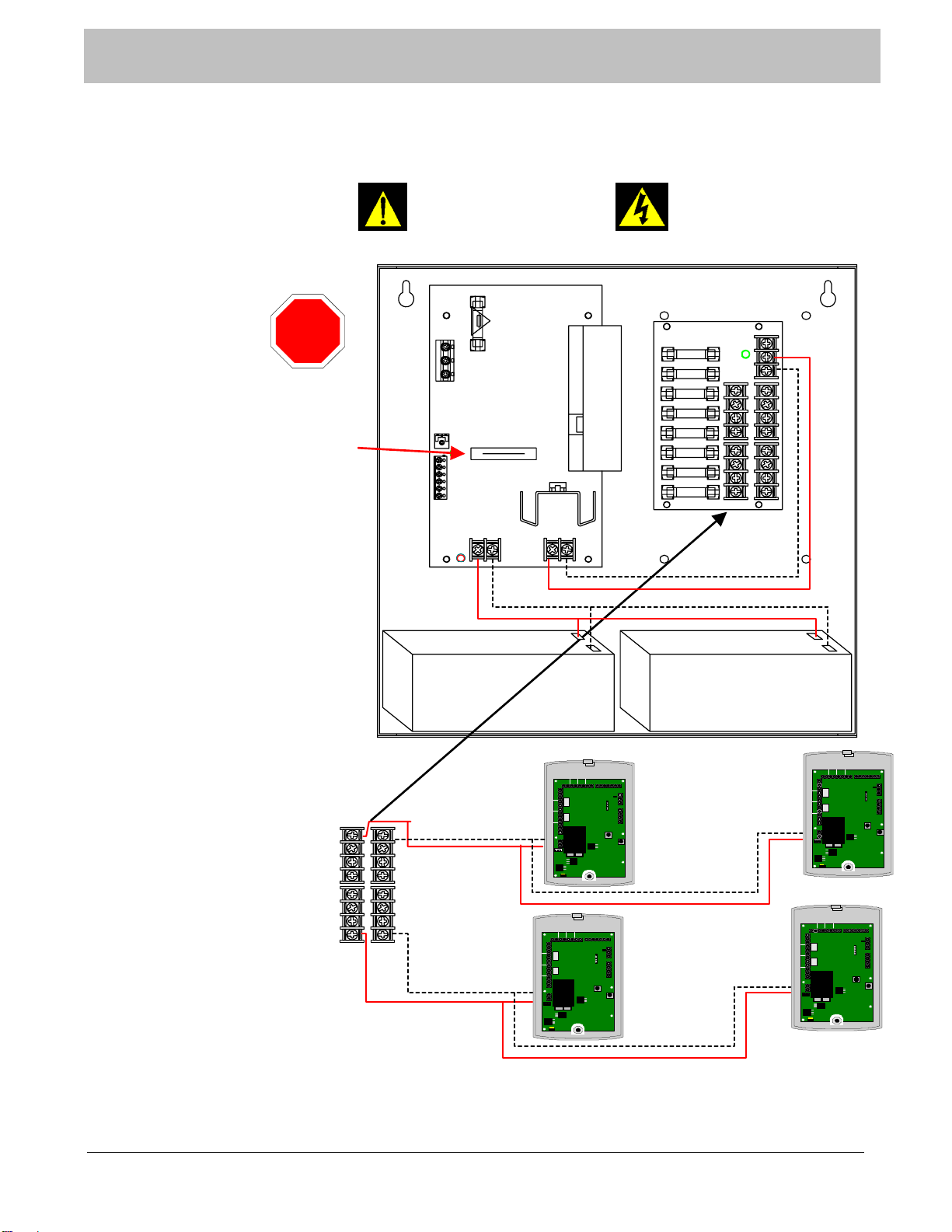
COMMON POWER OUTPUTS
FUSED POWER OUTPUTS
N
P
+
-
+
+
+
-
-
-
Max 8 Per
output
Max 8 Per
output
Maximum 32
exits per
power supply
(6 Amp)
NOTE:
Refer to
manufacturer’s
documentation when
installing the power
supply
12VDC
12VDC
COMMON POWER OUTPUTS
FUSED POWER OUTPUTS
N
PPD8
N P S
MAIN FUSE
L G N
3.5A 250V
AL600ULXB
AC
+BAT-
DC
+ DC -
BAT FAIL NC C NO NC C NO
AC FAIL
FNAME
24VDC OPEN
12VDC CLOSED
Verify Switch Is Set
For 12VDC Before
Applying Power To
Power Supply
STOP
115VAC
Power
Mains
Non-Power
Limited
+--
+
Battery 1 Battery 2
•
Risk of shock
•
Dry location use only
•
For indoor use only
NOTE
: Refer to
Appendix D for
OverSeas 230VA
Power Supply
Figure 3-1 Power Supply to Exit Connection
SECTION 3 POWER AND GROUNDING REQUIREMENTS

A01350693 Rev:P ECO: 7476 Date: 04/14/08 12
As with any Wandering Monitoring System, each application can be different. Use the guidelines below as a basic understanding of
what a standard application would be like.
•Identify all the equipment that is to be installed. Inspect for any damage that may have resulted during shipment. If
damage is found, notify the shipping carrier immediately and arrange for an inspection. Be sure to retain all shipping
and packing materials.
•Install all communication wires from each exit system to the remote system annunciator location.
•Determine the location of the Exit Control Panel, making sure to accommodate for any local, state, or federal codes
or guidelines including ADA requirements, and mount as required. Standard applications would place this
equipment on the wall at the center of the door height on the latch side.
•Mount the Electromagnetic Lock in strict accordance with the manufacturer installation instructions. Be sure to
comply with all Life Safety and Electrical Codes as required.
•Mount the Magnetic Door Contacts provided with the Exit Kit on the latch side of the door. These contacts provide
a method of monitoring the open or closed status of the door.
•Route all necessary peripheral connection wires into the Exit Control Panel mounting box. These would include wires
such as communication, magnetic contacts, exit power, magnetic lock power, etc.
•Prepare all wires and make connections to the exit system. Special care should be taken to prevent loose connections
and shorts.
•Proceed to the remote system annunciator location to mount as required. This device should be easily visible by staff
for monitoring of the system. Common locations are centralized nurse stations or staffed reception areas.
•Make all necessary wiring connections as shown on the following pages.
•Plug in all power supplies and batteries. The system is now ready for testing.
SECTION 4 TYPICAL SYSTEM INSTALLATION

A01350693 Rev:P ECO: 7476 Date: 04/14/08 13
Device Electrical Specifications
XIU, 500DE, 135, 135DE & ID Exit Panels
•Input Power: 12VDC/1A
•Relay Specifications: Max. 30VDC (only) 1 Amp
•Battery Back Up: Rechargeable 9VDC Ni-MH battery
•Battery Back Up Time: Approximately 30 minutes
Nurse Station SCP P/N A02280903
•Input Power: 12VDC/500mA
•Battery Back Up: Rechargeable 9VDC Ni-MH battery
•Battery Back Up Time: Approximately 30 minutes
Magnetic Lock
•Input Power: 12VDC/1A
•Battery Back Up: None
UL Product Listings
•UL 294
•UL 1069
SECTION 5 SPECIFICATIONS

A01350693 Rev:P ECO: 7476 Date: 04/14/08 14
135DE
®
1 2 3
4 5 6
7 8 9
0
#
*
Secure Care Products, Inc.
Panel Information
135DE Exit Panel
Door is Alarming
( Flashing Red )
Door is armed ( Red )
LED will turn off when
Escort Code is entered.
Flashing Red Fire is
activated.
Transmitter
is within
range of
panel (Red)
When two transmitters
are present, center LED
is solid. When three or
more transmitters are
present, center LED
will blink. Keypad Punch
Indicator center LED
lights when any key is
pressed.
Panel is On
( Green )
Transmitter is
being
detected
(Flashing
Yellow)
135DE Exit Panel
NOTE: Not all exit panels will have every feature set or all components populated. Refer to specific part
number or exit panel model name for available feature sets.
Figure 6-1 Front View of 135DE Exit Panel
SECTION 6 SYSTEM COMPONENT DESCRIPTIONS
A01350693 Rev:P ECO: 7476 Date: 04/14/08 15
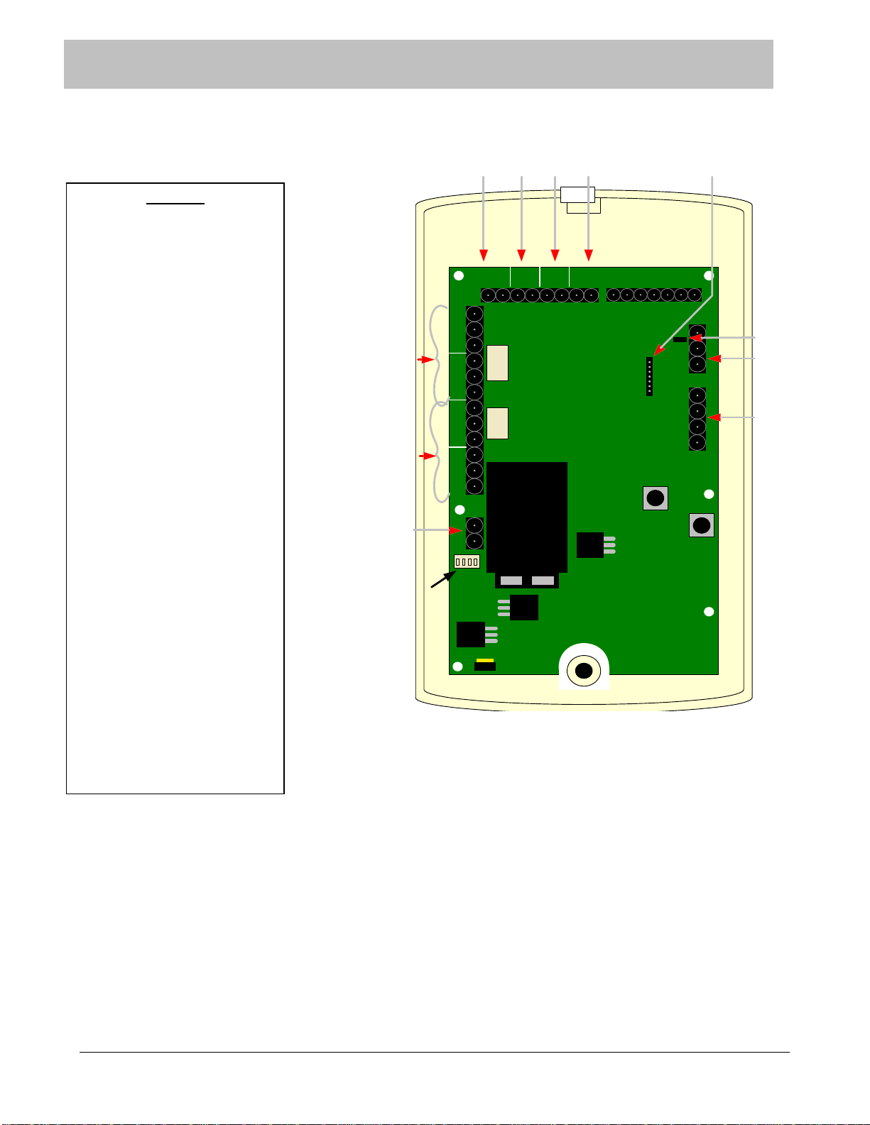
Figure 6-2 Rear View of 135DE Exit Panel
SECTION 6 SYSTEM COMPONENT DESCRIPTIONS
LEGEND
1. Electromagnetic lock Delayed
Egress connection
2. Normally Closed door contact
connection
3. Momentary Push Button or
Non-latching Key Switch
4. Fire alarm Normally Open dry
alarm relay connection (field
selectable)
5. Controlled area network (CAN)
connection
6. Remote Internal/External
Keypad connection (seven pin)
7. Electromagnetic lock relays ,
one and two connections
8. Auxiliary relays (one and two
connections)
9. DC power input connections.
10. CAN Bus termination jumper
11. External Model 135Receiver
connection. See Appendix D at
the end of this manual.
12. Dipswitches Power/Volume
FIRE PUSH DOOR EGRESS
LOCK AUX
CAN
L
CANHGND
SECURE CARE PRODUCTS
AUXLOCK
- +
NO C NC NO C NC NO C NC NO C NC - +
KEYPAD
O N
1 2 3 4
1 2 3 4 5 6 7
1 2 3 4
23416
7
8
9
5
12
10
1- Power
2- Mute
3-Loud/Soft
4- Not Used
11
A01350693 Rev:P ECO: 7476 Date: 04/14/08 16
XIU
FIRE PUSH DOOR EGRESS
AUX
CA
NL
CANHGND
SECURE CARE
PRODUCTS
LOCK
- +
NO C NC
- +
KEYPAD
O
N
1 2 3 4
1 2 3 4 5 6 7
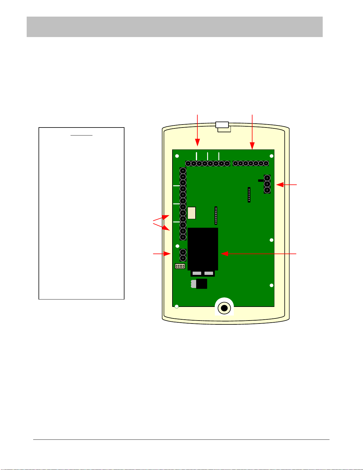
1) POWER
2) NOT USED
3) NOT USED
4) NOT USED
LOCK
NO C NC AUX
NO C NC NO C NC
2
4
5
6
3
1
Figure 6-3 Rear View of XIU
SECTION 6 SYSTEM COMPONENT DESCRIPTIONS
LEGEND
1. XIU to XIU (Only used
with Cutband System. Refer to
ID with Stat Manual)
2. RS-232 connection to
Nurse Station or SCP Software
3. Controlled area network
(CAN)
4. Back up battery holder
5. DC power input connection
6. Auxiliary relay connection
(Form C Relays that activate
during a cutband alarm)

A01350693 Rev:P ECO: 7476 Date: 04/14/08 17
ID Nurse Station Console
y
y
y
123
4
5
6
7
8
9
10
11 12
1. POWER
2.MUTE
3.LOUD/SOFT
4.N/A
Figure 6-4 Rear View of ID Nurse Station Console
SECTION 6 SYSTEM COMPONENT DESCRIPTIONS
LEGEND
1. Non-volatile RAM storage
2. RS-232output chip
3. RS-232 output connector
4. Software EPROM
5. RS-232 device input
connections ( Term. 9-16)
6. RS-232 input chip (Term.
13-16)
7. RS-232 input chip (Term. 9-
12)
8. Dry contact device input
(Term. 1-8)
9. DC input power connector
10. DC power regulator and
heat sink
11. Power / Volume control
switches
12. Back up battery holder

A01350693 Rev:P ECO: 7476 Date: 04/14/08 18
203/204 LED Nurse Station Annunciator
NOTE: Actual Nurse Station connections may differ from figures below.
Figure 6-5 New A02030901 Nurse Station Annunciator
Figure 6-6 New A02040901 Nurse Station Annunciator
SECTION 6 SYSTEM COMPONENT DESCRIPTIONS
LEGEND
1. Form C output relay
2. DC power inputs
3. Dry contact position inputs
(1-4)
4. Volume adjustment
5. Dry contact position inputs
(5-8)
6. DC power inputs
7. Shield drain ground
connection
8. Volume adjustment
LEGEND
1. Form C output relay
2. DC power input
3. Dry contact position inputs
(1-4)
4. Volume adjustment
+4321
-
All Terminal strips are
removable for ease of
installation
4
2 3
M L H
1
NO C NC
+4321
-
All Terminal strips are
removable for ease of
installation
M L H
NO C NC
+4321
-
All Terminal strips are
removable for ease of
installation
M L H
NO C NC
1 2 3
4
5
67
8

A01350693 Rev:P ECO: 7476 Date: 04/14/08 19
Indoor/Outdoor Remote Keypad Layout
Figure 6-7 Rear View of Remote Keypad
Indoor/Outdoor (N/O) Push Button Layout
Figure 6-8 Rear View of Push Button
SECTION 6 SYSTEM COMPONENT DESCRIPTIONS
1
2
3
LEGEND
1. Mounting screw holes
2. Seven pin connector for seven
conductor ribbon cable
3. Steel faceplate
LEGEND
1. Mounting screw holes
2. Spade lug terminal
connectors (Normally Open –
Activated Closed)
3. Steel Faceplate
1
2
3

A01350693 Rev:P ECO: 7476 Date: 04/14/08 20
SECTION 7 STANDARD FEATURES
The selective monitoring system is designed to augment your policy regarding security of infants, small children, or residents. If used
and tested properly, the system will provide many years of trouble free operation. The standard system consists of an Exit Panel, the
electromagnetic lock, the Receiver/Antenna, magnetic door contacts, and an active Transmitter.
The standard mode of operation for the Exit System allows free access of the door by nurse staff members and visitors but quietly
locks the door when a transmitter approaches the door. When the transmitter leaves the monitored area, the door unlocks and access
is again available for the nurse staff and visitors. If a nurse staff member is required to escort a transmitter out of the protected area,
an escort code can be entered into the Exit Panel keypad to allow both the nurse staff member and the transmitter to pass through
the perimeter without creating an alarm.
Other key features are described below and can be activated at the time of installation or at any time afterward by a trained
technician.
Primary Reset (Escort) Code – This code is used to reset an alarm condition or escort a monitored transmitter through a door
without creating an alarm condition. In the Advanced Security Mode, the primary reset (escort) code will not allow access through a
monitored door location. This code should not be given to family members or visitors. Only nurse staff members should be
allowed to reset an alarm condition or escort a transmitter out of the building without creating an alarm.
Tertiary Reset (Escort) Code - This code is used to reset an alarm condition or escort a monitored transmitter through a door
without creating an alarm condition. In the Advanced Security Mode, the tertiary reset (escort) code will not allow access through a
monitored door location. This code should not be given to family members or visitors. Only nurse staff members should be
allowed to reset an alarm condition or escort a transmitter out of the building without creating an alarm.
Secondary Reset (Programming) Code –In the Advanced Security Mode, the secondary code is used to escort a transmitter through
a monitored door. This code is also used to enter the programming mode of the system. This code should only be given to
authorized nursing staff members.
Selectable Delayed Egress Timing – This feature allows the Exit Panel to be programmed for either a 15 or 30 second release on
activation of the delayed egress function. Per NFPA Life Safety Code 101, local life safety officials must be contacted for guidance
on requirements for local jurisdictions prior to being programmed.
Latching Delayed Egress – Enabling the latching delayed egress function of the Exit Panel allows the electromagnetic lock to
remain unlocked whenever the delayed egress cycle has released the door and a monitored transmitter has exited the perimeter. A
valid reset (escort) code entered by an authorized staff member is required before the door is available to lock again.
Software Verification – The software verification feature allows the user to determine which software version is installed in the Exit
Panel. The Exit Panel will blink the LED’s and chirp the sounder located on the front of the panel in specific sequences that are to
be counted for identification.
PM Mode – This feature allows the Exit Panel to be programmed to lock and unlock automatically at certain times of the day
whether a transmitter is near a monitored area or not.
Loiter Alarm – When activated, this feature will create an alarm condition whenever a monitored transmitter remains within the
detection range of an exit for a predetermined period of time.
Table of contents
Other Secure Care Test Equipment manuals


