Hickok 539C User manual

STANDARD EIA GUARANTEE
The
Hickok
Electrical
Instrument
Company
warrants
instruments
manufactured
by
it
to
be
free
from
defective
material
or
factory
workmanship
and
agrees
to
repair
such
instruments
which,
under
normal
use
and
service,
disclose
the
de-
fect
to
be
the
fault
of
our
manufacturing.
Our
obligation
under
this
warranty
is
limited
to
repairing
any
instrument
or
test
equipment
which
proves
to
be
defec-
tive, when
returned
to
us
transportation
prepaid,
within 90
days
from
the
date
of
original
purchase,
and
provided
the
serial
number
has
been
made
known to
us
promptly
for
our
records.
This
warranty
does
not
apply
to
any
of
our
products
which
have
been
repaired
or
altered
by
unauthorized
persons
or
service
stations
in
any
way
so
as,
in
our
judgment,
to
injure
their
stability
or
reliability,
or
which
have
been
subject
to
misuse,
negligence,
or
accident,
or
which
have
had
the
serial
number
altered,
effaced
or
removed.
Neither
does
this
warranty
apply
to
any
of
our
products
which
have
been
connected,
installed,
or
adjusted
otherwise
than
in
accordance
with the
instructions
furnished
by
us.
Accessories,
including
all
vacuum
tubes
not
of
our
manufacture,
used
with
this
product
are
not
covered
by
this
warranty.
This
warranty
is
in
lieu
of
all
other
warranties
expressed
or
implied,
and
no
representative
or
person
is
authorized
to
assume
for
us
any
other
liability
in
connection
with
the
sale
of
our
products.
Parts
will
be
made
available
for
a
minimum
period
of
five
years
after
the
manu-
facture
of
this
equipment
has
been
discontinued.
Parts
include
all
materials,
charts,
instructions,
diagrams,
accessories,
etc.,
which
have
been
furnished
in
the
standard
model.
RETURNING EQUIPMENT FOR REPAIR
Before
returning
any
equipment
for
service,
under
warranty
or
otherwise,
the
Service
Department
in
Cleveland
must
first
be
contacted
giving
the
nature
of
the
trouble.
Instructions
will
then
be
given
for
either
correcting
the
trouble
or
re-
turning
the
equipment
to
one
of
our
service
stations.
All
correspondence
per-
taining
to
repairs
should
be
directed
to
the
Hickok
Electrical
Instrument
Company
10636
Leuer
Avenue,
Cleveland
8, Ohio -Attn.
Service
Department.
REGISTRATION CARD
The
above
guarantee
is
contingent
upon
the
attached
registration
card
being
returned
to
the
factory
im-
mediately
upon
receipt
of
the
equipment.
THE HICKOK
ELECTRICAL
INSTRUMENT COMPANY
Cleveland,
Ohio
AUTOMOBILE RADIO TUBES
It
often
happens
that
automobiles
operated
at
night
with
radio,
light,
fans,
etc.,
all
turned
on
at
the
same
time,
put
such
a
severe
109.d
on
the
auto
battery
that
the
battery
is
unable
to
deliver
full
voltage,
especially
in
slow
moving
traffic
or
when
waiting
for
traffic
light.
If
auto
radio
trouble
is
experienced,
much
time
can
be
saved
by
first
checking
the
tubes
at
6.3
volts,
then
switching
the
filament
voltage
to
5
volts.
If
tube
reading
drops
markedly
at
5
volts,
the
tube
should
be
replaced.
If
the
automobile
has
12
volt
radio
system,
first
check
the
tubes
at
12.6
volts,
then
drop
to 10
volts
for
recheck.
ACORN TUBES
Adapter,
Code
1050-9,
is
available
for
testing
Acorn
tubes
with
the
539C.
OPERATING INSTRUCTIONS
FOR
MODEL 539C
TRANSCONDUCTANCE TUBE
TESTER
FOREWORD
The
Model 539C Mutual Conductance
(Transconductance)
Thbe
Tester
is
designed
for
use
by
technicians,
engineers
and
others
who
demand
an
instrument
of
the
very
highest
qua-
lity
for
rapid
and
accurate
testing
of
vacuum
tubes.
Like
all
Hickok Tube
Testers,
it
is
based
upon
the
well known
formula
for
mutual
conductance,
f\ip
= Gm
6eg ,
where
ip
is
the
plate
current
change, eg
is
the
grid
voltage
change,
and
Gm
is
the
Mutual
Conductance
(Transconductance).
Mutual Conductance
and
Transconductance
are
used
interchangeably.
This
instrument
is
equipped with
three
meters,
all
made
in
our
own plant,
and
calibrated
with
great
accuracy.
(a) A
sensitive
Transconductance
meter
measuring
micromhos
in
six
ranges
up
to
60, 000
micromhos.
This
meter
also
has
a
scale
reading
to
200
volts
for
V. R.
tube
testing,
and
a
scale
reading
to 50
megohms
for
leakage
testing.
(b) An A. C.
voltmeter
which
insures
standardized
voltages
to
the
tube's
base,
and
(c) A two
range
(0-10, 0-50)
D.
C.
voltmeter
to
accurately
adjust
the
negative
bias
on
the
tube's
control
grid.
Also
a
scale
to 100 M. A. d.
c.
for
V.
R.
milliam-
peres.
Voltage
adjustments
are
made
while
the
tube
being
tested
is
delivering
its
rated
load.
NOTE: Always
check
a tube
for
shorts
before
pro~eeding
with Mutual Conductance
test.
OPERATING INSTRUCTIONS
Read
these
instructions
through
before
attempting
to
operate
the
tester.
1.
There
are
two
rectifier
tubes, an 83
and
a 5Y3GT
necessary
to
operate
this
tester.
They
are
included.
The
Short
Lamp
is
a
1/25
watt, 110 volt,
miniature
bayonet
base
neon
signal
lamp.
This
lamp
will
last
indefinitely
unless
broken.
The
Fuse
Lamp
is
a
standard
No. 81,
single
contact
auto
bulb.
This
can
be
pro-
cured
from
any
auto
dealer
or
gasoline
station
attendant.
This
fuse
lamp
is
in
the
primary
circuit
of
the
transformer.
- 1 -

FUNCTIONS OF THE VARIOUS CONTROLS
3.
The
line
adjustment
control
rheostat
in
the
539C
Tester
is
connected
with a
small
A. C.
voltmeter
as
a
constant
calibration
indicator
which
is
normally
always
in
cir-
cuit.
The
small
A. C.
voltmeter
may
also
be
used
to
register
60
cycles
A. C.
line
voltage fed to the
set
by
operating
the
test
button
P7
deSignated
"LINE
TEST"
in
the
lower
right
part
of
the
control
panel.
Readjust
after
pressing
the
P4
Test
Button.
4.
Selectors:
The
row
of
seven
selector
switches
across
the
center
of
the
control
panel
is
for
the
purpose
of
conducting
proper
voltages
to
the
tube's
base
pins.
On
the
roll
data
chart,
below the
word
"Selectors"
appear
the
switch
settings.
Example: JR-6237-5.
Starting
at
the
left
the
first
switch
is
set
at
"}",
the
~econd
switch
at
"R",
the
third
at
"6",
the
fourth
"2",
the
fifth
"3",
the
sixth
"7"
and
the
seventh"
5".
The
first
two
switches
control
the
filament
or
heater
connection~.
The
other
switches
control
the GRID, PLATE, SCREEN,
CA
WODE
and
SUPPRESSOR in
that
order.
In the
example
given above,
the
heater
terminals
are
connected
to
pins
8
and
1.
The
GRID
is
connected
to pin 6; PLATE, to pin
2;
SCREEN, to pin
3;
CATHODE,
to pin 7
and
SUPPRESSOR, to
pin
5.
These
switches
are
electrically
interlocked
in
such
a way
that
it
is
impossible
to
connect
two
different
voltage
elements
to
the
same
pin.
Thus
accidental
shorts
are
avoided.
5.
Short
Test:
In
the
Model 539C, Hickok
has
introduced
an
entirely
new
concept
in
short
and
leakage
testing.
In addition to
the
conventional neon
lamp
short
indication,
there
is
a d.
c.
leakage
test
which
registers
up to
SO
megohms
on
the
scale
of
the
large
Gm
meter.
Neon
Lamp
Short
Test.
Turning
the
SHORTS switch
successively
through
the
posi-
tions
1-2-3-4-5
connects
the
various
pairs
of
elements
inhurn
across
the
test
voltage.
Tubes
having
shorted
elements
will
complete
the
circuit
and
cause
the neon SHORT
lamp
to glow.
Tubes
may
be
tested
for
shorts,
either
hot
or
cold.
Normal
sensitivity
of
the neon
lamp
is
about
1/3
Megohni.
A
short
is
indicated
by a
steady
glow of
the
neon
lamp
in
certain
positions
of
the
SHORTS switch. A
shorted
tube should
be
discarded
without
further
test.
An
improved
neon
Short
Test
is
incorporated
in
the
design
of
this
tube
tester.
Wide
experience
has
demonstrated
t.":lat
most
satisfactory
results
are
obtained when
tubes
are
classified
for
short
test
purposes.
The
toggle switch
is
thrown to
miniature
and
subminiature
position
for
all
subminia-
ture,
button
seven
pin
and
button nine pin
tubes.
The
other
position
is
used
for
tubes
having
regular
base
pins,
including
loktal
base
tubes.
6. Locating Shorted
Elements
by Neon
Lamp.
In the following
table
(X)
under
any pOSi-
tion
indicates
that
the
neon
lamp
glows in
that
position.
- 2 -

KIND
OF
SHORT
I 2 3 4 5
HEATER -CATHODE X
HEATER
-
GRID
X X
HEATER
-
SCREEN
X X X
HEATER -PLATE X X X X
HEATER -
SUPPRESSOR
X X X X X
CATHODE
-
GRID
X
CATHODE
-
SCREEN
X X
CATHODE
-PLATE X X X
CATHODE
-
SUPPRESSO~
X 'X X X
GRID
-
SCREEN
X
GRID
-PLATE X X
GRID
-
SUPPRESSOR
X X X
SCREEN
-PLATE X
SCREEN
-
SUPPRESSOR
X X
PLATE -
SUPPRESSOR
X
6a~
Heater
Cathode
Leakage:
A
particularly
troublesome
defect
in
tubes,
especially
those
used
in
television,
is
a
leakage
between
heater
and
cathode.
This
leakage
may
be
quite
high,
somet.imes
running
to
several
megohms.
It
may
be
too high to
cause
the
neon
lamp
to glow
in
the
ordinary
way. However,
these
leaks
may
be
de-
tected
on
your
new 539C.
You will
note
that
a
heater-cathode
short
will
cause
the
neon
lamp
to glow on
posi-
tion 1 (one). While
the
short
switch
is
resting
on
position
1 (one),
during
short
test
operation
a
condenser
will
be
charging
through
the
leak.
If
the
switch
is
turned
from
position
1 (one)
to
position
2 (two), a
sharp
flash
of
the
neon
lamp
will
be
seen.
This
will
not
repeat
until the
switch
is
again
turned
to
position
1 (one) allowing
the
condenser
to
recharge
through
the
leakage.
Many baffling
cases
of
trouble
can
be
located
in
this
way.
It
has
been
established
that
heater
cathode
leakage
as
high
as
30
megohms
will
cause
"noise"
in
repeater
circuits
in
television
service
on
coaxial
lines.
6b.
Noise
Test:
The
short
test
circuit
is
also
used
in
making
noise
tests
on
vacuum
tubes.
Connections
are
made
from
the
nOise
test
jacks
to
the
antenna
and
ground
posts
of
any
radio
receiver.
The
tube
under
test
is
tapped
with
the
finger
as
the
SHORTS
switch
is
turned
through
positions
1-2-3-4-5.
Intermittent
disturbances
which
are
too
brief
to
register
on
the
neon
lamp
will
be
re-
produced
by
the
loud
speaker
as
static.
7.
Leakage
Test
on
Meter:
An
added
feature
in
the
Model 539C
is
its
ability
to
measure
element
leakage
up to 50
megohms
on
the
dial
of
the
large
Gm
meter.
The
research
- 3 -
engineer
and
technician
will find
this
feature
a
great
aid
in
routine
investigations.
Every
engineer
knows
that
in
certain
tube
applications,
leakage
is
more
significant
than in
others.
The
metered
leakage
feature
of
the
Model 539C
will
enable
him to
form
sound judgment
as
to
the
leakage
to
be
tolerated
in
different
applications.
7a.
Operating
Leakage
Test:
Thrning
the SHORTS
switch
through
positions
A,
B,
C,
D,
E
isolates
tube
elements
successively
from
all
other
elements
and
registers
the
leakage
in
megohms
between
the
chosen
element
and
all
others
connected
in
parallel.
Forty
volts
d.
c.
is
applied
in
this
test.
The
significance
of
the
lettered
positions
of
the
short
switch
is
as
follows:
*A - HEATER
isolated
from
other
elements.
B - GRID
isolated
from
other
elements.
C - SCREEN
isolated
from
other
elements.
D - PLATE
isolated
from
other
elements.
E - SUPPRESSOR
isolated
from
other
elements.
*NOTE: Position A
includes
heater-cathode
leakage.
In
tubes
having
filamentary
cathodes,
the
heater
and
cathode
are
identical;
therefore
the
meter
will
normally
indicate
near
the
zero
mark
on
position
A
of
the
shorts
switch.
8.
Gas
Test:
The
push
switches
P5 (Gas
l)and
P6
(Gas
2)
are
used
to
test
amplifier
tubes
for
gas
content.
9.
a.
Make
Micromho
test
in the
ordinary
way.
b. Set
the
Bias
Voltmeter
switch
to the 50
volt
range
and
the
Function
switch
to
posi-
tion
D.
Hold down
P5
and
adjust
the
Bias
control
to
bring
the
meter
reading
down
to 500 on
the
3000
scale.
c.
Hold down P5
and
press
P6.
Because
of
a
charging
capacitor
the
meter
will
de-
flect
either
up
scale
or
down
scale
about one division,
after
P6
is
pressed,
and
will
settle
'to a new
reading.
An
upscale
reading
after
settling
is
the
result
of
grid
current
due
to
gas
or
grid
emission
(sometimes
referred
to
as
pOisoned
grid).
If
the
upward
movement
is
not
more
than
Qne
large
division (two
small
divisions),
the
gas
content
is
satisfactory.
Some
tubes
develop
gas
after
being
heater
for
a
period
of
time.
If
a tube
is
sus-
pected,
allow
it
to
heat
for. a few
minutes.
This
constitutes
a
very
sensitive
gas
test.
Gas
content
on the
order
of
O.
1
microampere
can
be
detected.
Gas
content
is
a
very
important
factor
in
modern
receivers
of
all
types,
con-
taining A
VC
and
AFC
circuits
as
the
presence
of
gas
causes
the
grid
to
become
conductive
and
as
changes
in
grid
bias
operate
through
resistors
of
comparatively
high value,
correct
functioning cannot
be
obtained
with a
gassy
tube.
The
presence
of
gas
results
in
actually
changing
the
grid
bias.
Gas
is
especially
harmful
in
television
tubes.
Dynamic
Transconductance:
The
Push Switch
P4
is
mechanically
divided
into
two
sec-
tions, non-locking
and
locking. Both
sections
perform
identical
electrical
functions.
If
momentary
contact
is
needed,
press
the
non-locking button.
If
extensive
tests
are
to
be
made,
use
the locking button.
The
locking button
is
released
by preSSing
the
non-locking button. - 4 -

The
indicating
meter
will
register
the
tube's
value
in
eight
ranges:
A. 60, 000
f-lmho
at
.25
Volt
signal.
B.
30, 000
f-lmho
at
.25
Volt
signal.
C. 15, 000
f-lmho
at
.25
Volt
signal.
D.
6, 000
IJ.mho
at
.5
Volt
signal.
E.
3,000
j1.ffiho
at
2.5
Volt
signal.
F.
600
IJ.mho
at
1.
Volt
signal.
G.
Rectifiers
and Diodes, no
signal.
H. Voltage
Regulator
tubes.
The
600
micromho
range
was
designed
especially
to
test
subminiature
tubes.
Low
plate
and
screen
volts
are
automatically
applied
when FUNCTION switch
is
set
on
posi-
tion
F.
The
FUNCTION switch
automatically
changes
the
signal
volts
when the
appropriate
setting
is
made.
The
chart
setting
for
the
tube to
be
tested
will
indicate
where
the
FUNCTION switch
should
be
set,
such
as
A,
B,
C,
D,
E,
F,
G
or
H,
in
the
column
preceding
Micromhos.
The
Micromho
values
printed
on the
data
roll
are
minimum
values.
Good
tubes
will
read
above
these
values.
In
the
column
headed
BIAS
VOLTS
is
listed
the
exact
voltage
to which the
BIAS
VOLTS
meter
is
to
be
set
when
testing
a tube. Make final
bias
adjustment
after
the
P4
button
is
pressed.
Certain
pemode tubes, such
as
the
3A4,
are
tested
with
reduced
screen
voltage.
This
is
accomplished
by holding down
PI
and
pressing
P4. Specific
instructions
are
printed
in
the
NOTATIONS column
for
each
tube
requiring
reduced
screen
voltage.
10.
Rectifier
Test.
The
push
switches
PI,
P2
and
P3
are
used
to
test
various
types
of
rectifier
elements.
a.
The
push
switch
PI
is
used
when
testing
detector
diodes~
It
applies
a low
voltage which will not
injure
the
delicate
cathode. Good diodes
will
cause
the
meter
pointer
to
read
above
mark,
RECTIFIERS
and
DIODES O.
K.
b. Push switch
P2
is
used
when
testing
cold
cathode
rectifiers
such
as
the OZ4.
This
applies
a voltage sufficiently high
to
ionize
the tube
and
start
conduc-
tion.
,.,.
Good tubes will
read
above the
mark,
RECTIFIERS
and
DIODES
O.
K.
c.
Push switch
P3
is
used
when
testing
ordinary
rectifier
tubes
such
as
the
SY3.
This
switch
applies
a
medium
voltage which
is
best
adapted
to
reveal
defects
in
this
type
of
tube. Goad
tubes
will
read
above
the
mark,
RECTI-
FIERs
and
DIODES
O.
K.
In the
chart
column
headed
SHUNT
are
listed
the
numbers
to which the SHUNT
dial
is
to
be
set
when
testing
Rectifiers
and Diodes.
- 5 -
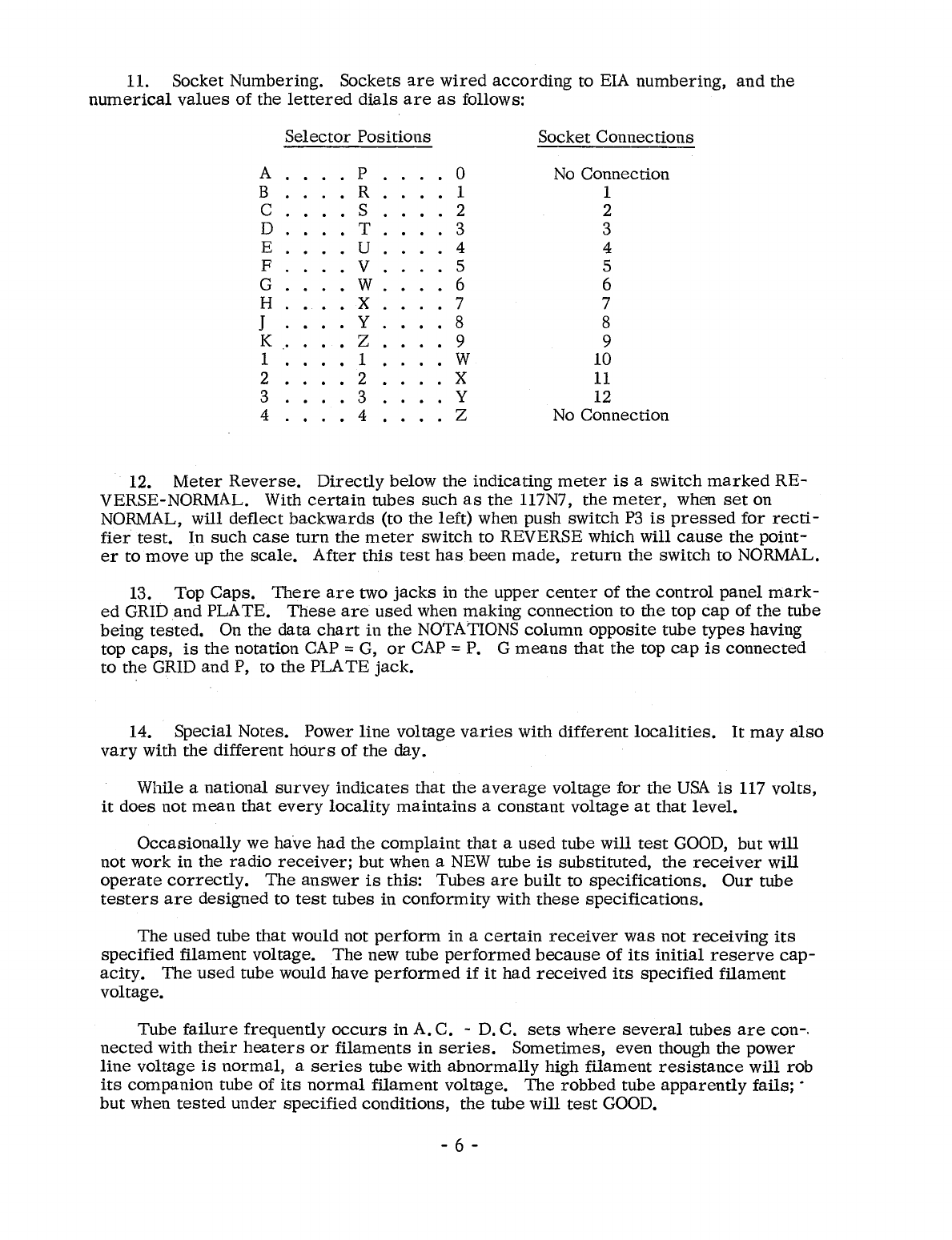
11. Socket
Numbering.
Sockets
are
wired
according
to EIA
numbering,
and
the
numerical
values
of
the
lettered
dials
are
as
follows:
A
B
C
D
E
F
G
H
J
K
1
2
3
4
Selector
Positions
P
R
S
.T
U
V
.W
.X
Y
••
Z
1
••
2
3
. 4
o
1
2
3
4
5
6
7
8
9
W
X
y
Z
Socket
Connections
No
Connection
1
2
3
4
5
6
7
8
9
10
11
12
No
Connection
12.
Meter
Reverse.
Directly
below
the
indicating
meter
is
a
switch
marked
RE-
VERSE-NORMAL. With
certain
tubes
such
as
the
117N7,
the
meter,
when
set
on
NORMAL,
will
deflect
backwards
(to
the
left)
when
push
switch
P3
is
pressed
for
recti-
fier
test.
In
such
case
turn
the
meter
switch
to
REVERSE which
will
cause
the
point-
er
to
move
up
the
scale.
After
this
test
has
been
made,
return
the
switch
to NORMAL.
13. Top
Caps.
There
are
two
jacks
in
the
upper
center
of
the
control
panel
mark-
ed
GRID
and
PLATE.
These
are
used
when
making
connection
to
the
top
cap
of
the
tube
being
tested.
On the
data
chart
in
the
NOTATIONS
column
opposite
tube
types
having
top
caps,
is
the
notation CAP =
G,
or
CAP =P. G
means
that
the
top
cap
is
connected
to
the
GRID
and
P,
to
the
PLA
TE
jack.
14.
Special
Notes.
Power
line
voltage
varies
with
different
localities.
It
may
also
vary
with
the
different
hours
of
the
day.
While a
national
survey
indicates
that
the
average
voltage
for
the
USA
is
117
volts,
it
does
not
mean
that
every
locality
maintains
a
constant
voltage
at
that
level.
Occasionally
we
have
had
the
complaint
that
a
used
tube
will
test
GOOD,
but
will
not
work
in the
radio
receiver;
but
when a
NEW
tube
is
substituted,
the
receiver
will
operate
correctly.
The
answer
is
this:
Tubes
are
built
to
specifications.
Our
tube
testers
are
designed
to
test
tubes
in
conformity
with
these
specifications.
The
used
tube
that
would not
perform
in a
certain
receiver
was
not
receiving
its
specified
filament
voltage.
The
new
tube
performed
because
of
its
initial
reserve
cap-
acity.
The
used
tube would have
performed
if
it
had
received
its
specified
filament
voltage.
Tube
failure
frequently
occurs
in A.
C.
-
D.
C.
sets
where
several
tubes
are
con-.
nected
with
their
heaters
or
filaments
in
series.
Sometimes,
even
though the
power
line
voltage
is
normal,
a
series
tube with
abnormally
high
filament
resistance
will
rob
its
companion tube
of
its
normal
filament
voltage.
The
robbed
tube
apparently
fails;
.
but
when
tested
under
specified
conditions,
the
tube
will
test
GOOD.
- 6 -

The
Model 539C
is
valuable
in
matching
tubes
for
push-pull
stages
and
other
appli-
cations
where
matched
tubes
are
essential.
15.
Life
Test.
The
Model 539C DYNAMIC MUTUAL CONDUCTANCE TUBE
TES-
TER
is
equipped with a
special
feature
to
enable
Life
Test
to
be
made
on
the
tube. In
the
center
of
the
control
panel
is
a
switch
designated
CATH.
ACT.,
NORM.
and
TEST.
While
holding
everything
else
at
normal
this
switch
reduces
the
filament
voltage
by
10%.
a.
Measure
the
mutual
conductance
in
the
ordinary
way with
switch
set
on
NOR-
MAL.
b.
Throw
the
CATH.
ACT.
switch
to
TEST
position.
The
mutual
conductance
should
not
drop
more
than 20%.
c.
After
making
life
test
return
the
switch
to NORMAL
for
all
other
tests.
In
testing
the
35Z5
and
45Z5
rectifier
tubes
it
is
advisable
to
turn
the
power
off
for
about
15
seconds
after
throwing
the
CATH.
ACT.
switch
to
TEST
to allow
the
cathode
to
cool.
Then
turn
the
power
on
and
note
new
reading
of
the
meter.
16.
Self
Bias.
Provision
is
made
to
test
tubes
under
self
bias
condition. In
the
up-
per
edge
of the
control
panel
are
two binding
posts
designated
SELF
BIAS.
These
posts
are
normally
shorted
by
an
attached
bar.
To
use
SELF
BIAS,
connect
a
suitable
bias
re-
sistor
together
with
an
electrolytic
capacitor
of
2000
I.Ltd
in
parallel
across
these
binding
posts.
The
positive
terminal
of
the
capacitor
should
be
connected
to
the
positive
binding
post.
The
toggle
switch
in
the
upper
left
of the
control
panel
is
thrown
from
NORMAL
po-
sition
to the
SELF
BIAS
position.
The
bias
volts
under
self
bias
condition
depends
upon
the
value
of
the
resistor
inserted
between
the
self
bias
posts
mentioned
above,
and
also
upon
the
plate
current
flowing.
Tube
handbooks
can
be
used
as
a
guide
to
the
value
of
the
self
bias
resistance
to
use.
When
completing
the
self
bias
test,
reconnect
the
two binding
posts
by
the
normal
short-
ing
bar
and
throw
the toggle
switch
back
to
the
NORMAL
position.
17.
Plate
Current.
In the
upper
center
of
the
control
panel
are
two
posts
designated
PLA
TE
CURRENT.
These
posts
are
normally
shorted
by
an
attached
bar.
A
suitable
low
resistance
D.
C.
milliammeter
connected
across
these
posts
will
measure
the
plate
current
flowing
through
the
tube being
tested.
Connect
the
positive
terminal
of
the
meter
to
the
positive
binding
post.
NOTE
A
D.
C.
milliammeter
connected
into
the
SELF
BIAS
circuit
will
measure
the
total
cathode
current.
In
measuring
rectifier
tube
current
the
meter
reading
must
be
multiplied
by two,
because
rectifier
tubes
conduct
only
during
a
positive
half-cycle,
whereas
the
meter
integrates
over
a
complete
cycle.
In
checking
thyratrons
such
as
the
884
and
885,
the
bias
voltmeter
should
be
set
initially
at
its
highest
negative
value
(about 40
volts).
The
designated
button
is
held
down
while
the
bias
voltage
is
gradually
reduced
until
the
tube"
strikes",
that
is,
begins
to
con-
duct, which
is
indicated
by a
sudden
deflection
of
the
meter.
The
chart
indicates
the
ap-
proximate
voltage
at
which the
tube
strikes.
There
may
be
a
small
variation
above
or
be-
- 7 -
low
the
given
striking
voltage.
The
meter
indication for a good tube
is
above the point
designated
"RECTIFIERS OK".
18.
Filament
and
Heater
Continuity.
1.
Turn
the
tester
on.
2.
Set the
selectors
as
per
chart
for
the tube to
be
tested.
3. Set
the
FILAMENT switch on BLST
instead
of
voltage
indicated
on
the
chart.
4. Set
the
SHORT
TEST
switch
on
position
5.
5.
Place
the
tube in the
proper
socket.
If
the neon
lamp
glows,
the
filament
is
good
and
a
complete
test
should then
be
made
on the tube, by
setting
FILAMENT
switch
on the
proper
tap,
and
while the tube
heats,
rotate
the SHORT TEST SWITCH
several
times
thru
1 to 5
positions.
If
no
shorts
are
in-
dicated,
set
the
switch in TUBE
TEST
position
and
proceed
to
test
the
tube
as
per
chart.
If
the neon
lamp
does not glow, the
filament
is
open
and
further
test
is
unnecessary.
Certain
tubes
such
as
the
35Z5-50Z7,
etc.,
with tapped
filaments
have
special
continuity
test
settings;
see
roll
chart.
NOTE
It
sometimes
happens
that
a
filament
will show
con-
tinuity when cold, but will open when
it
warms
up.
19. Voltage
Regulator
Tubes.
a.
Set
the
selectors
for
V.
R. tube to
be
tested.
The
test
data
for
V. R.
tubes
will
be
found
at
the top
end
of
the
roll
chart.
For
example,
the
OA3.
b.
Set
FIL
VOLTAGE switch to
OFF.
c.
Set
selector
switches
to AP-0502-0.
d. Set function
switch
on
range
H,
V. R. TEST.
e.
Turn
the
bias
volts
toggle switch to V. R.
volts
and
mils.
f.
Turn
V.
R.
volts
knob fully
counter
clockwise.
g.
Turn
power
adjust
knob fully
clockwise.
Press
P4-LOCK.
h.
Place
V.
R. tube in
proper
socket
and
turn
power
ON.
i.
Turn
V.
R.
voltage
control
knob slowly
clockwise.
The
large
Gm
meter
should
start
to
read
d.
c.
volts
on
the
0-200
volt
scale.
j.
Example: In the
notations
column
for
the
OA3
tube
appears,
"Starts
at
about
100 Volts -Regulation = 5
volts
from
5 to 40 mao
".
In
the
column
marked
MIN. MUT.
CONDo
is
the nominal
operating
voltage for
this
tube -75V.
k. When
the
V. R. tube
strikes
as
explained in (j) above, the
voltmeter
reading
will drop
back
to
operating
voltage.
The
V. R.
current
is
read
on
the
0-100
- 8 -
m.
a.
range
of
the
bias
meter.
1.
For
the
OA3
example
adjust
the
m.
a.
current
from
5
to
40
milliamperes
by
turning
the V. R.
volts
and
mils
knob.
The
OA3
tube
should-not
exhibit
a
voltage
change
of
more
than 5
volts.
m.
When
completing
a
V.
R. tube
test
unlock P4
push
button.
20.
Ohmmeter
Feature.
The
Model 539C
tube
tester
can
be
used
as
a
utility
ohm-
meter
as
follows:
a.
Set
the
SHORTS
switch
on
position
B.
b.
Connect
two
prod
leads
into
the
grid
and
plate
jacks
in
the
center
of
the
con-
trol
panel.
The
red
plate
jack
will
be
the
positive
lead.
c.
Touch
together
the
two
prods
and
adjust
the
ohmmeter
pointer
to
zero.
Re-
sistance
up to 50
megohms
can
be
read
directly
on
the
megohm
range.
d.
Electrolytic
capacitors
can
be
checked
for
leakage.
Observe
that
the
red
(plate)
jack
is
connected
to
the
positive
pole
of
the
capacitor.
21. NORMAL-LOW
Plate
Volts.
In
the
NOTATIONS
column
of
the
data
chart
for
some
tubes
will
be
found PLATE VOLTS =LOW.
This
notation
indicates
that
the
PLATE
VOLTS
switch
located
just
above
the
FUNCTION
switch
is
to
be
set
on
the
LOW
position.
Return
the
switch
to NORMAL
for
all
other
tubes.
22.
Heater
-
Current.
In
the
lower
right
hand
corner
of
the
panel
will
be
found two
binding
posts
which
are
normally
connected
together
by
a
jumper.
By
removing
this
jumper
and
connecting
a
suitable
Milliammeter
or
Ammeter
between
these
two binding
posts,
the
indicating
instrument
will
read
the
current
being
drawn
by
the
heaters
of
the
tube
under
test.
The
actual
voltage
at
the
tube
under
test
will
be
the
voltage
as
indicated
by
the
fila-
ment
selector
switch
minus
the
voltage
drop
across
the
indicating
Milliammeter
or
Am-
meter.
This
voltage
will
generally
be
of
a
very
low
magnitude,
but
can
be
calculated
by
mUltiplying the
current
normally
drawn
by
the
tube
under
test
by
the
impedance
of
the
meter
connected
in
series
with
this
tube,
or
it
can
be
actually
measured
with
a
sensitive
AC
Voltmeter.
If
the
impedance
of
the
meter
is
much
more
thanO.
2
ohms,
the
voltage
drop
might
be
appreciable
percentage-wise
to
the
voltage
delivered
to
the
tube.
For
example,
if
the
current
at
the
tube
is
normally
0.6
amperes,
and
the
impedance
of
the
current
measuring
instrument
were
O.
5
ohms,
the
resultant
loss
would
be
the
product
of
these
two,
or
O.
3
of
one volt.
23. Pilot
Lamp
Testing.
The
center
of
the
large
7-pin
socket
is
used
to
check
pilot
lamps.
Set
the
filament
selector
switches
on HR.
Set
the
filament
voltage
switch
to
the
proper
voltage
for
the
lamp
being
tested.
- 9 -

TO
TEST
BALLAST TUBES
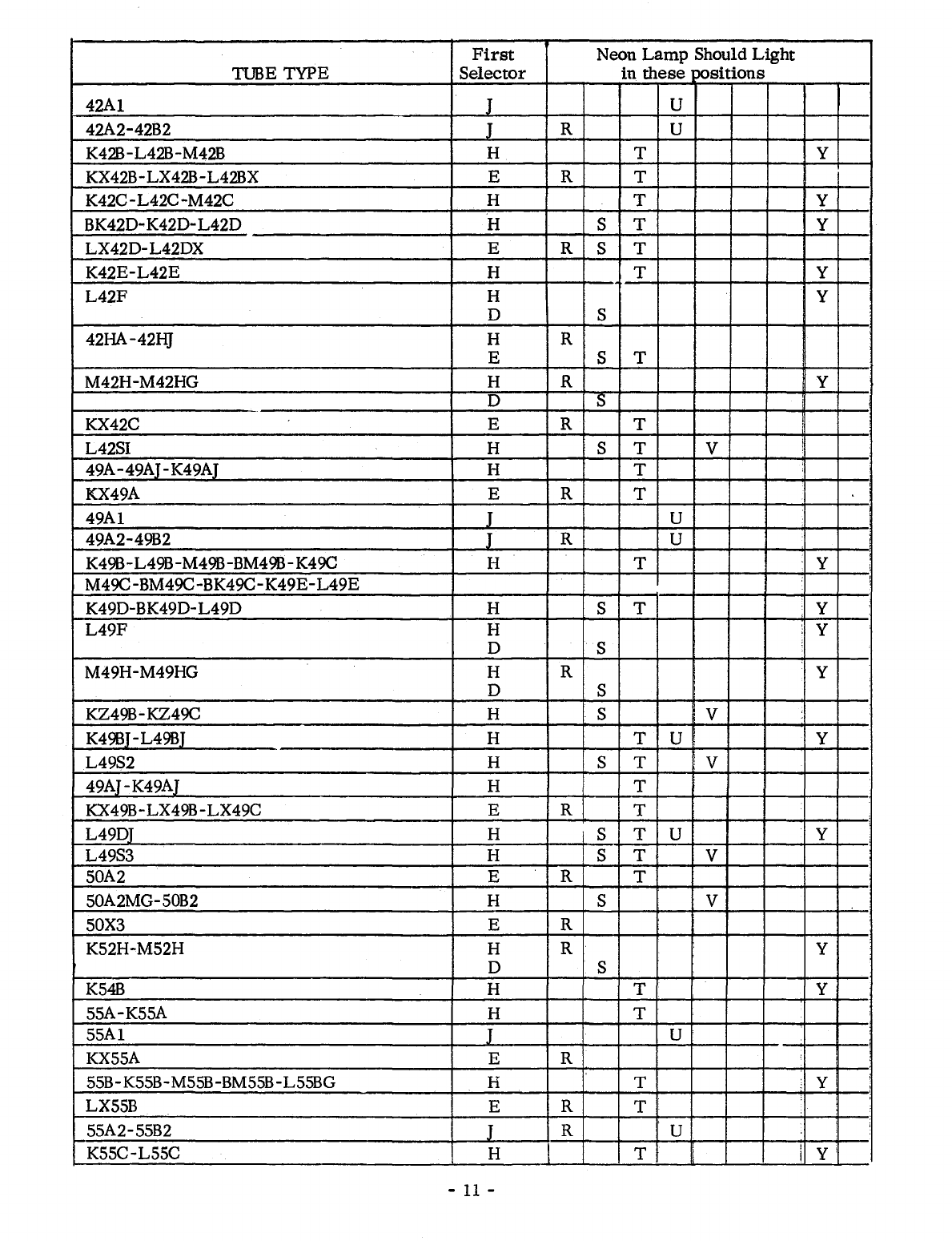
1.
Turn
Tester
on.
2. Set
filament
switch
to BLST.
3. Set SHORT
TEST
switch
on
5.
4. Set
first
selector
switch to
letter
shown
in
column
marked
(first
selector
switch). Set
all
numbered
selectors
on
zero.
5. ROTA
TE
second
selector
switch. NEON LAMP SHOULD LIGHT IN POSITIONS NOTED.
First
Neon
Lamp
Should
Light
TUBE TYPE
Selector
in
these
positions
1A1-IB1-1C1-1E1-1F1-1G1-1]I-lK1-1V1
E R
1Y1-1Z1
IL1-1N1-1P1-1QI-1R1G-1SIG-1
T1G-1U1G H S
2 E R
2UR224 H T Y
2LR212 J R S U
3 E R
03G
H T
4-5
E R
6-133 H T
6-6AA-7-8-9
E R
10A-lOAG H T
lOAB
E R
Kl7B-M17C-BM17C H T Y
M17HG-M17H H R Y
D S
K23B-K23C H T Y
KX23B
E R T
KX30C E R T
M30H H R Y
D S
30A-K30A H T
K30D H S T Y
33A-33AG H T
K34B
H T Y
36A H T
K36B-BK36B-L36B-L36C H T Y
KX36Z E R
KX36C E R T
36D-L36D H S T Y
L360T H R S T U Y
K36H-M36H-M36HG H R Y
D S
40A1 H S
L40SI-L40S2 H S T V
42A
H T
-10 -
First
Neon
Lamp
Should
Light
TUBE TYPE
Selector
in
these
;x>sitions
42AI
J U
42A2-42B2 J R U
K42B
-L42B-M42B H T Y
KX42B-LX42B-L42BX E R T
K42C-L42C-M42C
H T Y
BK42D-K42D-
L42D
H S T Y
LX42D-L42DX E R S T
K42E-L42E
H T Y
L42F
H Y
0 S
42HA-42HJ H R
E S T
M42H-M42HG H R
,y
0 S
KX42C E R T !
L42S1 H S T V i
49A-49AJ-K49AJ H T
KX49A E R T
49AI
J U
49A2-49B2 J R U
K49B-L49B-M49B-BM49B-K49C H T y
M49C-BM49C-BK49C-
K49E-
L49E
,
K49D-BK49D-
L49D
H S T Y
L49F
H Y
0 S
M49H-M49HG H R Y
0 S
KZ49B-KZ49C H S ; V
K49BJ
-L49BJ H T U Y
L49S2 H S T
:V
49AJ-K49AJ H T
KX49B-LX49B-LX49C E R T ,
L49DJ H S T U Y
L49S3 H S T V
50A2 E R T
50A2MG-50B2 H S V
50X3 E R
K52H-M52H H R Y
0 S
K54B
H T Y
55A-K55A H T
55Al
I
U'
KX55A E R
55B-K55B-M55B-BM55B-L55BG H T Y
LX55B E R T ;
55A2-55B2 J R U ;
K55C-L55C H T
Ii
I y
I
-
11
-

First
Neon
Lamp
Should
Light
TUBE TYPE
Selector
in
these
?Ositions
KXSSC E R T
KSSCP H T V Y
KSSD-LSSD H S T Y
LSSE-MSSE H T Y
LSSF-MSSF-BLSSF H Y
D S
KSSH-MSSH-MS5HG H R Y
D S
LSSSl-LS5S2 H S T V
60R30G E R T
64.23
H T
-
67A H T
K67B-L67B H T Y
L73B-K74B-L74B H T Y
KX74C E R T
80A H T
K79B-K800-K8OC-L80B H T Y
KX80B
E R T
K80F H Y
D S
KX87B-LX87B E R T
L90B H T Y
K90F-M90F-K92F-M92F
H Y
D S
92A H T
L92B-95K2 H T Y
L99D
H S T Y
lOOR8
E R T
120R E R
120R8 E R T
13SK1 H T Y
13SK1A H T U Y
140L4-140L8-140R4-140R8
E R T
140R E R
140L44 E R T
140R44 E R S T
16SL4-16SR4-16SR8 E R T
16SR E R
16SL44-16SR44 E R S T
18SL4-185L8-18SR4-18SR8 E R T
185R E R
18SL44-185R44 E R S T
200R-2S0R E R
2S0R8 E R T
290L4 E R T
300R4-320R4 E R T
340 E R
R08-1
H T U Y
-12 -

First
Neon Lamp Should Light
TUBE
TYPE
Selector
in
these
positions
E14980-W43357-W45788-3613
H T Y
3334-3334A
H S T Y
-
3613 H T Y
8593-8598-8601-8664
H T Y
3CR241
H S T Y
3ER248
H S T U y
--
B9M15822 C T
E V
G X Y
B9M16067 H S T V W y
1B9M16275 C T U V W X Y
1B9M16534 H S T V W y
B9M17571 J S T
H U V Y
B9M18941 C R T
E V
G X Y
17A470303 H R S V
J W
E T
17A485459 H R S W
E T
TBR102D-TBR104D C R T U V
G X Y
TBR103D C R U V
G X Y
397021 C R T
-'
397022
E V W
397023 H Y
397036
. B V
R S V
r-.
407100,
H
408100 H R S V
D U
gYl407300 H S T V W Y
571606 C R T
E V W
H Y
-13 -
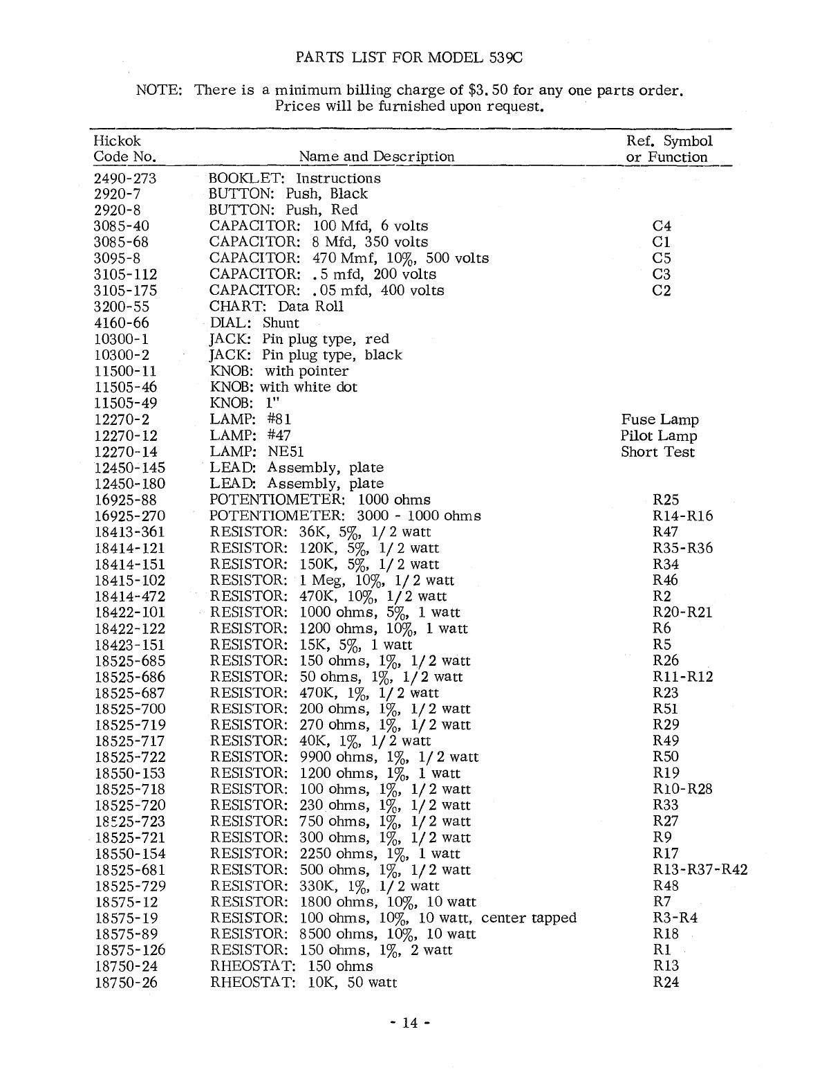
PARTS LIST FOR MODEL 539C
NOTE:
There
is
a
minimum
billing
charge
of
$3. 50
for
anyone
parts
order.
Prices
will
be
furnished
upon
request.
Hickok Ref. Symbol
Code
No.
Name
and
Description
or
Function
~~--------------~~-~~~~~~~------.-------------~~~~~
2490-273 BOOKLET:
Instructions
2920-7 BUTTON: Push, Black
2920-8 BUTTON: Push,
Red
3085-40
CAPACITOR: 100 Mfd, 6
volts
3085-68 CAPACITOR: 8 Mfd, 350
volts
3095-8 CAPACITOR: 470 Mmf,
10%,
500
volts
3105-112 CAPACITOR:
.5
mfd, 200
volts
3105-175 CAPACITOR:
.05
mfd,
400
volts
3200-55
CHART: Data Roll
4160-66 DIAL: Shunt
10300-1 JACK: Pin plug type,
red
10300-2 JACK: Pin plug type,
black
11500-11
KNOB:
with
pointer
11505-46
KNOB:
with
white
dot
11505-49
KNOB:
1"
12270-2 LAMP: #81
12270-12 LAMP: #47
12270-14 LAMP: NE51
12450-145 LEAD:
Assembly,
plate
12450-180 LEAD:
Assembly,
plate
16925-88 POTENTIOMETER: 1000
ohms
16925-270 POTENTIOMETER: 3000 -1000
ohms
18413-361 RESISTOR: 36K,
5%,
1/2
watt
18414-121 RESISTOR: 120K,
5%,
1/2
watt
18414-151 RESISTOR: 150K,
5%,
1/2
watt
18415-102 RESISTOR: 1 Meg,
10%,
1/
2
watt
18414-472 RESISTOR: 470K,
10%,
1/2
watt
18422-101 RESISTOR: 1000
ohms,
5%,
1
watt
18422-122 RESISTOR: 1200
ohms,
10%,
1
watt
18423-151 RESISTOR: 15K,
5%,
1
watt
18525-685 RESISTOR: 150
ohms,
1%,
1/2
watt
18525-686 RESISTOR: 50
ohms,
1%,
1/2
watt
18525-687 RESISTOR: 470K,
1%,
1/2
watt
18525-700 RESISTOR: 200
ohms,
1%,
1/2
watt
18525-7l9
RESISTOR: 270
ohms,
1%,
1/2
watt
18525-717 RESISTOR: 40K,
1%,
1/2
watt
18525-722 RESISTOR: 9900
ohms,
1%,
1/2
watt
18550-153 RESISTOR: 1200
ohms,
1%,
1
watt
18525-7l8
RESISTOR: 100
ohms,
1%,
1/2
watt
18525-720 RESISTOR: 230
ohms,
1%,
1/2
watt
18::25-723 RESISTOR: 750
ohms,
1%,
1/2
watt
18525-721 RESISTOR: 300
ohms,
1%,
1/2
watt
18550-154 RESISTOR: 2250
ohms,
1%,
1
watt
18525-681 RESISTOR: 500
ohms,
1%,
1/2
watt
18525-729 RESISTOR: 330K,
1%,
1/2
watt
18575-12 RESISTOR: 1800
ohms,
10%, 10
watt
18575-19 RESISTOR: 100
ohms,
10%,
10 watt,
center
tapped
18575-89 RESISTOR: 8500
ohms,
10%, 10
watt
18575-126 RESISTOR: 150
ohms,
1%,
2
watt
18750-24 RHEOSTAT: 150
ohms
18750-26 RHEOSTAT: 10K, 50
watt
-14 -
C4
Cl
C5
C3
C2
Fuse
Lamp
Pilot
Lamp
Short
Test
R25
R14-R16
R47
R35-R36
R34
R46
R2
R20-R21
R6
R5
R26
R11-RI2
R23
R51
R29
R49
R50
R19
R10-R28
R33
R27
R9
R17
RI3-R37-R42
R48
R7
R3-R4
R18
Rl
R13
R24

PARTS LIST FOR MODEL 539C
NOTE:
There
is
a
minimum
billing
charge
of
$3. 50
for
anyone
parts
order.
Hickok
Code No.
19350-1
19350-113
19350-364
19350-367
19350-365
19350-381
19350-383
19350-76
19350-93
19350-94
19350-95
19350-
96
19350-97
19350-98
19350-220
19910-61
19911-7
19911-55
19912-480
19912-479
19912-202
19912-304
19912-308
19912-312
20800-103
20800-169
20875-6
20875-28
Emission
Grid
Control
and
Gas
Test
Prices
will
be
furnished
upon
request.
Name
and
Description
SOCKET: Bayonet
for
81
Lamp
SOCKET: Bayonet Neon
and
Pilot
Lamp
SOCKET: 10 pin
SOCKET: Novar
SOCKET:
Compactron
SOCKET:
Nuvistor,
5 pin
SOCKET:
Nuvistor,
7 pin
SOCKET: 7 pin
miniature
SOCKET: 4 pin
SOCKET: 5 pin
SOCKET: 6 pin
SOCKET: 7 pin
SOCKET: Lokta1
SOCKET: Octal
SOCKET: Subminiature, combination 7
and
8 pin
SWITCH: Gang, 8
buttons
SWITCH:
Meter
reverse
SWITCH: Toggle DP-DT
SWITCH:
Suppressor
and Cathode
SWITCH:
Selectors
SWITCH:
Filament
Volts
SWITCH: 3 P-
DT
SWITCH: Function
SWITCH:
Short
Test
TRANSFORMER:
Filament
TRANSFORMER:
Plate
TUBE:
5Y3GT/G
TUBE:
83
TESTING TELEVISION PICTURE TUBES
WIlli
lliE
CRT-1
ADAPTER
Selectors
Fil
Bias Shunt
HS-3508-4
6.3
o G
Ref. Symbol
or
Function
Press
PI
Good
tubes
should
read
above
line
marked
RECTIFIERS
AND
DIODES
OK.
HS-5308-4
6.3
* D P5
* Hold down P5
and
rotate
Bias knob.
Meter
should
move
up
and
down
scale
if
grid
is
operation.
GAS
TEST: Hold down
P5
and
adjust
bias
until
meter
reads
one
small
division. While holding
P5
down,
press
P6.
If
meter
pointer
moves
up
scale
more
than one division, tube
is
gassy.
NOTE: In
ordering
parts
or
materials
for
this
instrument,
the
serial
number
must
be
given in
order
to
identify
properly
the
material
required.
-
15
-

01
I.
BINDING POSTS
FOR
INSERTING METER
TO
READ
~ER
CURRENT
el17
~
.75
.50
.35
~
.25
,r1
NORMA
L C
.20
TEST
!
~
o-:¥-
~
+
0R-
_ACT.
~
~
~
r-
~
~
03
<>
*
50
~
*
I-
*
~
*
~
04
50
~
~
.
BLS
OFF
g PILOT
LAMP
0 J 0
20
K
06
r--r"
L 1.2K
Pl70
M
N
170 0
F>
~5
P
~
I~~A
$
FUSE
~
lAMP
~
0
:
l~'·o
c.< S
ON
l-
F
OFF
1~160
G
POWER
1~
__
160
ri'f3f
3
0 H
~
C
r"=/
1~5
015
I~
50
E
ni
?
014 r- RI6
IK
?3K
I
I
~
L_
--
-
l@
E1
8.5K
RIO
1·2K
f4--
IIII
I-
l-
022
600
020
IK
02
i~L7
470K
?rl
P6
053
~
01
150 L
r;=:F-
ru~es
P5
~;~
P4
LOCK
Ir:
~~~
P4
NON
LOCK
HI-
LOW
PLATE
VOLTS
r.b:~TL.
~~r~
~
Ir
0
~I
II
I
~[~
~27UF
07
[.BK
1\
-
052
~go
fbOo
Oil
012
500
50
50
I
I
oa;.9
I
~~
~
BIAS
SECTION
RANGE
~
~'«'!Q.H
;.2..
_I
~
~~
~o
REAR
f-o:
f{
0
SEC110NS' o °
o 0
023 024
R49
~
470K
10K
40K
~
~
OEV
:
NORI
I-
~ R50
021 BUF 9.9K
"
~
=ftJ
051
(-------I-,;;:LF
BIAS
200
<
QMI
~j
02
40
0'
'"
0'
0 d 0
0'
60
SELECTOR
NO.
I
(FILAMENT
POS.)
0°00°0
"@"
o 0
~
0
~
O 0
o
:t
0
Oo
0
o 0
v)J
~\\1;
~'V~
~fr~~
I J 00
FUNCTION
SW~TCH
,
,
---
--
--
-'
, I
, I
o~;
1:
~
:0«i
o, 0 o ,
~~
f
~
o , 0
o 0 0
0:=
o 0
000
~
0°
°
00
0
0°
°0
9.~
~'i&
~
~©~
~o
00
~
&1>0
00°
00
OS
II
R37
R3B
R39
040
15K
500
60
40
40
'V
~'~
~L
~~
R43
R44
198 2
~
I
PANEL
LAMP
TEST
SOCKET
~
OCTAL
/0,,0
ffi,;;
O)Q~O
f1:.5;
S(LECTOR
NO.2
(FILAMENT
NEQ
0°00°0
"@"
f 0 }
00
:)
00
o 0
00 0
~~1
~~ :~
~~~~
f(f
00
-:=J
025
I.
026
150
-f-
R27
750
r--
- - -
,
C6
,
GR)~
~~
R2B
o, 0 100
WaoO
r-
020
270
I-
~
033
230
~O
C3
.05.L1f
041
R42
60
500
'V
LOCTAL
o,q
f'~
~;
.......---
r--
,---
r-
II
•
.!
-
~
~
o 0
o 0
o
b.2-
W
lEo~
-
t
LOCTAL
O'C?
~")
~;
II
=
==
=1-
-
.~
-I"'
~
o 0
°0
~~
u,
IW
NOVAL 8 PIN
IiOlf
~
SUB
MiN.
SPIN
NUVISTOR
--"7ci
~
P"\
0.'
GO
0,
70
ff-i0
O.
10
o 0
00
0
·0
~)
0
~,
'~I?~~
SHORTING
BAR
ACROSS POSTS
FOR INSERTING
SELF
BIAS
O'~
~.6'I
IN
LINE
~
I~
6
{,
&6
&<11
0'
'0
010
'20
~
JIll
~
SHORT TEST
SWITCH
/
/
SELECTOR
NO.4
(PLATE)
0
000
0
0
0
~u~
rK~~~~
~
(1
00
R4S
IMEG
"!~
IOOllF
6W.Y,
J.lMHO
METER
1.5K
11511A
-----
______
,_.L
____
-1------,.-------
~o~
/
/
~~
O~
I~~o
r!L
o 0
~-~
0
~
00~
°O:~
°O:~
o :0-
0"
0
0
00
°
P--
t-<"
0 0
00
I~<
R47
~
LiI~
t 36K
O~O
O~O
......;.;)l:;
io.i
0
.0'
R480:~
-oJ
0
To
00
°OOb
O~
330KO
00
0
.....
..........,
~
0
.3.
:..
R.,
HI
150~
~
NOISE
TES{f
C5
2501<
1
R36
I
470
120K
500V
I
~I
'~35
T
II
120K
NE-51
~NOVAR
COMPACTRON
q
'?60~
~~~9P90:-
0,
70
0'
'0
0'
"0
rr-:
0
rff!~O
SELECTOR
NO· 5
(SCREEN)
0
0\
0°
000
~~~
~
~~
~
rr~~
-.l
I
PLATE
@..
I-
~~~~:~N:,:O~~G'
~~
POST FOR
INSERTING
METER
TO REAO
PLATE
CURRENT.
~
GRID
CAP
R32
.7
I--
7PIN
NUVISTQFI
INJ
Ito
~
=
~
'0
ill
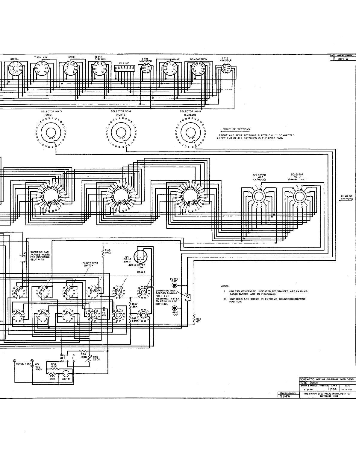
• FRONT OF SECTIONS
FRONT
ANa
REAR
SECTIONS
ELECTRICALLY
CONNECTED.
*LEFT
END OF
ALL
SWITCHES
IS
THE
KNOB
END.
SELECTOR
SELECTOR
NO.6
NO
7
(CATHODE)
(SUPPR[:;:'uHl
~cQa
~OO
NOTES
I.
UNLESS
OTHERWISE INDICATfD,RESISTANCES ARE
IN
OHMS.
CAPACITANCES
ARE
IN
PICOFARADS.
2.
SWITCHES
ARE
SHOWN
IN
EXTREME
COUNTERCLOCKWISE
POSITION.
SCHEMATIC
WIRING
DlAGRA
TUBE TESTER
DIlAIIlI.TRACEO
CH[CKEO
""1"0
984W
984
W
RlAR
O~
~S
Table of contents
Other Hickok Test Equipment manuals


