Secure Home Heath Zenith SH-4132-MB User manual

© 2020 HeathCo LLC 207738-03A
INSTALLATION AND OPERATING
INSTRUCTIONS
SAFETY INFORMATION ......................................2
PREPARATION ...............................................2
HARDWARE CONTENTS......................................2
LIGHT FIXTURE INSTALLATION...............................3
WIRING THE LIGHT FIXTURE .................................4
OPTIONAL WIRING ..........................................5
MOUNTING THE LIGHT FIXTURE .............................6
TESTING AND ADJUSTMENTS................................6
CARE AND MAINTENANCE...................................8
TROUBLESHOOTING GUIDE..................................8
SPECIFICATIONS.............................................8
TECHNICAL SERVICE.........................................9
THREE YEAR LIMITED WARRANTY............................9
Motion Decorative Light Questions?
Please refer to the troubleshootingguide in this manual
or call our technical service department (English speak-
ing only) at 1-800-858-8501, 8:00 a.m. - 5:00 p.m., CST,
Monday - Friday before returning to your retailer.
Keep this manual for future reference.
ATTACH YOUR RECEIPT HERE
Receipt is required for all warranty requests.
Purchase Date
Item Model
616281 SH-4132-MB
Motion Sensing Decorative
Light

2207738-03
SAFETY INFORMATION
Please read and understand this entire manual before at-
tempting to assemble, operate, or install the product.
is light xture requires 120-volts AC.All wiring must be
in accordance with the National Electrical Code (Canadian
Electrical Code in Canada). Some local electrical codes
require installation by a qualied electrician.
WARNING
• Turn power o at circuit breaker or fuse when
wiring xture or replacing bulbs. Place tape over
circuit breaker switch and verify power is o at
the xture.
CAUTION
• Do not cut any wires that have factory installed
wire connectors or remove the wire connectors.
PREPARATION
Beforebeginning installation of product,makesureall parts
are present. Compare parts with hardware contents list. If
any part is missing or damaged,do not attempt to assemble,
install, or operate the product.
ToolsRequired forAssembly(not included): Phillips and
athead screwdrivers, pliers, wire strippers/cutters, multi-
meter, electrical tape, silicone sealant, safety glasses, work
gloves, and ladder
• Foreasy installationandtooperatethelightusing Manual
mode, replace an existing light xture operated by a wall
switch.
• Do not connect to dimmers or timers.
• For best performance,mount xture about 6 feet (1.8 m)
above the ground.
Estimated Installation Time: 30 minutes
3x – Wire Connectors
2x – Mounting
Bracket Screw
A - (1x) Mounting Bracket
B - (2x) Fixture Mounting
Screws
C - (2x) Decorative Nut
(This assembly is attached to
the rear of the lantern canopy.)
HARDWARE CONTENTS
Note: Illustrations may vary from actual unit.
A
B
C

3207738-03
Wire Path
Ground Screw
Mounting
Plate
LIGHT FIXTURE INSTALLATION
For bestperformance,mount the xtureabout 6feet(1.8m)
above the ground.
1. Remove two decorative nuts.
2. Remove mounting plate.
3. Tighten mounting screws nger tight.
4. Attach mounting plate to junction box.
Decorative Nut
Mounting Screw
Bracket
Mounting
Screws Mounting Plate
Junction
Box
Note: We recommend having an assistant help hold the
lantern assembly during the wiring process.
is xture comes with a universal mounting bracket. It is
pre-assembled on the xture to t the majority of junction
box applications.
If the slots on the mounting plate do not line up with the
junction box screw holes, follow these steps:
1. Removethexturemounting screwsfromthemounting
plate. Note: Do not remove the ground screw.
2. Attach ground wire “pigtail” to ground screw on
mounting plate (See
Recommended Grounding Method
for additional information).
3. Flip the mounting plate over.
4. Rotate the mounting plate so the wire path is on the
upper right.Note: e wire path on the mounting plate
must be located as shown below to allow the wires on
the back of the xture to pass through.
5. Reinstall the xture mounting screws and attach the
mounting plate to the junction box as shown.
Wire Path
As Shipped Flipped and
Rotated
Wire Path
Fixture Screws
Ground Screw

4207738-03
Black to black
White to white
Recommended Grounding Method
Use a green ground “pigtail” (not provided) and twist
one end together with the bare xture wire and the box
ground wire. Secure with a wire connector. Secure the
other end of the “pigtail” with the GND screw on the
mounting plate.
WIRING THE LIGHT FIXTURE
CAUTION: DO NOT connect the RED wire
unless you want to control other lights from the
motion sensor (see Optional Wiring).
Note: All wiring must be run in accordance with the Na-
tional Electrical Code through conduit or another accept-
able means. Contact a qualied electrician if there is any
question as to the suitability of the system.
WARNING: Turn power o at circuit breaker
or fuse.
Connect the xture wires to the wires in the junction box.
Twist the wires together and secure with wire connectors.
Ifyouhave ametaljunctionbox,youmaynot need the green
“pigtail”. If you are unsure about the grounding method,
consult your local building code.
One Motion Light
Two Motion Lights
Black
White
Green
or Bare
Copper
Green
or Bare
Copper
Light
Fixture
Black
White
Light
Fixture
Light
Fixture

5207738-03
Green
or Bare
Copper
Green
or Bare
Copper
Green
or Bare
Copper
OPTIONAL WIRING
is xture is provided with a sensor rated for 500 Watts.Since the xture is only rated 60 Watts,440 Watts of additional
lighting may be controlled by this sensor.
When determining what a xture is rated for, do not simply look at the rating on the light bulb in the xture. Look at
the marking which species the maximum bulb wattage for which the xture is suitable.
Once you have selected the xtures to be connected and determined their maximum ratings, add these ratings up. For
instance,if you have 3 xtures rated 60 Watts, 150 Watts, and 100 Watts respectively,you have a total load of 310 Watts.
Wiring Diagram 1 – When wiring to control a standard light xture: Strip the motion sensor’s red wire and connect to
the standard light’s black wire.Connect all white wires together.Total xture ratings must not exceed 500 Watts (4.1 A).
Wiring Diagram 2 – When wiring to control another motion sensing light xture (Primary / Controlled): Strip the red
wire in both light xtures. Connect the red wire of the controlling (Primary) xture to the red and black wires of the
controlled (Controlled) xture.Connect all white wires together.Total xture ratings must not exceed 500 Watts (4.1 A).
Wiring Diagram 3 – When wiring so either motion light turns on the both motion lights (Primary / Primary): Strip the
red wire in both light xtures. Connect the red wire of one xture to the red wire of the second xture. Note: In most
installations, an additional wire (same gauge as existing house wire) will have to be installed in the house to connect the
two xtures as Primary / Primary. Connect all white wires together and all black wires together. Total xture ratings
must not exceed 500 Watts (4.1 A).
Black
White
Light
Fixture
Light
Fixture
(Standard)
Black
White
Light
Fixture
Light
Fixture
Red
Red
Wiring Diagram 1 Wiring Diagram 2
Wiring Diagram 3
Black
White
Red
Light
Fixture Light
Fixture
Primary Controlled
Primary Primary

6207738-03
TEST 1 5 10 MIN
ON-TIME
LO - M - HI
SENSITIVITY
Junction
Box
MOUNTING THE LIGHT FIXTURE
1. Make sure wire connectors and wires are inside the
junction box.
2. Slide the xture assembly onto the mounting screws.
Tighten decorative nuts removed in step 1 of
Light
Fixture Installation
section securely against xture base.
Mounting Screw
Decorative Nut
3. Installonemedium base light bulb (60Wattmaximum,
tungsten incandescent).
TESTING AND ADJUSTMENTS
Initial Setup
e TEST mode overrides the photocell (daylight shuto
feature) and allows the light xture to be tested day or night
when the ON-TIME switch is in the TEST position.e
light will stay on for 5 seconds after all motion has stopped.
30 ft. (9.1 m)
6 ft. (1.8 m)
150°
5.
Movethesensorheadleftorrighttochangethecoverage
area. Note: Grasp the sensor only as shown and turn
the entire sensor. Any other method may damage
the sensor. Do not force it past the stops.
1. Set the ON-TIME control to TEST.
2. Turn on the circuit breaker or fuse and the light switch.
3. Allow the sensor to completely warm up (90 seconds)
before beginning the setup process.
4. Perform a walk test. Walk in an arc across the front of
the sensor.
Sensor Controls
Maximum Range Maximum
Coverage Angle
(Top View)
Rotating Sensor Head to Change Coverage Area
1
5
0
°
1
5
0
°

7207738-03
Note: When rst turned on wait about 1 1/2minutes for
the circuitry to calibrate.
* resets to Auto Mode at dawn.
Caulking Around Fixture Base
Mode: On-Time Works: Day Night
Test 5 Seconds x x
Auto 1, 5, or 10 Minutes x
Manual To Dawn* x
Final Setup
1.
Adjust the sensitivity (SENS) to increase or decrease
the range as needed. Too much sensitivity may cause
false triggering due to heat sources in the coverage area
(see
Testing and Adjustments or Troubleshooting
section).
2. Set the amount of ON-TIME you want the light to
stay on after motion is detected (1, 5, or 10 minutes).
3. Caulkaround xturebase with silicone weather seal-
ant after all Testing and Adjustments are complete.
Operating Modes
• Motion Sensor (AUTO) – is light xture is designed
to automatically turn on when the sensor detects a tem-
perature dierence moving across the front of the motion
sensor. e light will turn o automatically after a set
amount of time. e ON-TIME control should be set
to 1, 5, or 10 minute setting and the wall switch should
be left in the ON position at all times.
• Manual Mode – is light can be activated to stay on full
bright after dusk (sunset) for only one night at a time. It
automatically resets to motion sensing at dawn (sunrise).
Manual mode must be re-activated each night. Note: If
power to the light xture is o for more than 5 seconds,
allow the electronic circuitry in the sensor to calibrate
(90 seconds) prior to switching to manual mode.
1. To turn on MANUAL mode, switch the light o at
the wall switch for 1 to 2 seconds and then back on.
2. To return to AUTO mode, switch the light o at the
wall switch for 1 to 2 seconds and then back on.
Note: e sensor will also reset to AUTO mode at
sunrise.
Turn Switch OFF for
1 to 2 seconds Turn Switch
Back ON

8207738-03
SPECIFICATIONS
Range ................................................................Up to 30 ft. (9.1 m) [varies with surrounding temperature]
Sensing Angle....................................................Up to 150°
Sensor Aiming Adjustment Angle ....................90°
Electrical Load..................................................Up to 60 Watt Maximum Incandescent
Bulb Type ..........................................................Medium Base,Type “A”, 60 Watt Maximum
Sensor Capacity.................................................Up to 500 Watt (4.1 A) Maximum Tungsten
Power Requirements..........................................120 VAC, 60 Hz
Operating Modes ..............................................TEST, AUTO, and MANUAL MODE
ON-Timer.........................................................1, 5, 10 minutes
Test Timer.........................................................5 Seconds
Manual Mode Timer.........................................Dusk-to-Dawn
SYMPTOM POSSIBLE CAUSE SOLUTION
Lights will not
come on. 1. Light switch is turned o.
2. Light bulb is loose or burned out.
3. Fuse is blown or circuit breaker is turned o.
4. Daylight turn-o is in eect.
5. Sensor not detecting movement.
6. Incorrect circuit wiring, if this is a new installation.
1. Turn light switch on.
2. Check bulb and replace if burned out.
3. Replace fuse or turn circuit breaker on.
4. Recheck after dark.
5. Re-aim the sensor to cover desired area.
6. Verify wiring is correct.
Lights come on in
daylight. 1. Light control may be installed in a relatively dark location.
2. Light control is in TEST. 1. e xture is operating normally under these conditions.
2. Set control switch to 1, 5, or 10 minutes.
Lights come on for
no apparent reason. 1. Light control may be sensing small animals or automobile
trac.
2. Sensitivity is set too high.
1. Re-aim sensor. Reduce sensitivity.
2. Reduce sensitivity.
Lights stay on
continuously. 1. e sensor may be picking up a heat source like an air vent,
dryer vent, or brightly painted, heat-reective surface.
2. Light control is in Manual Mode.
3. Sensitivity is set too high.
1. Re-aim sensor. Reduce sensitivity.
2. Switch to Auto.
3. Reduce sensitivity.
Lights ash on
and o. 1. Light control is in the TEST mode and warming up.
2. Heat being reected from other objects may be aecting the
sensor.
1. Flashing is normal under these conditions.
2. Re-aim sensor. Reduce sensitivity.
Seasonal Temperature Changes – e closer the surrounding temperature is to a person’s body heat, the less sensitive the sensor will appear. e greater
the temperature dierence, the more sensitive the sensor will appear.e SENS control might need to be readjusted toward MIN or MAX as the outside
temperature changes for the dierent seasons.is is a normal part of the light sensor’s operation.
TROUBLESHOOTING GUIDE
CARE AND MAINTENANCE
• To prolong the original appearance, clean with clear water and a soft damp cloth only.
• Do not use paints, solvents, or other chemicals on this light xture.ey could cause a premature deterioration of the
nish.is is not a defect in the nish and will not be covered by the warranty.
• Do not spray with hose or power washer.

9207738-03
TECHNICAL SERVICE
Please call 1-800-858-8501 (English speaking only) for assistance
before returning product to store.
If you experience a problem, follow this guide. You may also want to visit our Web site at: www.hzsupport.com. If the
problem persists, call* for assistance at 1-800-858-8501 (English speaking only), 8:00 AM to 5:00 PM CST (M-F).
You may also write* to:
HeathCo LLC
P.O. Box 90045
Bowling Green, KY 42102-9045
ATTN: Technical Service
* If contacting Technical Service, please have the following information available: Model Number, Date of Purchase,
and Place of Purchase.
No Service Parts Available for this Product
Please keep your dated sales receipt, it is required for all warranty requests.
THREE YEAR LIMITED WARRANTY
is is a “Limited Warranty” which gives you specic legal rights. You may also have other rights which vary from state to state
or province to province.
For a period of three years from the date of purchase, any malfunction caused by factory defective parts or workmanship will be,
at the sole option of HeathCo LLC, either repaired or replaced at no charge to you.
Not Covered - Repair service, adjustment and calibration due to misuse, abuse or negligence, light bulbs, batteries, and other
expendable items are not covered by this warranty. Any damage to the light xture resulting from the use of chemicals or a pres-
sure washer machine are not covered by this warranty. Unauthorized service or modication of the product or of any furnished
component will void this warranty in its entirety. is warranty does not include reimbursement for inconvenience, installation,
setup time, loss of use, unauthorized service, or return shipping charges. HeathCo LLC reserves the right to discontinue products
and to change specications at any time without incurring any obligation to incorporate new features in products previously sold.
Finish Warranty Exclusions - Finishes for xtures installed outdoors are subject to change due to prolonged exposure to sunlight,
pollutants,and other environmental conditions.Metal nishes will naturally mature over time,changing in appearance and creating
a living nish.Painted nishes on outdoor xtures may naturally fade over time,depending on the xture’s exposure to the outdoor
elements.us, any claim for fading, discoloration, or “patina” of a nish on an outdoor xture is not applicable to the above war-
ranty. See “Care and Maintenance”, page 8, for proper cleaning of the xture.
is warranty covers only HeathCo LLC assembled products and is not extended to other equipment and components that a customer
uses in conjunction with our products.
THISWARRANTYIS EXPRESSLY INLIEUOFALLOTHERWARRANTIES,EXPRESSOR IMPLIED,INCLUDING
ANY WARRANTY,REPRESENTATION OR CONDITION OF MERCHANT ABILITY OR THATTHE PRODUCTS
AREFITFORANYPARTICULARPURPOSEORUSE,ANDSPECIFICALLYINLIEUOFALLSPECIAL,INDIRECT,
INCIDENTAL, OR CONSEQUENTIAL DAMAGES.
REPAIR OR REPLACEMENT SHALL BE THE SOLE REMEDY OF THE CUSTOMER AND THERE SHALL
BE NO LIABILITY ON THE PART OF HEATHCO LLC FOR ANY SPECIAL, INDIRECT, INCIDENTAL, OR
CONSEQUENTIAL DAMAGES, INCLUDING BUT NOT LIMITED TO ANY LOSS OF BUSINESS OR PROFITS,
WHETHER OR NOT FORESEEABLE. Some states or provinces do not allow the exclusion or limitation of incidental or
consequential damages, so the above limitation or exclusion may not apply to you.
Please keep your dated sales receipt, it is required for all warranty requests.

10 207738-03
INSTRUCCIONES PARA SU INSTALACIÓN
Y FUNCIONAMIENTO
INFORMACIÓN SOBRE LA SEGURIDAD .....................11
PREPARACIÓN .............................................11
FERRETERÍA OFRECIDA .................................... 11
INSTALACIÓN DEL APARATO DE LUZ ....................... 12
CABLEADO DEL APARATO DE LUZ ......................... 13
CONEXIÓN ALTERNA ...................................... 14
MONTAJE DEL APARATO DE LUZ ........................... 15
PRUEBAS Y AJUSTES....................................... 15
CUIDADO Y MANTENIMIENTO ............................. 17
GUÍA DE INVESTIGACIÓN DE AVERÍAS .....................17
ESPECIFICACIONES ........................................17
SERVICIO TÉCNICO ........................................ 18
GARANTÍA LIMITADA A 3 AÑOS............................ 18
Luz decorativa detectora de movimiento
¿Preguntas?
Por favor, consulte la guía de solución de
problemas en este manual o llame a nuestro de-
partamento de servicio técnico (solo para Inglés) al
1-800-858-8501, de 8:00 am - 5:00 pm, hora central,
de lunes a viernes antes de volverlo a la tienda.
Guarde este manual para referencia en el futuro.
ADJUNTE SU RECIBO AQUÍ
Se requiere recibo para todas las solicitudes de
garantía.
Fecha de compra
© 2020 HeathCo LLC 207738-03 S
Artículo Modelo
616281 SH-4132-MB
Luz decorativa detectora de
movimiento

11207738-03
INFORMACIÓN SOBRE LA
SEGURIDAD
Por favor lea y comprenda todo el manual antes de intentar
ensamblar, operar o instalar el producto.
Esta lámpara requiere de 120 voltios CA.Todo el cableado
debe ser de acuerdo con el Código Nacional de Electricidad
(CódigoEléctricoCanadienseenCanadá).Algunoscódigos
eléctricos locales requieren que la instalación sea hecha por
un electricista calicado.
ADVERTENCIA
• Desconecte la alimentación en el disyuntor o
fusible cuando haga el cableado de la lámpara
o cambie las bombillas. Ponga cinta adhesiva
sobre el interruptor del disyuntor y verique que
la electricidad esté apagada en la lámpara.
PRECAUCIÓN
• No corte ningún cable que tenga conectores
de cables instalados en fábrica ni retire los
conectores.
PREPARACIÓN
Antes de comenzar la instalación, asegúrese de que tiene
todas las piezas.Compare las piezas con la lista de ferretería
ofrecida. Si alguna pieza falta o está dañada, no intente
ensamblar, instalar o utilizar el producto.
Herramientas necesarias para el montaje (no incluidas):
Destornilladores Phillips y de cabeza plana, pinzas, sepa-
radores / cortadoras de alambre,multímetro,cinta aislante,
sellador de silicona, gafas de seguridad, guantes de trabajo
y escalera.
• Para una instalación fácil y para operar la luz utilizando
la modalidad Manual, cambie el aparato de luz existente
que funciona con un interruptor de pared.
• No lo conecte a atenuadores o temporizadores.
• Para un mejor funcionamiento,monte la unidad cerca de
6 pies (1,8 m) por encima del suelo.
Tiempo estimado de instalación: 30 minutos
3x – Conectores de alambre
2x – Tornillo del
soporte de montaje
FERRETERÍA OFRECIDA
Nota: Las ilustraciones pueden ser diferentes de la unidad
comprada.
A - (1x) Soporte de montaje
B - (2x) Tornillos de montaje
del aparato
C - (2x) Tuerca decorativa
(Este conjunto está sujeto a
la parte trasera del farol)
A
B
C

12 207738-03
Paso del alambre Paso del alambre
Como se enviaron Placa volteada
y girada
Paso del alambre
Placa de
montaje
Tuerca decorativa
Tornillo de
montaje
Tornillo de
montaje del
soporte
Placa de montaje
La caja de
empalme
INSTALACIÓN DEL APARATO DE LUZ
Para un mejor funcionamiento, instale el aparato a casi
1.8 m del suelo.
1. Quite dos tuercas decorativas.
2. Quite la placa de montaje.
3. Ajuste lo más que pueda los tornillos para montaje con
sus dedos.
4. Atornille la placa de montaje a la caja de empalme.
Nota: Recomendamos tener un asistente que ayude a sos-
tener el conjunto del farol durante el proceso de cableado.
Este aparato viene con un soporte de montaje universal.
Está pre-ensamblado en el aparato para acomodarse a la
mayoría de las aplicaciones de cajas de empalme.
Sin embargo, si las ranuras de la placa de montaje no se
alineanconlosagujerosdeltornillodelacajadeempalme:
1. Quite de la placa de montaje los tornillos de montaje
del aparato. Nota: No quite el tornillo de a tierra.
2. Fije el cable “exible” al tornillo de a tierra de la placa
de montaje (Vea
Método recomendado de conexión a tierra
para más información).
3. Voltee la placa de montaje
4. Voltee la placa de montaje de modo que el agujero de
pasodelalambreesté en la parte derecha superior.Nota:
El agujero de paso del alambre en la placa de montaje
debe estar ubicado como se muestra abajo para que los
alambres de la parte de atrás del aparato puedan pasar.
5. Reinstale los tornillos de montaje del aparato y je la
placa de montaje a la caja de empalme como se muestra.
Tornillos del tierra
Tornillos del aparato
Tornillos del tierra

13207738-03
ADVERTENCIA: Desconecte la alimentación en
el disyuntor o en el fusible.
Negro a negro
Método recomendado de conexión a tierra
Use un “cable exible” verde de tierra (no provisto) y
tuerza un extremo con el cable desnudo del aparato y con
el cable de a tierra de la caja.Asegúrelos con un conector
de cables.Asegure el otro extremo del “cable exible”con
el tornillo de a tierra de la placa de montaje.
CUIDADO: NO conecte el cable ROJO excepto
que desee controlar otras luces desde el detector de
movimiento (Vea Conexión Alterna).
Nota: Todo el cableado debe realizarse de acuerdo con el
Código Eléctrico Nacional usando tubería o algún otro
medio aceptable. Póngase en contacto con un electricista
calicado si tiene alguna pregunta referente a la aptitud
del sistema.
Conecte los alambres del aparato a los alambres de la caja
de empalme. Tuerza juntos los alambres y asegúrelos con
conectores de alambre.
Si tiene una caja de empalme de metal,no necesita el “cable
exible”. Si no está seguro del método de conexión a tierra,
consulte con el código local de construcción.
Luz de un movimiento
Luz de dos movimientos
Negro
Negro
Blanco
Blanco
Verde o
desnudo
Verde o
desnudo
Artefacto
de luz
Artefacto
de luz Artefacto
de luz
Blanco a blanco
CABLEADO DEL APARATO DE LUZ

14 207738-03
(Estándar)
Rojo
Rojo
Esquema eléctrico 1 Esquema eléctrico 2
Esquema eléctrico 3
Rojo
CONEXIÓN ALTERNA
Este aparato viene con un detector con una potencia de 500 Vatios. Puesto que este aparato tiene sólo una potencia de
60 vatios, 440 vatios de luz adicional pueden ser controlados por este detector.
Cuando desee determinar la clasicación de un aparato no vea tan sólo la potencia de la lámpara.Mire la indicación que
especique el voltaje máximo de la lámpara que el aparato puede aceptar.
Una vez que ha escogido los aparatos que se conectarán y ha determinado sus máximas potencias, súmelas. Por ejemplo,
si tiene 3 aparatos de 60 , 150 y 100 Vatios respectivamente, usted tendrá un total de 310 Vatios.
Esquema eléctrico 1 – Cuando prepare una conexión para controlar un aparato de luz estándar: Pele el alambre rojo
del detector de movimiento y conéctelo al alambre negro de la luz estándar. Conecte todos los alambres blancos. La
capacidad total no debe exceder los 500 Vatios (4.1 A).
Esquema eléctrico 2 – Cuando prepare una conexión para controlar otro aparato de luz detector de movimiento (Pri-
maria / Controlada): Pele el alambre rojo en ambos aparatos de luz. Conecte el alambre rojo del aparato controlador
(Primaria) a los alambres rojo y negro del aparato controlado (Controlada). Conecte todos los alambres blancos. La
capacidad total no debe exceder los 500 Vatios (4.1 A).
Esquema eléctrico 3 – Cuando haga el cableado para que cualquier luz de movimiento prenda las dos luces que detec-
tan movimiento (Primaria / Primaria): Pele el conductor rojo de ambos aparatos de luz. Conecte el conductor rojo de
un aparato al conductor rojo del otro aparato. Nota: en la mayoría de las instalaciones se deberá instalar un conductor
adicional (del mismo calibre que el conductor de la casa) dentro de la casa para conectar los dos aparatos como Primaria /
Primaria.Conecte entre si todos los alambres blancos y todos los alambres negros. La potencia nominal total del aparato
no debe ser más de 500 vatios (4.1 Amp).
Negro Negro
Negro
Blanco Blanco
Blanco
Verde o
desnudo
Verde o
desnudo
Verde o
desnudo
Artefacto
de luz Artefacto
de luz Artefacto
de luz Artefacto
de luz
Artefacto
de luz
Artefacto
de luz
Primaria Controlada
Primaria Primaria

15207738-03
MONTAJE DEL APARATO DE LUZ
1. Asegúrese que los conectores de alambre y los alambres
estén dentro de la caja de empalme.
2. Deslice el conjunto del aparato sobre los tornillos de
montaje. Apriete las tuercas decorativas quitadas en
el paso 1 de la sección
Instalación del Aparato de Luz
rmemente en la base del aparato.
3. Instaleunabasemediaparabombilla(60vatiosmáximo,
tungsteno incandescente).
PRUEBAS Y AJUSTES
Conguración inicial
LamodalidadTESTanula lafotocélula(funcióndeapagado
durante el día) y permite que el aparato de luz sea probado
durante el día o la noche cuando el interruptor ON-TIME
se encuentra en la posición TEST. La luz permanecerá
encendida por 5 segundos después de que todo movimiento
se haya detenido.
5.
Muevalacabezadeldetectorhacialaizquierdaoderecha
para cambiar el área de protección. Nota: Agarre sólo
el detector, como se muestra, y gire todo el detector.
Cualquierotrométodopuededañarlo.Noloforcé
más allá de los puntos de parada.
1. Fije el control ON-TIME a TEST.
2.
Encienda el disyuntor o fusible y el interruptor de la luz.
3. Dejequeelsensorsecalienteporcompleto(90segundos)
antes de comenzar el proceso de instalación.
4. Haga una prueba de paso.Camine en arco por la parte
delantera del detector.
Tuerca decorativa
La caja de
empalme
Tornillo de
montaje
TEST 1 5 10 MIN
ON-TIME
LO - M - HI
SENSITIVITY
Controles del detector
30 ft. (9.1 m)
6 ft.
(1.8 m)
150°
Alcance Máximo
Ángulo de
Cobertura Máxima
(
Vista desde arriba
)
Giro de la cabeza del detector para cambiar el área de cobertura
1
5
0
°
1
5
0
°

16 207738-03
Nota:Cuandoencienda porprimeravez,espere1 1/2minutos
para que los circuitos se calibren.
*Se pone en Automático al amanecer.
Modalidad: A tiempo: Trabaja: Día Noche
Prueba 5 segundos x x
Automático 1, 5 o 10 min. x
Manual Hasta el amanecer* x
Calafateo alrededor de la base del aparato
Modalidades de operación
Apague el interruptor
de 1 a 2 segundos Vuelva a prender
el interruptor
Conguración nal
1. Regule la sensibilidad (SENS) para aumentar o dis-
minuir el alcance según lo que necesite. Demasiada
sensibilidad puede ocasionar falsas alarmas debido a
fuentes de calor en la zona de cobertura (vea la sección
Ajustedela zonadecobertura
ola sección
Análisisdeaverías
).
2. Fije el período de tiempo (ON-TIME) que la luz debe
quedarse prendida después de detectar movimiento (1,
5 o 10 minutos).
3. Calafatee alrededor de la base del aparato con un
sellador de silicona contra la intemperie después de
completar todos los Pruebas y Ajustes. • Detector de movimiento (AUTO) – Esta lámpara está
diseñadaparaprenderseautomáticamentecuandoelsensor
detecta una diferencia de temperatura que se mueve por
el frente del detector de movimiento. La luz se apagará
automáticamente después de un determinado tiempo.
El control ON-TIME se debe jar a 1, 5 o 10 minutos
y al interruptor de pared se lo debe dejar siempre en la
posición ON.
• Modalidad Manual – Esta luz se puede activar para que
permanezca con todo su resplandor después del atardecer
(puesta del sol) por sólo una noche por vez.Se restablece
automáticamente para detectar movimiento al amanecer
(salida del sol). La modalidad manual se debe reactivar
cada noche. Nota: Si la lámpara está apagada por más de
5 segundos, deje que el circuito electrónico del detector
se calibre (90 segundos) antes de cambiar a la modalidad
manual.
1. Para activar la modalidad MANUAL, apague la luz
en el interruptor de pared de 1 a 2 segundos y vuelva a
prenderla.
2. Para volver a la modalidad AUTO, apague la luz en
el interruptor de pared de 1 a 2 segundos y vuelva a
prenderla. Nota: El detector también se restablecerá a
la modalidad AUTO al amanecer.

17207738-03
ESPECIFICACIONES
Alcance..................................................................
Hasta 9.1 m. (varía con la temperatura del medio ambiente).
Ángulo de detección.............................................. Hasta 150°
Ajuste del ángulo de visión del sensor ................... 90°
Carga Eléctrica...................................................... Hasta un máximo de 60 vatios de incandescente
Tipo de bombilla ................................................... Casquillo mediano, tipo “A” de 60 vatios máximo
Capacidad del Detector.........................................
Foco de tungsteno de hasta 500 vatios (4.1 A) como máximo
Requisitos de Energía............................................ 120 VCA, 60 Hz
Fases de Operación................................................ PRUEBA, AUTOMÁTICO y MODO MANUAL
Temporizador de duración
(del encendido)...................................................... 1, 5 o 10 minutos
Temporizador de prueba........................................ 5 segundos
Temporizador de la fase manual............................ Del atardecer al amanecer
GUÍA DE INVESTIGACIÓN DE AVERÍAS
SÍNTOMA POSIBLE CAUSA SOLUCIÓN
Las luces no se prenden. 1. El interruptor de luz está apagado.
2. La bombilla está oja o quemada.
3. El fusible está quemado o el cortacircuitos está
apagado.
4. La modalidad de apagado durante el día está en
efecto.
5. El sensor no detecta el movimiento.
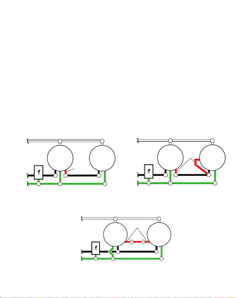
6. Alambrado incorrecto,si ésta es una nueva insta-
lación.
1. Encienda el interruptor de luz.
2. Revise la lámpara y cámbiela si está quemada.
3. Cambie el fusible encienda el disyuntor.
4. Revíselo después del anochecer.
5. Apunte de nuevo el detector para cubrir las áreas deseadas.
6. Verique que el cableado esté correcto.
Las luces se prenden durante
el día. 1. El control de luz puede estar instalado en un lugar
relativamente obscuro.
2. El control de luz está en fase de Prueba.
1. Elaparato estáfuncionandonormalmentebajoestas condiciones.
2. Fije el interruptor de control a 1, 5 o 10 minutos.
Las luces se prenden sin
ninguna razón aparente. 1. El control de luz puede estar detectando animales
pequeños o el trásito de automóviles.
2. La Sensibilidad es demasiado alta.
1. Reposicione el detector. Reduzca la sensibilidad.
2. Reduzca la sensibilidad.
Las luces se quedan prendidas
continuamente. 1. El sensor puede detectar fuentes de calor, como
ductos de calefacción y de aire acondicionado, o
supercies resplandecientes que reejan la luz.
2. El control de luz está en fase Manual.
3. La Sensibilidad es demasiado alta.
1. Reposicione el detector. Reduzca la sensibilidad.
2. Cámbiela a Auto.
3. Reduzca la sensibilidad.
Laluce seprendenyseapagan. 1. El control de luz está en fase de Prueba y calen-
tándose.
2. El calor que se reeja de otros objetos pueden estar
afectando al detector.
1. El prenderse y apagarse es normal bajo estas condiciones.
2. Reposicione el detector. Reduzca la sensibilidad.
Cambios estacionales de temperatura - Cuanto más cerca esté la temperatura ambiental al calor del cuerpo de una persona, el detector parecerá menos
sensible. Cuanto mayor sea la diferencia de temperatura, el detector parecerá más sensible. El control SENS puede necesitar ser recalibrado hacia MIN o
MAX a medida que la temperatura exterior cambia debido a las diferentes estaciones del año.Esta es una parte normal del funcionamiento del detector de luz.
CUIDADO Y MANTENIMIENTO
• Para prolongar la apariencia original, limpie solo con agua clara y un paño suave y húmedo.
• No utilice pinturas, disolventes u otros productos químicos en esta lámpara. Pueden causar un deterioro prematuro
del acabado. Esto no es un defecto en el acabado y no estará cubierto por la garantía.
• No lo rocíe con una manguera o una lavadora a presión.

18 207738-03
SERVICIO TÉCNICO
Favor de llamar al 1-800-858-8501 (sólo para hablar en inglés) para pedir ayuda antes de
devolver el producto a la tienda.
Si tiene algún problema, siga esta guía. Usted puede también visitar nuestro sitio Web: www.hzsupport.com. Si el
problema continúa, llame al 1-800-858-8501 (sólo para hablar en inglés), de 8:00 AM a 5:00 PM CST (L-V). Usted
puede también escribir a:
HeathCo LLC
P.O. Box 90045
Bowling Green, KY 42102-9045
ATTN: Technical Service (Servicio Técnico)
* Si se llama al Servicio Técnico, por favor tener lista la siguiente información: Número de Modelo, Fecha de compra y
Lugar de compra.
No hay piezas de servicio disponibles para este producto.
Por favor guarde su recibo de venta fechado; se lo requiere para cualquier solicitud de garantía.
GARANTÍA LIMITADA A 3 AÑOS
Esta es una “Garantía Limitada”que le da a Ud. derechos legales especícos. Usted puede también tener otros derechos que varían
de estado a estado o de provincia a provincia.
Por un período de 3 años a partir de la fecha de compra, cualquier mal funcionamiento causado por piezas defectuosas o por mano
de obra será reparado o reemplazado sin cargo alguno, a criterio exclusivo de HeathCo LLC.
No cubierto - Servicio de reparación,ajuste y calibración debido al mal uso, abuso o negligencia, bombillas, baterías, u otras partes
fungibles no están cubiertas por esta garantía. Cualquier daño en el aparato de luz como resultado de usar productos químicos o
lavadora a presión no están cubiertos por esta garantía. Los Servicios no autorizados o modicaciones del producto o de cualquier
componente que se provee invalidarán esta garantía en su totalidad.Esta garantía no incluye reembolso por inconveniencia,insta-
lación,tiempo de instalación, perdida de uso, servicio no autorizado, o costos de transporte de retorno.HeathCo LLC se reserva el
derecho de descontinuar productos y de cambiar especicaciones a cualquier momento sin incurrir en ninguna obligación de tener
que incorporar nuevas características en los productos vendidos con anterioridad.
Exclusiones de garantía de los acabados – Los acabados de los aparatos instalados al aire libre están sujetos a cambios debido a su
exposición prolongada a la luz solar, a los contaminantes y a otras condiciones ambientales. Los acabados de metal, naturalmente,
madurarán con el tiempo,cambiando su apariencia y creando un acabado patinado. Los acabados pintados en aparatos al aire libre
pueden desteñirse en forma natural con el tiempo,dependiendo de la exposición del aparato a la intemperie. Por lo tanto, cualquier
reclamo por desteñido,decoloración o "pátina" del acabado de un accesorio al aire libre no es aplicable a la garantía antes mencionada.
Vea la sección "Cuidado y mantenimiento" en la página 17, para una limpieza adecuada del aparato.
Esta garantía cubre solamente los productos ensamblados por HeathCo LLC y no se extiende a otros equipos o componentes que
el consumidor usa junto con nuestros productos.
ESTA GARANTÍA ESTÁ EXPRESAMENTE EN LUGAR DE OTRAS GARANTÍAS, EXPRESADAS O SOBREEN-
TENDIDAS, INCLUYENDO CUALQUIER GARANTÍA, REPRESENTACIÓN O CONDICIÓN DE COMERCIA-
BILIDAD O QUE LOS PRODUCTOS SE ADAPTEN PARA CUALQUIER PROPÓSITO O USO EN PARTICULAR,
Y ESPECIFICAMENTE EN LUGAR DE TODOS LOS DAÑOS ESPECIALES, INDIRECTOS, INCIDENTALES Y
CONSECUENTES.
LA REPARACIÓN O EL REEMPLAZO DEBERÍA SER LA ÚNICA SOLUCIÓN DEL CLIENTE Y NO HABRÁ
RESPONSABILIDAD POR PARTE DE HEATHCO LLC POR CUALQUIER DAÑO ESPECIAL, INDIRECTO, IN-
CIDENTAL O CONSECUENTE, INCLUIDOS PERO NO LIMITADOS A CUALQUIER PÉRDIDA DE NEGOCIO
O GANACIAS SEAN O NO PREVISIBLES. Algunos estados o provincias no permiten la exclusión o limitación de daños
incidentales o consecuentes, de modo que la limitación o exclusión arriba indicada puede que no se aplique a Ud.
Por favor guarde su recibo de venta fechado; se lo requiere para cualquier solicitud de garantía.

INSTRUCTIONS D’INSTALLATION ET
MODE D’EMPLOI
RENSEIGNEMENTS DE SÉCURITÉ...........................20
PRÉPARATION .............................................20
QUINCAILLERIE FOURNIE ..................................20
INSTALLATION DU LUMINAIRE............................. 21
BRANCHEMENT DU LUMINAIRE............................22
CÂBLAGE FACULTATIF .....................................23
MONTAGE DU LUMINAIRE .................................24
ESSAIS ET RÉGLAGES ......................................24
ENTRETIEN ET MAINTENANCE .............................26
GUIDE DE DÉPANNAGE ....................................26
FICHE TECHNIQUE......................................... 26
SERVICE TECHNIQUE ...................................... 27
GARANTIE LIMITÉE DE 3 ANS ..............................27
Luminaire décoratif à détecteur de mouvement
Des questions?
Consultez le guide de dépannage du guide ou
communiquez avec le service technique (en anglais
seulement) au 1800858-8501, de 8 h à 17 h, HNC,
du lundi au vendredi avant de retourner chez le
détaillant.
Conservez ce guide à titre de référence.
FIXEZ VOTRE REÇU DE CAISSE ICI
Le reçu est nécessaire pour toute demande sous
garantie.
Date d’achat
© 2020 HeathCo LLC 207738-03 F
Article Modèle
616281 SH-4132-MB
Luminaire décoratif à
détecteur de mouvement

20 207738-03
RENSEIGNEMENTS DE SÉCURITÉ
Veuillez lire et bien comprendre le guide avant de tenter
d’assembler, d’utiliser ou d’installer le produit.
Ce luminaire exige une alimentation de 120 volts c.a.Tout
le câblage doit être conforme au National Electrical Code
(Code canadien de l’électricité au Canada). Certains codes
électriqueslocauxexigentqu’unélectricienaccréditéinstalle
ce luminaire.
AVERTISSEMENT
• Coupez l’alimentation au niveau du disjoncteur
ou du fusible pour brancher le luminaire ou
remplacer les lampes. Placez un bout de ruban
adhésif sur le disjoncteur assurez-vous que le
courant est bien coupé au luminaire.
ATTENTION
• Ne coupez aucun l doté de capuchons de
connexion installés en usine et ne retirez pas ces
capuchons de connexion.
PRÉPARATION
Avant de commencer l’installation du produit,assurez-vous
de bien avoir toutes les pièces. Comparez les pièces avec la
liste de la quincaillerie fournie. S’il manque une pièce ou
si l’une d’elles est endommagée, ne tentez pas d’assembler
d’installer ou d’utiliser le produit.
Outilsnécessairesàl’assemblage(nonfournis):Tournevis
Phillips età lamedroite,pinces,pinces àdénuderet àcouper,
multimètre, ruban adhésif électrique, scellant d’étanchéité
à la silicone,lunettes de sécurité,gants de travail et échelle.
• Pourune installationetuneutilisationfacilesaumoyendu
modeManuel,remplacezunluminaireexistantcommandé
par interrupteur mural.
• Ne connectez pas ce luminaire à un gradateur ni à une
minuterie.
• Pour un meilleur rendement, installez le luminaire à
environ 6 pieds (1,8 m) du sol.
Durée estimative de l’installation:30 minutes
3x – Capuchons de
connexion
2x – Vis de montage
du support
A - (1x) Support de montage
B - (2x) Vis de montage du
luminaire
C - (2x) Écrou décoratif
(Cet élément est xé
à l’endos du couvercle de
la lanterne.)
QUINCAILLERIE FOURNIE
Remarque: Les illustrations peuvent être diérentes de
l’appareil acheté.
A
B
C
This manual suits for next models
1
Table of contents
Languages:
Other Secure Home Outdoor Light manuals