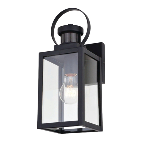
Secure Home Heath Zenith DUALBRITE SH-4266-PB User manual

© 2013 HeathCo LLC 206476-01A
INSTALLATION AND OPERATING
INSTRUCTIONS
SAFETY INFORMATION ......................................2
PREPARATION ...............................................2
HARDWARE CONTENTS......................................2
LIGHT FIXTURE INSTALLATION...............................3
WIRING THE LIGHT FIXTURE .................................4
OPTIONAL WIRING ..........................................5
MOUNTING THE LIGHT FIXTURE .............................6
TESTING AND ADJUSTMENTS................................6
FINAL SETUP ................................................6
OPERATION .................................................7
MANUAL MODE .............................................7
CARE AND MAINTENANCE...................................7
TROUBLESHOOTING GUIDE..................................8
SPECIFICATIONS.............................................8
TECHNICAL SERVICE.........................................9
THREE YEAR LIMITED WARRANTY ............................9
DUALBRITE®Motion Sensing
Coach Light with BulbSaver*
Technology
Motion Decorative Light
Questions?
Please refer to the troubleshootingguide in this manual
or call our technical service department (English speak-
ing only) at 1-800-858-8501, 8:00 a.m. - 5:00 p.m., CST,
Monday - Friday before returning to your retailer.
Keep this manual for future reference.
ATTACH YOUR RECEIPT HERE
Receipt is required for all warranty requests.
Purchase Date
* BulbSaver - Light comes on dim and gradually increases to
full brightness. When the light turns o it will gradually dim to
half-bright, pause, and then will continue dimming until the
light turns o.
For a description of the DualBrite® technology, see page 6.
Item Model
12043 SH-4266-PB
21746 SH-4266-SA
482286 SH-4266-BK

2206476-01
SAFETY INFORMATION
Please read and understand this entire manual before at-
tempting to assemble, operate, or install the product.
is light xture requires 120-volts AC.All wiring must be
in accordance with the National Electrical Code (Canadian
Electrical Code in Canada). Some local electrical codes
require installation by a qualied electrician.
WARNING
t 5VSOQPXFSPòBUDJSDVJUCSFBLFSPSGVTFXIFO
XJSJOHöYUVSFPSSFQMBDJOHCVMCT1MBDFUBQFPWFS
DJSDVJUCSFBLFSTXJUDIBOEWFSJGZQPXFSJTPòBU
UIFöYUVSF
CAUTION
t %POPUDVUBOZXJSFTUIBUIBWFGBDUPSZJOTUBMMFE
XJSFDPOOFDUPSTPSSFNPWFUIFXJSFDPOOFDUPST
PREPARATION
Beforebeginning installation of product,make sure allparts
are present. Compare parts with hardware contents list. If
any part is missing or damaged,do not attempt to assemble,
install, or operate the product.
ToolsRequired forAssembly (notincluded): Phillips and
athead screwdrivers, pliers, wire strippers/cutters, multi-
meter, electrical tape, silicone sealant, safety glasses, work
gloves, and ladder
R5 ),5-35#(-.&&.#)(5(5.)5)*,.5."5&#!".5/-#(!5(/&5
mode, replace an existing light xture operated by a wall
switch.
R5 )5().5)((.5.)5#'',-5),5.#',-85
R5 ),5-.5*, ),'(65')/(.5ŀ2./,5)/.5l5 .5Bg8n5'C5
above the ground.
Estimated Installation Time: 30 minutes
3x – Wire Connectors
2x – Mounting
Bracket Screw
1x – Mounting Bracket
2x – Fixture Mounting Screws
2x – Decorative Nut
(This assembly is attached
to the rear of the lantern
canopy.)
HARDWARE CONTENTS
Note: Illustrations may vary from actual unit.

3206476-01
Wire Path
Ground Screw
Mounting
Plate
LIGHT FIXTURE INSTALLATION
),5-.5*, ),'(65')/(.5."5ŀ2./,5)/.5l5 .5Bg8n'C5
above the ground.
1. Remove two decorative nuts.
2. Remove mounting plate.
3. Tighten mounting screws nger tight.
4. Set sensitivity control on back of xture to MIN
position.
5. Attach mounting plate to junction box.
Decorative Nut
Mounting Screw
Bracket
Mounting
Screws Mounting Plate
Junction
Box
Note: We recommend having an assistant help hold the
lantern assembly during the wiring process.
is xture comes with a universal mounting bracket. It is
pre-assembled on the xture to t the majority of junction
box applications.
If the slots on the mounting plate do not line up with the
junction box screw holes, follow these steps:
1. Removethexturemountingscrewsfromthemounting
plate. Note:5)5().5,')05."5!,)/(5-,18
2. Attach ground wire “pigtail” to ground screw on
mounting plate (See
Recommended Grounding Method
for additional information).
i85 &#*5."5')/(.#(!5*&.5)0,8
4. Rotate the mounting plate so the wire path is on the
upper right.Note: e wire path on the mounting plate
must be located as shown below to allow the wires on
the back of the xture to pass through.
5. Reinstall the xture mounting screws and attach the
mounting plate to the junction box as shown.
Wire Path
As Shipped Flipped and
Rotated
Wire Path
Fixture Screws
Ground Screw
MAX
SENS
MIN

4206476-01
#MBDL to CMBDL
White to white
Recommended Grounding Method
Use a green ground “pigtail” (not provided) and twist
one end together with the bare xture wire and the box
ground wire. Secure with a wire connector. Secure the
).",5(5) 5."5^*#!.#&_51#."5."55-,15)(5."5
mounting plate.
WIRING THE LIGHT FIXTURE
CAUTION: DO NOT connect the RED wire
VOMFTTZPVXBOUUPDPOUSPMPUIFSMJHIUTGSPNUIF
motion sensor (see Optional Wiring
Note: All wiring must be run in accordance with the Na-
tional Electrical Code through conduit or another accept-
able means. Contact a qualied electrician if there is any
question as to the suitability of the system.
8"3/*/( 5VSO QPXFS Pò BU DJSDVJU CSFBLFS
PSGVTF
Connect the xture wires to the wires in the junction box.
Twist the wires together and secure with wire connectors.
If you have metal junction box,you may not need the green
“pigtail”. If you are unsure about the grounding method,
consult your local building code.
One Motion Light
Two Motion Lights
Black
White
Green
or Bare
Copper
Green
or Bare
Copper
Light
Fixture
Black
White
Light
Fixture
Light
Fixture

5206476-01
Green
or Bare
Copper
Green
or Bare
Copper
Green
or Bare
Copper
OPTIONAL WIRING
Ļ#-5ŀ2./,5#-5*,)0#51#."55-(-),5,.5 ),5ilf5..-85#(5."5ŀ2./,5#-5)(&35,.5gff5..-65hlf5..-5) 5-
ditional lighting may be controlled by this sensor.
When determining what a xture is rated for, do not simply look at the rating on the light bulb in the xture. Look at
the marking which species the maximum bulb wattage for which the xture is suitable.
(53)/5"05-&.5."5ŀ2./,-5.)55)((.5(5.,'#(5."#,5'2#'/'5,.#(!-655."-5,.#(!-5/*85),5
instance,if you have 3 xtures rated 100 Watts, 150 Watts,and 75 Watts respectively,you have a total load of 325 Watts.
Wiring Diagram 1 – When wiring to control a standard light xture: Strip the motion sensor’s red wire and connect to
the standard light’s black51#,85)((.5&&51"#.51#,-5.)!.",85).&5ŀ2./,5,.#(!-5'/-.5().525ilf5..-5Bi8f5C8
Wiring Diagram 2 –5"(51#,#(!5.)5)(.,)&5().",5').#)(5-(-#(!5&#!".5ŀ2./,5B-.,5I5&0C95.,#*5."5red wire in
both light xtures. Connect the red wire of the controlling (master) xture to the red and black wires of the controlled
B-&0C5ŀ2./,85)((.5&&51"#.51#,-5.)!.",85).&5ŀ2./,5,.#(!-5'/-.5().525ilf5..-5Bi8f5C8
Wiring Diagram 3 – "(51#,#(!5-)5#.",5').#)(5&#!".5./,(-5)(5."5)."5').#)(5&#!".-5B-.,5I5-.,C95.,#*5."5
red wire in both light xtures. Connect the red wire of one xture to the red wire of the second xture. Note: In most
installations, an additional wire (same gauge as existing house wire) will have to be installed in the house to connect the
two xtures as master / master. Connect all white wires together and all black wires together. Total xture ratings must
().525ilf5..-5Bi8f5C8
Black
White
Light
Fixture
Light
Fixture
(Standard) Master Slave
Black
White
Light
Fixture
Light
Fixture
Red
Red
Wiring Diagram 1 Wiring Diagram 2
Wiring Diagram 3
Master Master
Black
White
Red
Light
Fixture Light
Fixture

6206476-01
TEST 1 5 10
MINUTE
OFF 3 6 DUSK TO
HOUR DAWN
Junction
Box
MOUNTING THE LIGHT FIXTURE
g85 %5-/,51#,5)((.),-5(5 1#,-5,5#(-#5."5
junction box.
2. Slide the xture assembly onto the mounting screws.
Tighten decorative nuts removed in step 1 of
Light
Fixture Installation
section securely against xture base.
Mounting Screw
Decorative Nut
3. Install one medium base light bulb (100 Watt
maximum).
TESTING AND ADJUSTMENTS
*OJUJBM4FUVQ
e TEST mode overrides the photocell (daylight shuto
feature) and allows the light xture to be tested day or night
1"(5."575-1#."5#-5#(5."55*)-#.#)(85Ļ5
light will stay on for 5 seconds after all motion has stopped.
Rotating Sensor Head to Change Coverage Area
1
5
0
°
1
5
0
°
l85
)05."5-(-),5"5& .5),5,#!".5.)5"(!5."5)0,!5
area. Note: Grasp the sensor only as shown and turn
the entire sensor. Any other method may damage
UIFTFOTPS%POPUGPSDFJUQBTUUIFTUPQT
g85 /,(5."5/&,#.5)(.,)&5.)58
h85 .5."575)(.,)&5.)58
3. Turn on the circuit breaker or fuse and the light switch.
4. Allow the sensor to completely warm up (90 seconds)
before beginning the setup process.
5. Perform a walk test. Walk in an arc across the front of
the sensor.
Sensor Controls
FINAL SETUP
0QFSBUJOH.PEFT
R5 Motion Sensor (AUTO) – is light xture is designed
to automatically turn on when the sensor detects a tem-
perature dierence moving across the front of the motion
sensor. e light will turn o automatically after a set
')/(.5) 5.#'85Ļ575)(.,)&5-")/&55-.5
to 1, 5, or 10 minute setting and the wall switch should
be left in the ON position at all times.
R5 Optional DualBrite® Control – is optional feature
allows the light xture to turn on at a lower light level
after dusk (sunset) for theamountoftimeselected.When

7206476-01
30 ft. (9.1 m)
6 ft. (1.8 m)
150°
Maximum Range Maximum
Coverage Angle
(Top View)
Note: When rst turned on wait about 1 1/2minutes for
the circuitry to calibrate.
L5,-.-5.)5/.)5)5.51(8
OPERATION
Caulking Around Fixture Base
Mode: On-Time 8PSLT Day Night
Test 5 Seconds x x
Auto 1, 5, or 10 #(/.- x
Accent i65l5)/,65)51( x
Manual )51(L x
Turn Switch OFF for
1 to 2 seconds Turn Switch
Back ON
MANUAL MODE
5')5)(&351),%-5 .,5,%5(5 ),5)(&35)(5
(#!".5.55.#'855')51#&&5(5.)55.)!!&5
on each night as needed. Note: If power to the light xture
is o for more than 5 seconds,allow the electronic circuitry
in the sensor to calibrate (90 seconds) prior to switching
to manual mode.
g85 )5./,(5)(55')65-1#."5."5&#!".5)Ŀ5.5
the wall switch for 1 to 2 seconds and then back on.
2. To return to AUTO mode, switch the light o at the
wall switch for 1 to 2 seconds and then back on.
Note: e sensor will also reset to AUTO mode at
sunrise.
CARE AND MAINTENANCE
R5 )5*,)&)(!5."5),#!#(&5**,(65&(51#."5&,51.,5
and a soft damp cloth only.
R5 )5().5/-5*#(.-65-)&0(.-65),5).",5"'#&-5)(5."#-5
light xture.ey could cause a premature deterioration
of the nish.is is not a defect in the nish and will not
be covered by the warranty.
R5 )5().5-*,351#."5")-5),5*)1,51-",8
motion is detected,the lights will turn on full bright.is
./,5(55./,(55(5."5').#)(5-(-),51#&&5
continue to work in AUTO mode.
R5 Manual Mode – is light can be activated to stay on full
bright after dusk (sunset) for only one night at a time. It
automatically resets to motion sensing at dawn (sunrise).
(/&5')5'/-.55,7.#0.5"5(#!".8
1.
Adjust the sensitivity (SENS) to increase or decrease
the range as needed. Too much sensitivity may cause
false triggering due to heat sources in the coverage area
(see
Testing and Adjustments or Troubleshooting
section).
h85 .5."5')/(.5) 5753)/51(.5."5&#!".5.)5
stay on after motion is detected (1, 5, or 10 minutes).
3. Set the šōŘŞŕŠőX5-1#."5.)5)Ŀ65i5")/,-65l5")/,-65
or dusk-to-dawn.
4. Caulkaround xturebase withsilicone weatherseal-
ant after all Testing and Adjustments are complete.

8206476-01
SPECIFICATIONS
Range ................................................................Up to 30 ft. (9.1 m) [varies with surrounding temperature]
Sensing Angle....................................................Up to 150°
Sensor Aiming Adjustment Angle ....................90°
Electrical Load ..................................................*5.)5gff5..52#'/'5((-(.
Bulb Type ..........................................................#/'5-653*5^_65gff5..52#'/'
Sensor Capacity.................................................*5.)5ilf5..5Bi8f5C52#'/'5/(!-.(
Power Requirements..........................................ghf565lf54
*,.#(!5)- ..............................................6565(55
ON-Timer.........................................................1, 5, 10 minutes
šōŘŞŕŠőX Timer..........................................Ŀ65i65l5")/,-65/-%7.)51(
Test Timer.........................................................5 Seconds
(/&5)5#',........................................./-%7.)71(
SYMPTOM POSSIBLE CAUSE SOLUTION
Lights will not
come on. 1. Light switch is turned o.
2. Light bulb is loose or burned out.
i85 /-5#-5&)1(5),5#,/#.5,%,5#-5./,(5)Ŀ8
j85 3&#!".5./,(7)Ŀ5#-5#(5Ŀ.8
5. Sensor not detecting movement.
l85 (),,.5#,/#.51#,#(!65# 5."#-5#-55(15#(-.&&.#)(8
1. Turn light switch on.
2. Check bulb and replace if burned out.
3. Replace fuse or turn circuit breaker on.
4. Recheck after dark.
5. Re-aim the sensor to cover desired area.
l85 ,# 351#,#(!5#-5),,.8
Lights come on in
daylight. 1. Light control may be installed in a relatively dark location.
2. Light control is in TEST. 1. e xture is operating normally under these conditions.
2. Set control switch to 1, 5, or 10 minutes.
Lights come on for
no apparent reason. 1. Light control may be sensing small animals or automobile
trac.
2. Sensitivity is set too high.
1. Re-aim sensor. Reduce sensitivity.
2. Reduce sensitivity.
Lights stay on
continuously. 1. e sensor may be picking up a heat source like an air vent,
dryer vent, or brightly painted, heat-reective surface.
h85 #!".5)(.,)&5#-5#(5(/&5)8
3. Light control is in šōŘŞŕŠőX5')8
4. Sensitivity is set too high.
1. Re-aim sensor. Reduce sensitivity.
2. Switch to Auto.
3. Slide šōŘŞŕŠőX5-1#."5.)55*)-#.#)(8
4. Reduce sensitivity.
Lights ash on
and o. 1. Light control is in the TEST mode and warming up.
h85 .5#(!5,ł.5 ,)'5).",5)$.-5'355Ŀ.#(!5."5
sensor.
g85 &-"#(!5#-5(),'&5/(,5."-5)(#.#)(-8
2. Re-aim sensor. Reduce sensitivity.
Seasonal Temperature Changes – e closer the surrounding temperature is to a person’s body heat, the less sensitive the sensor will appear. e greater
."5.'*,./,5#Ŀ,(65."5'),5-(-#.#05."5-(-),51#&&5**,85Ļ55)(.,)&5'#!".5(5.)55,$/-.5.)1,55),55-5."5)/.-#5
temperature changes for the dierent seasons.is is a normal part of the light sensor’s operation.
TROUBLESHOOTING GUIDE

9206476-01
TECHNICAL SERVICE
1MFBTFDBMM&OHMJTITQFBLJOHPOMZGPSBTTJTUBODF
CFGPSFSFUVSOJOHQSPEVDUUPTUPSF
If you experience a problem, follow this guide. You may also want to visit our Web site at: www.hzsupport.com. If the
problem persists, call* for assistance at 1-800-858-85015B(!&#-"5-*%#(!5)(&3C65n9ff55.)5k9ff555B7C85
You may also write* to:
.")5
P.O. Box 90045
Bowling Green, KY 42102-9045
ATTN: Technical Service
L5 5)(..#(!5"(#&5,0#65*&-5"05."5 )&&)1#(!5#( ),'.#)(50#&&95)&5/',65.5) 5/,"-65
and Place of Purchase.
/P4FSWJDF1BSUT"WBJMBCMFGPSUIJT1SPEVDU
Please keep your dated sales receipt, it is required for all warranty requests.
THREE YEAR LIMITED WARRANTY
is is a “Limited Warranty” which gives you specic legal rights. You may also have other rights which vary from state to state
or province to province.
),55*,#)5) 5.",53,-5 ,)'5."5.5) 5*/,"-65(35'& /(.#)(5/-535 .),35 .#05*,.-5),51),%'(-"#*51#&&55
corrected at no charge to you.
Not Covered - Repair service, adjustment and calibration due to misuse, abuse or negligence, light bulbs, batteries, and other
2*(&5#.'-5,5().5)0,535."#-51,,(.385(/."),#45-,0#5),5')#ŀ.#)(5) 5."5*,)/.5),5) 5(35 /,(#-"5)'-
ponent will void this warranty in its entirety. is warranty does not include reimbursement for inconvenience, installation, setup
.#'65&)--5) 5/-65/(/."),#45-,0#65),5,./,(5-"#**#(!5",!-8
Finish Warranty Exclusions -5#(#-"-5 ),5ŀ2./,-5#(-.&&5)/.)),-5,5-/$.5.)5"(!5/5.)5*,)&)(!52*)-/,5.)5-/(&#!".65
*)&&/.(.-65(5).",5(0#,)('(.&5)(#.#)(-85.&5ŀ(#-"-51#&&5(./,&&35'./,5)0,5.#'65"(!#(!5#(5**,(5(5,.#(!5
a living nish.Painted nishes on outdoor xtures may naturally fade over time,depending on the xture’s exposure to the outdoor
elements.us, any claim for fading, discoloration, or “patina”of a nish on an outdoor xture is not applicable to the above war-
,(.3855^,5(5#(.((_65page 7, for proper cleaning of the xture.
Ļ#-51,,(.35)0,-5)(&35.")55--'&5*,)/.-5(5#-5().52.(5.)5).",5+/#*'(.5(5)'*)((.-5.".55/-.)',5
uses in conjunction with our products.
5555555556555655
5655555555555
5555555655555556565
65558
5 5 5 5 55 5 5 55 5 55 5
55 5 55 55 55 5565 65 65 5
565555555555565
55585)'5-..-5),5*,)0#(-5)5().5&&)15."52&/-#)(5),5&#'#..#)(5) 5#(#(.&5),5
consequential damages, so the above limitation or exclusion may not apply to you.
Please keep your dated sales receipt, it is required for all warranty requests.
.")55,-,0-5."5,#!".5.)5#-)(.#(/5*,)/.-5(5.)5"(!5-*#ŀ.#)(-5.5(35.#'51#.")/.5#(/,,#(!5(35
obligation to incorporate new features in products previously sold.

10 206476-01
INSTRUCCIONES PARA SU INSTALACIÓN
Y FUNCIONAMIENTO
INFORMACIÓN SOBRE LA SEGURIDAD .....................11
PREPARACIÓN.............................................11
FERRETERÍA OFRECIDA .................................... 11
INSTALACIÓN DEL APARATO DE LUZ ....................... 12
CABLEADO DEL APARATO DE LUZ ......................... 13
CONEXIÓN ALTERNA ...................................... 14
MONTAJE DEL APARATO DE LUZ...........................15
PRUEBAS Y AJUSTES....................................... 15
CONFIGURACIÓN FINAL ................................... 15
OPERACIÓN ...............................................16
MODALIDAD MANUAL ....................................16
CUIDADO Y MANTENIMIENTO ............................. 16
GUÍA DE INVESTIGACIÓN DE AVERÍAS .....................17
ESPECIFICACIONES ........................................17
SERVICIO TÉCNICO ........................................ 18
GARANTÍA LIMITADA A 3 AÑOS............................ 18
-V[UJQPDPDIFEFUFDUPSBEF
movimiento DualBrite® con
tecnología BulbSaver*
Luz decorativa detectora de movimiento
* Bulb Saver - La luz se enciende tenue y aumenta gradualmen-
te a su brillo completo. Cuando se apaga, la luz irá gradual-
mente de tenue a medio-brillante, hará una pausa, y luego
continuará atenuándose hasta que la luz se apague.
Para una descripción de la tecnología DualBrite ®, vea la página 15.
Artículo Modelo
12043 SH-4266-PB
21746 SH-4266-SA
482286 SH-4266-BK
¿Preguntas?
Por favor, consulte la guía de solución de
problemas en este manual o llame a nuestro de-
partamento de servicio técnico (solo para Inglés) al
1-800-858-8501, de 8:00 am - 5:00 pm, hora central,
de lunes a viernes antes de volverlo a la tienda.
Guarde este manual para referencia en el futuro.
ADJUNTE SU RECIBO AQUÍ
Se requiere recibo para todas las solicitudes de
garantía.
Fecha de compra
© 2013 HeathCo LLC 206476-01 S

11206476-01
INFORMACIÓN SOBRE LA
SEGURIDAD
Por favor lea y comprenda todo el manual antes de intentar
ensamblar, operar o instalar el producto.
Esta lámpara requiere de 120 voltios CA.Todo el cableado
debe ser de acuerdo con el Código Nacional de Electricidad
(CódigoEléctricoCanadienseenCanadá).Algunoscódigos
eléctricos locales requieren que la instalación sea hecha por
un electricista calicado.
ADVERTENCIA
t %FTDPOFDUFMBBMJNFOUBDJØOFOFMEJTZVOUPSP
GVTJCMFDVBOEPIBHBFMDBCMFBEPEFMBMÈNQBSB
PDBNCJFMBTCPNCJMMBT1POHBDJOUBBEIFTJWB
TPCSFFMJOUFSSVQUPSEFMEJTZVOUPSZWFSJöRVFRVF
MBFMFDUSJDJEBEFTUÏBQBHBEBFOMBMÈNQBSB
PRECAUCIÓN
t /PDPSUFOJOHÞODBCMFRVFUFOHBDPOFDUPSFT
EFDBCMFTJOTUBMBEPTFOGÈCSJDBOJSFUJSFMPT
DPOFDUPSFT
PREPARACIÓN
(.-55)'(4,5&5#(-.&#ĉ(65-!Ě,-55+/5.#(5
.)-5&-5*#4-85)'*,5&-5*#4-5)(5&5&#-.55 ,,.,ù5
) ,#85#5&!/(5*#45 &.5 )5-.á5Ą65()5#(.(.5
(-'&,65#(-.&,5)5/.#,5&5*,)/.)8
Herramientas necesarias para el montaje (no incluidas):
-.),(#&&),-5"#&&#*-535545*&(65*#(4-65-*-
,),-5I5),.),-55&',65'/&.ù'.,)65#(.5#-&(.65
sellador de silicona, gafas de seguridad, guantes de trabajo
y escalera.
R5 ,5/(5#(-.&#ĉ(5 á#&535*,5)*,,5&5&/45/.#()5
&5')(/&65'#5&5*,.)55&/452#-.(.5
que funciona con un interruptor de pared.
R5 )5&)5)(.55.(/),-5)5.'*),#4),-8
R5 ,5/(5'$),5 /(#)('#(.)65')(.5&5/(#5,55
l5*#-5Bg6n5'C5*),5(#'5&5-/&)8
Tiempo estimado de instalación: 30 minutos
3x – Conectores de alambre
2x – Tornillo del
soporte de montaje
FERRETERÍA OFRECIDA
Nota: Las ilustraciones pueden ser diferentes de la unidad
comprada.
1x – Soporte de montaje
2x – Tornillos de montaje
del aparato
2x – Tuerca decorativa
(Este conjunto está sujeto
a la parte trasera del farol)

12 206476-01
Paso del alambre Paso del alambre
Como se enviaron Placa volteada
y girada
Paso del alambre
Placa de
montaje
Tuerca decorativa
Tornillo de
montaje
Tornillo de
montaje del
soporte
Placa de montaje
La caja de
empalme
INSTALACIÓN DEL APARATO DE LUZ
Para un mejor funcionamiento, instale el aparato a casi
g8n5'5&5-/&)8
g85 /#.5)-5./,-5),.#0-8
h85 /#.5&5*&55')(.$8
3. Ajuste lo más que pueda los tornillos para montaje con
sus dedos.
4. Fije el control de sensibilidad en la parte posterior
del aparato a la posición MIN.
5. Atornille la placa de montaje a la caja de empalme.
Nota: Recomendamos tener un asistente que ayude a sos-
tener el conjunto del farol durante el proceso de cableado.
Este aparato viene con un soporte de montaje universal.
Está pre-ensamblado en el aparato para acomodarse a la
'3),ù55&-5*&##)(-55$-55'*&'8
Sin embargo, si las ranuras de la placa de montaje no se
alineanconlosagujerosdeltornillodelacajadeempalme:
g85 /#.55&5*&55')(.$5&)-5.),(#&&)-55')(.$5
del aparato. Nota: No quite el tornillo de a tierra.
h85 #$5&5&5^ł2#&_5&5.),(#&&)555.#,,55&5*&5
de montaje (Vea
Método recomendado de conexión a tierra
para más información).
3. Voltee la placa de montaje
4. Voltee la placa de montaje de modo que el agujero de
pasodelalambreesté en la partederechasuperior.Nota:
El agujero de paso del alambre en la placa de montaje
debe estar ubicado como se muestra abajo para que los
alambres de la parte de atrás del aparato puedan pasar.
5. Reinstale los tornillos de montaje del aparato y je la
placa de montaje a la caja de empalme como se muestra.
MAX
SENS
MIN
Tornillos del tierra Tornillos del aparato
Tornillos del tierra

13206476-01
"%7&35&/$*"%FTDPOFDUFMBBMJNFOUBDJØOFO
FMEJTZVOUPSPFOFMGVTJCMF
Negro a negro
.ÏUPEPSFDPNFOEBEPEFDPOFYJØOBUJFSSB
Use un “cable exible” verde de tierra (no provisto) y
./,45/(52.,')5)(5&5&5-(/)5&5*,.)535)(5
&5&555.#,,55&5$85-!Ě,&)-5)(5/(5)(.),5
de cables.Asegure el otro extremo del“cable exible”con
el tornillo de a tierra de la placa de montaje.
$6*%"%0/0DPOFDUFFMDBCMF30+0FYDFQUP
RVFEFTFFDPOUSPMBSPUSBTMVDFTEFTEFFMEFUFDUPSEF
movimiento (Vea Conexión Alterna
Nota:5))5&5&)55,,-55/,)5)(5&5
ĉ#!)5 &ï.,#)5 #)(&5 /-()5 ./,ù5 )5 &!Ě(5 ).,)5
medio aceptable. Póngase en contacto con un electricista
calicado si tiene alguna pregunta referente a la aptitud
del sistema.
Conecte los alambres del aparato a los alambres de la caja
5'*&'85/,45$/(.)-5&)-5&',-535-!Ě,&)-5)(5
conectores de alambre.
Si tiene una caja de empalme de metal,no necesita el “cable
exible”. Si no está seguro del método de conexión a tierra,
consulte con el código local de construcción.
Luz de un movimiento
Luz de dos movimientos
Negro
Negro
Blanco
Blanco
Verde o
desnudo
Verde o
desnudo
Artefacto
de luz
Artefacto
de luz Artefacto
de luz
Blanco a blanco
CABLEADO DEL APARATO DE LUZ

14 206476-01
(Estándar) Maestra Esclava
Rojo
Rojo
Esquema eléctrico 1 Esquema eléctrico 2
Esquema eléctrico 3
Maestra Maestra
Rojo
CONEXIÓN ALTERNA
-.5*,.)50#(5)(5/(5..),5)(5/(5*).(#55ilf5.#)-85/-.)5+/5-.5*,.)5.#(5-ĉ&)5/(5*).(#55
gff50.#)-65hlf50.#)-55&/45##)(&5*/(5-,5)(.,)&)-5*),5-.5..),8
/()5-5.,'#(,5&5&-#ŀ#ĉ(55/(5*,.)5()505.(5-ĉ&)5&5*).(#55&5&á'*,85#,5&5#(##ĉ(5+/5
especique el voltaje máximo de la lámpara que el aparato puede aceptar.
(5045+/5"5-)!#)5&)-5*,.)-5+/5-5)(.,á(535"5.,'#()5-/-5'á2#'-5*).(#-65-Ě'&-85),5$'*&)65
si tiene 3 aparatos de 100 , 150 y 75 Vatios respectivamente, usted tendrá un total de 325 Vatios.
Esquema eléctrico 1 – Cuando prepare una conexión para controlar un aparato de luz estándar: Pele el alambre rojo
del detector de movimiento y conéctelo al alambre negro55&5&/45-.á(,85)(.5.))-5&)-5&',-5&()-855
*#5.).&5()552,5&)-5ilf5.#)-5Bi8f5C8
Esquema eléctrico 2 – Cuando prepare una conexión para controlar otro aparato de luz detector de movimiento:
Pele el alambre rojo5(5')-5*,.)-55&/485)(.5&5&',5rojo del aparato controlador (maestro) a los alambres
rojo y negro del aparato controlado (esclavo). Conecte todos los alambres blancos. La capacidad total no debe exceder
&)-5ilf5.#)-5Bi8f5C8
Esquema eléctrico 3 – Cuando haga el cableado para que cualquier luz de movimiento prenda las dos luces que de-
tectan movimiento (Maestro / Maestro): Pele el conductor rojo55')-5*,.)-55&/485)(.5&5)(/.),5rojo
de un aparato al conductor rojo del otro aparato. Nota:5(5&5'3),ù55&-5#(-.&#)(-5-5,á5#(-.&,5/(5)(/.),5
adicional (del mismo calibre que el conductor de la casa) dentro de la casa para conectar los dos aparatos como maestro /
maestro. Conecte entre si todos los alambres blancos y todos los alambres negros.La potencia nominal total del aparato
()55-,5'á-55ilf50.#)-5Bi8f5'*C8
Negro Negro
Negro
Blanco Blanco
Blanco
Verde o
desnudo
Verde o
desnudo
Verde o
desnudo
Artefacto
de luz Artefacto
de luz Artefacto
de luz Artefacto
de luz
Artefacto
de luz
Artefacto
de luz

15206476-01
TEST 1 5 10
MINUTE
OFF 3 6 DUSK TO
HOUR DAWN
MONTAJE DEL APARATO DE LUZ
g85 -!Ě,-5+/5&)-5)(.),-55&',535&)-5&',-5
estén dentro de la caja de empalme.
h85 -&5)($/(.)5&5*,.)5-),5&)-5.),(#&&)-55
montaje. Apriete las tuercas decorativas quitadas en
el paso 1 de la sección
Instalación del Aparato de Luz
rmemente en la base del aparato.
3. Instale una base media para bombilla (100 vatios
máximo).
PRUEBAS Y AJUSTES
$POöHVSBDJØOJOJDJBM
LamodalidadTESTanulalafotocélula(funcióndeapagado
/,(.5&5ùC535*,'#.5+/5&5*,.)55&/45-5*,))5
/,(.5&5ù5)5&5()"5/()5&5#(.,,/*.),575
-5 (/(.,5 (5 &5 *)-##ĉ(585 5 &/45 *,'(,á5
encendida por 5 segundos después de que todo movimiento
se haya detenido.
1
5
0
°
1
5
0
°
l85
/05&545&5..),5"#5&5#4+/#,5)5,"5
para cambiar el área de protección. Nota: Agarre sólo
el detector, como se muestra, y gire todo el detector.
$VBMRVJFSPUSPNÏUPEPQVFEFEB×BSMP/PMPGPSDÏ
NÈTBMMÈEFMPTQVOUPTEFQBSBEB
g85 #,5&5)(.,)&5/&,#.558
h85 #$5&5)(.,)&57558
3.
(#(5&5#-3/(.),5)5 /-#&535&5#(.,,/*.),55&5&/48
j85 $5+/5&5-(-),5-5&#(.5*),5)'*&.)5Bof5-!/()-C5
(.-55)'(4,5&5*,)-)55#(-.&#ĉ(8
k85 !5/(5*,/55*-)85'#(5(5,)5*),5&5*,.5
delantera del detector.
Controles del detector
CONFIGURACIÓN FINAL
.PEBMJEBEFTEFPQFSBDJØO
R5 Detector de movimiento (AUTO) – Esta lámpara está
#-Ą5*,5*,(,-5/.)'á.#'(.5/()5&5-(-),5
detecta una diferencia de temperatura que se mueve por
&5 ,(.5&5..),55')0#'#(.)855&/45-5*!,á5
automáticamente después de un determinado tiempo.
&5)(.,)&575-55ŀ$,55g65k5)5gf5'#(/.)-5
y al interruptor de pared se lo debe dejar siempre en la
posición ON.
R5 Control opcional DualBrite® – Esta función opcional
*,'#.5+/5&5&á'*,5-5(#(55/(5(#0&55&/45$5
después del atardecer (puesta del sol) por la cantidad de
tiempo seleccionada. Cuando se detecta movimiento,las
Tuerca decorativa
La caja de
empalme
Tornillo de montaje
Giro de la cabeza del detector para cambiar el área de
cobertura

16 206476-01
Nota:5/()5(#(5*),5*,#',50465-*,5g51/2minutos
para que los circuitos se calibren.
*Se pone en Automático al amanecer.
OPERACIÓN
Modalidad: "UJFNQP Trabaja: ù Noche
Prueba 5 segundos x x
"VUPNÈUJDP 1, 5 o 10 min. x
Adorno i65l5",-65"-.5&5
amanecer x
Manual -.5&5'(,L x
Alcance Máximo Ángulo de
Cobertura Máxima
(Vista desde arriba)
30 ft. (9.1 m)
6 ft.
(1.8 m)
150°
Calafateo alrededor de la base del aparato
MODALIDAD MANUAL
La modalidad manual funciona sólo por la noche y por
-ĉ&)5/(5()"55&504855')ȫ-,5
.#055()"5-!Ě(5-5(-,#)85Nota: Si la lámpara
está apagada por más de 5 segundos, deje que el circuito
electrónico del detector se calibre (90 segundos) antes de
cambiar a la modalidad manual.
g85 ,5.#0,5&5')ȵ*!/5&5&/45
en el interruptor de pared de 1 a 2 segundos y vuelva a
prenderla.
h85 ,50)&0,55&5')ȵ*!/5&5&/45(5
el interruptor de pared de 1 a 2 segundos y vuelva a
prenderla. Nota: El detector también se restablecerá a
la modalidad AUTO al amanecer.
luces se prenderán con todo su resplandor. Esta caracte-
,ù-.#5*/5-.#0,-535&5..),55')0#'#(.)5
seguirá trabajando en la modalidad AUTO.
R5 Modalidad Manual –5-.5&/45-5*/5.#0,5*,5+/5
*,'(45)(5.))5-/5,-*&(),5-*/ï-5&5.,,5
B*/-.5&5-)&C5*),5-ĉ&)5/(5()"5*),504855,-.&5
automáticamente para detectar movimiento al amanecer
(salida del sol). La modalidad manual se debe reactivar
cada noche.
1. Regule la sensibilidad (SENS) para aumentar o dis-
'#(/#,5&5&(5-!Ě(5&)5+/5 (-#.85 '-#5
sensibilidad puede ocasionar falsas alarmas debido a
/(.-55&),5(5&54)(55),./,5B05&5-#ĉ(5
Ajustedelazona de cobertura
olasección
Análisisdeaverías
).
h85 #$5&5*,ù))55.#'*)5B7C5+/5&5&/455
quedarse prendida después de detectar movimiento (1,
5 o 10 minutos).
3. Ponga el interruptor šōŘŞŕŠő en apagado (o),
i5 "),-65 l5 "),-65 )5 /-%7.)71(5 B&5 ()",5 &5
amanecer).
4. Calafatee alrededor de la base del aparato con un
sellador de silicona contra la intemperie después de
completar todos los Pruebas y Ajustes.
Apague el interruptor
de 1 a 2 segundos Vuelva a prender
el interruptor
CUIDADO Y MANTENIMIENTO
R55,5*,)&)(!,5&5*,#(#5),#!#(&65&#'*#5-)&)5)(5!/5
&,535/(5*Ą)5-/0535"Ě')8
R55)5/.#*#(./,-65#-)&0(.-5/5).,)-5*,)/.)-5+/ù'#)-5
en esta lámpara. Pueden causar un deterioro prematuro
del acabado. Esto no es un defecto en el acabado y no
-.,á5/#,.)5*),5&5!,(.ù8
R55)5&)5,)ù5)(5/(5'(!/,5)5/(5&0),55*,-#ĉ(8

17206476-01
ESPECIFICACIONES
Alcance..................................................................
-.5o8g5'85B0,ù5)(5&5.'*,./,5&5'#)5'#(.C8
Ángulo de detección.............................................. -.5gkf
Ajuste del ángulo de visión del sensor ................... 90°
Carga Eléctrica...................................................... -.5/(5'á2#')55gff50.#)-55#((-(.
Tipo de bombilla ................................................... Casquillo mediano, tipo “A” de 100 vatios máximo
*#5&5..),.........................................
))55./(!-.()55"-.5ilf50.#)-5Bi8f5C5)')5'á2#')
+/#-#.)-55(,!ù............................................ ghf565lf54
--55*,#ĉ(................................................ 655355
'*),#4),55/,#ĉ(
(del encendido)...................................................... 1, 5 o 10 minutos
'*),#4),55šōŘŞŕŠőX............................. *!)65i65l5"),-65&5.,,5&5'(,
'*),#4),55*,/........................................ 5 segundos
'*),#4),55&5 -5'(/& ............................ &5.,,5&5'(,
GUÍA DE INVESTIGACIÓN DE AVERÍAS
SÍNTOMA POSIBLE CAUSA SOLUCIÓN
Las luces no se prenden. g85 &5#(.,,/*.),55&/45-.á5*!)8
2. La bombilla está oja o quemada.
3. El fusible está quemado o el cortacircuitos está
apagado.
j85 5')7*!)5/,(.5&5ù5-.á5(5
efecto.
5. El sensor no detecta el movimiento.
l85 &',)5#(),,.)65-#5ï-.5-5/(5(/05#(-.-
lación.
g85 (#(5&5#(.,,/*.),55&/48
2. Revise la lámpara y cámbiela si está quemada.
3. Cambie el fusible encienda el disyuntor.
j85 0ù-&)5-*/ï-5&5()",8
5. Apunte de nuevo el detector para cubrir las áreas deseadas.
l85 ,#ŀ+/5+/5&5&)5-.ï5),,.)8
Las luces se prenden durante
&5ù8 g85 &5)(.,)&55&/45*/5-.,5#(-.&)5(5/(5&/!,5
relativamente obscuro.
h85 &5)(.,)&55&/45-.á5(5 -55,/8
1. Elaparato estáfuncionando normalmentebajoestascondiciones.
2. #$5&5#(.,,/*.),55)(.,)&55g65k5)5gf5'#(/.)-8
Las luces se prenden sin
(#(!/(5,4ĉ(5*,(.8 g85 &5)(.,)&55&/45*/5-.,5..()5(#'&-5
*+/Ą)-5)5&5.,á-#.)55/.)'ĉ0#&-8
2. La Sensibilidad es demasiado alta.
g85 *)-##)(5&5..),85/45&5-(-##
h85 /45&5-(-##
Las luces se quedan prendidas
continuamente. 1. El sensor puede detectar fuentes de calor, como
ductos de calefacción y de aire acondicionado, o
-/*,ŀ#-5,-*&(#(.-5+/5,ł$(5&5&/48
h85 &5)(.,)&55&/45-.á5(5 -5(/&8
3.
&5)(.,)&55&/45-.á5(5&5')šōŘŞŕŠőX8
4. La Sensibilidad es demasiado alta.
g85 *)-##)(5&5..),85/45&5-(-##
2. Cámbiela a Auto.
i85 -&5#(.,,/*.),5šōŘŞŕŠőX55&5*)-##ĉ(55*!)5
(o).
j85 /45&5-(-##
Laluce seprendenyseapagan. g85 &5)(.,)&55&/45-.á5(5 -55,/535&(-
tándose.
2. El calor que se reeja de otros objetos pueden estar
afectando al detector.
1. El prenderse y apagarse es normal bajo estas condiciones.
h85 *)-##)(5&5..),85/45&5-(-##
Cambios estacionales de temperatura - Cuanto más cerca esté la temperatura ambiental al calor del cuerpo de una persona, el detector parecerá menos
-(-#&85/(.)5'3),5-5&5# ,(#55.'*,./,65&5..),5*,,á5'á-5-(-#&85&5)(.,)&55*/5(-#.,5-,5,&#,)5"#55)5
55'#5+/5&5.'*,./,52.,#),5'#5#)55&-5# ,(.-5-.#)(-5&5Ą)85-.5-5/(5*,.5(),'&5&5 /(#)('#(.)5&5..),55&/48

18 206476-01
SERVICIO TÉCNICO
'BWPSEFMMBNBSBMTØMPQBSBIBCMBSFOJOHMÏTQBSBQFEJSBZVEBBOUFTEF
EFWPMWFSFMQSPEVDUPBMBUJFOEB
#5.#(5&!Ě(5*,)&'65-#!5-.5!/ù85-.5*/5.'#ï(50#-#.,5(/-.,)5-#.#)595www.hzsupport.com. Si el
*,)&'5)(.#(Ě65&&'5&51-800-858-85015B-ĉ&)5*,5"&,5(5#(!&ï-C655n9ff555k9ff555B7C85-.5
puede también escribir a:
.")5
P.O. Box 90045
Bowling Green, KY 42102-9045
ATTN: Technical Service (Servicio Técnico)
L5#5-5&&'5&5,0##)5ï(#)65*),5 0),5.(,5&#-.5&5-#!/#(.5#( ),'#ĉ(95Ě',)55)&)65"55)'*,535
Lugar de compra.
/PIBZQJF[BTEFTFSWJDJPEJTQPOJCMFTQBSBFTUFQSPEVDUP
Por favor guarde su recibo de venta fechado; se lo requiere para cualquier solicitud de garantía.
GARANTÍA LIMITADA A 3 AÑOS
-.5-5/(5^,(.ù5#'#._5+/5&55585,")-5&!&-5-*ùŀ)-85-.5*/5.'#ï(5.(,5).,)-5,")-5+/50,ù(5
de estado a estado o de provincia a provincia.
),5/(5*,ù))55i5Ą)-5-5&5 "55)'*,65/&+/#,5'&5 /(#)('#(.)5)-#)()5*),5*,.-5 ./)--55 á,#5)5
mano de obra será corregido sin cargo para Ud.
No cubierto -5,0##)55,*,#ĉ(65$/-.535&#,#ĉ(5#)5&5'&5/-)65/-)5)5(!&#!(#65)'#&&-65.,ù-65/5).,-5*,.-5
/(!#&-5()5-.á(5/#,.-5*),5-.5!,(.ù85)-5,0##)-5()5/.),#4)-5)5')#ŀ#)(-5&5*,)/.)5)55/&+/#,5)'*)((.5
+/5-5*,)05#(0&#,á(5-.5!,(.ù5(5-/5.).U-.5!,(.ù5()5#(&/35,')&-)5*),5#()(0(#(#65#(-.&#ĉ(65.#'*)5
5#(-.&#ĉ(65*,#55/-)65-,0##)5()5/.),#4)65)5)-.)-55.,(-*),.55,.),()8
Exclusiones de garantía de los acabados – Los acabados de los aparatos instalados al aire libre están sujetos a cambios debido a su
2*)-##ĉ(5*,)&)(!55&5&/45-)&,655&)-5)(.'#((.-5355).,-5)(##)(-5'#(.&-85)-5)-55'.&65(./,&'(.65
madurarán con el tiempo,cambiando su apariencia y creando un acabado patinado. Los acabados pintados en aparatos al aire libre
*/(5-.Ą#,-5(5 ),'5(./,&5)(5&5.#'*)65*(#()55&52*)-##ĉ(5&5*,.)55&5#(.'*,#85),5&)5.(.)65/&+/#,5
,&')5*),5-.Ą#)65)&),#ĉ(5)5Z*á.#(Z5&5)55/(5-),#)5&5#,5&#,5()5-5*&#&55&5!,(.ù5(.-5'(#)(85
5&5-#ĉ(5Z/#)535'(.(#'#(.)Z5(5&5*á!#(5gl65*,5/(5&#'*#45/5&5*,.)8
-.5!,(.ù5/,5-)&'(.5&)-5*,)/.)-5(-'&)-5*),5.")5535()5-52.#(55).,)-5+/#*)-5)5)'*)((.-5+/5
el consumidor usa junto con nuestros productos.
5±5555555±6555-
6555±65Á55Á55-
555555555Á555565
5555555¼5656555
CONSECUENTES.
5Á5555±555Ò5Á555555
55555555¼56565-
5565555555§555
5555585&!/()-5-.)-5)5*,)0#(#-5()5*,'#.(5&52&/-#ĉ(5)5&#'#.#ĉ(55Ą)-5
incidentales o consecuentes, de modo que la limitación o exclusión arriba indicada puede que no se aplique a Ud.
Por favor guarde su recibo de venta fechado; se lo requiere para cualquier solicitud de garantía.
.")55-5,-,05&5,")55-)(.#(/,5*,)/.)-5355'#,5-*#ŀ#)(-55/&+/#,5')'(.)5-#(5
#(/,,#,5(5(#(!/(5)&#!#ĉ(55.(,5+/5#(),*),,5(/0-5,.,ù-.#-5(5&)-5*,)/.)-50(#)-5)(5(.,#),#8

19206476-01
INSTRUCTIONS D’INSTALLATION ET
MODE D’EMPLOI
RENSEIGNEMENTS DE SÉCURITÉ...........................20
PRÉPARATION .............................................20
QUINCAILLERIE FOURNIE ..................................20
INSTALLATION DU LUMINAIRE............................. 21
BRANCHEMENT DU LUMINAIRE............................22
CÂBLAGE FACULTATIF ..................................... 23
MONTAGE DU LUMINAIRE .................................24
ESSAIS ET RÉGLAGES ......................................24
RÉGLAGE FINAL ...........................................24
FONCTIONNEMENT ....................................... 25
MODE MANUEL ...........................................25
ENTRETIEN ET MAINTENANCE .............................25
GUIDE DE DÉPANNAGE ....................................26
FICHE TECHNIQUE......................................... 26
SERVICE TECHNIQUE ...................................... 27
GARANTIE LIMITÉE DE 3 ANS ..............................27
Lanterne à détecteur de
mouvement DualBriteMD avec
UFDIOPMPHJF²DPOP-BNQF
Luminaire décoratif à détecteur de mouvement
* ÉconoLampe - L’éclairage s’allume à faible intensité et passe
graduellement à la pleine intensité. Lorsque l’éclairage s’éteint,
l’intensité est graduellement réduite de moitié, fait une pause,
puis la réduction se poursuit jusqu’à l’extinction nale.
Pour une description de la technologie DualBriteMD, consultez
la page 24.
%FTRVFTUJPOT
Consultez le guide de dépannage du guide ou
communiquez avec le service technique (en anglais
seulement) au 1800858-8501, de 8 h à 17 h, HNC,
du lundi au vendredi avant de retourner chez le
détaillant.
Conservez ce guide à titre de référence.
FIXEZ VOTRE REÇU DE CAISSE ICI
Le reçu est nécessaire pour toute demande sous
garantie.
Date d’achat
Article Modèle
12043 SH-4266-PB
21746 SH-4266-SA
482286 SH-4266-BK
© 2013 HeathCo LLC 206476-01 S

20 206476-01
RENSEIGNEMENTS DE SÉCURITÉ
/#&&45&#,5.5#(5)'*,(,5&5!/#50(.55.(.,5
d’assembler, d’utiliser ou d’installer le produit.
Ce luminaire exige une alimentation de 120 volts c.a.Tout
le câblage doit être conforme au National Electrical Code
(Code canadien de l’électricité au Canada). Certains codes
électriqueslocauxexigentqu’unélectricienaccréditéinstalle
ce luminaire.
AVERTISSEMENT
t $PVQF[MBMJNFOUBUJPOBVOJWFBVEVEJTKPODUFVS
PVEVGVTJCMFQPVSCSBODIFSMFMVNJOBJSFPV
SFNQMBDFSMFTMBNQFT1MBDF[VOCPVUEFSVCBO
BEIÏTJGTVSMFEJTKPODUFVSBTTVSF[WPVTRVFMF
DPVSBOUFTUCJFODPVQÏBVMVNJOBJSF
ATTENTION
t /FDPVQF[BVDVOöMEPUÏEFDBQVDIPOTEF
DPOOFYJPOJOTUBMMÏTFOVTJOFFUOFSFUJSF[QBTDFT
DBQVDIPOTEFDPOOFYJPO
PRÉPARATION
0(.55)''(,5&]#(-.&&.#)(5/5*,)/#.65--/,470)/-5
5#(50)#,5.)/.-5&-5*#î-85)'*,45&-5*#î-505&5
liste de la quincaillerie fournie. S’il manque une pièce ou
-#5&]/(5]&&-5-.5()''!ï65(5.(.45*-5]--'&,5
d’installer ou d’utiliser le produit.
Outilsnécessairesàl’assemblage(nonfournis):)/,(0#-5
Phillipsetà lamedroite,pinces,pinces àdénuderet àcouper,
multimètre, ruban adhésif électrique, scellant d’étanchéité
à la silicone,lunettes de sécurité,gants de travail et échelle.
R5 )/,5/(5#(-.&&.#)(5.5/(5/.#&#-.#)(5 #&-5/5')3(5/5
')5(/&65,'*&45/(5&/'#(#,52#-.(.5)''(ï5
par interrupteur mural.
R5 5)((.45*-55&/'#(#,5à5/(5!,./,5(#5à5/(5
minuterie.
R5 )/,5 /(5 '#&&/,5 ,('(.65 #(-.&&45 &5 &/'#(#,5 à5
(0#,)(5l5*#-5Bg6n5'C5/5-)&8
Durée estimative de l’installation:if5'#(/.-
3x – Capuchons de
connexion
2x – Vis de montage
du support
1x – Support de montage
2x – Vis de montage du
luminaire
2x – Écrou décoratif
(Cet élément est xé
à l’endos du couvercle de
la lanterne.)
QUINCAILLERIE FOURNIE
Remarque: -5 #&&/-.,.#)(-5 */0(.5 ð.,5 #Ŀï,(.-5 5
l’appareil acheté.
This manual suits for next models
5
Table of contents
Languages:
Other Secure Home Outdoor Light manuals
Popular Outdoor Light manuals by other brands

V-TAC
V-TAC VT-822 installation instructions
Lightronics
Lightronics PKA installation instructions

GLUCKSTEINHOME
GLUCKSTEINHOME GLUCKSTEINELEMENTS 39652-HBCLED Use and care guide

Eaton
Eaton HALO MS276RD instruction manual

Gavita
Gavita GAN Electronic 600W SE EU instruction manual
Zafferano
Zafferano LRM01 operation instruction


