Sedgwick 571 Troubleshooting guide
571
HOLLOW CHISEL MORTICER
OPERATION AND MAINTENANCE
INSTRUCTIONS
M. SEDGWICK & COMPANY LIMITED
Stanningley Field Close, Leeds, U.K. LS13 4QG
Tel. +(44) 113 257 0637 Fax. +(44) 113 239 3412
MACHINE SERIAL NO. 571AA

571 Operation/Maintenance Instructions Page 2 of 19
Manufacturers EC Declaration of Conformity
The following machine has undergone ‘conformity assessment’ and has been
self-assessed in accordance with:
Schedule IV of the Supply of Machinery (Safety) Regulations 1992 and
Amendment No. 2063
MANUFACTURER’S NAME AND ADDRESS:
M. Sedgwick & Company Limited
Swinnow Lane
Leeds
LS13 4QG
England
RESPONSIBLE PERSON:
Mr G. Sedgwick (Managing Director)
MACHINE DESCRIPTION:
Hollow Chisel Morticer type 571
DIRECTIVES COMPLIED WITH:
Supply of Machinery (Safety) Regulations 1992
Amendment No. 2063 1994
Draught Proposal CEN/TC 142
SIGNATURE OF AUTHORISED REPRESENTATIVE
_________________________________

571 Operation/Maintenance Instructions Page 3 of 19
List of Contents
Page No.
Design And Purpose
Illustration
Machine Specification
5
5
Installation .
Handling Instructions
Foundation Drawings
Installation Instructions
Electrical Installation
7
8
9
9
Operating Instructions
Switch Gear
The Lever
Chisel Head
Table Clamp
10
11
11
11
Table Movement
Mortise Depth
Mortise Length
11
11
11
Setting Up
Mortising Hard And Soft Woods
Diagnosing Faults In Mortising
12
13
14
Limitations Of Use And Safe
Working Practices
Operator Training
14
Health And Safety Advice
Dust
Noise
Recorded Noise Levels
15
15
16
Maintenance
Lubrication
Parts Diagram
Parts List
17
18
19

571 Operation/Maintenance Instructions Page 4 of 19
Introductory
This Instruction Manual is designed for you in accordance with The Supply Of Machinery (Safety)
Regulations 1992, and the Supply of Machinery (Safety) (Amended) Regulations 1994, which
implement the European Machinery Directive 89/392/EEC. We strongly recommend that in order
to ensure good safe working practise you read it prior to commencing either installation or
operation of the machine. Your supplier will be pleased to provide any further advice or
assistance that you might require.
Design and Purpose
The Sedgwick Hollow Chisel Morticer Type 571 is a hand fed machine used for producing square
cornered mortice holes of various lengths and widths.
The machine is not designed for any other purposes except as set out above. The
operator of the machine shall be solely liable for any damage that results from
improper use of the machine.
The machine should not be modified in any way without the written consent of the
manufacturer. Please also refer to Section 11.0 regarding use of unauthorised spare parts.
571 Operation/Maintenance Instructions Page 5 of 19
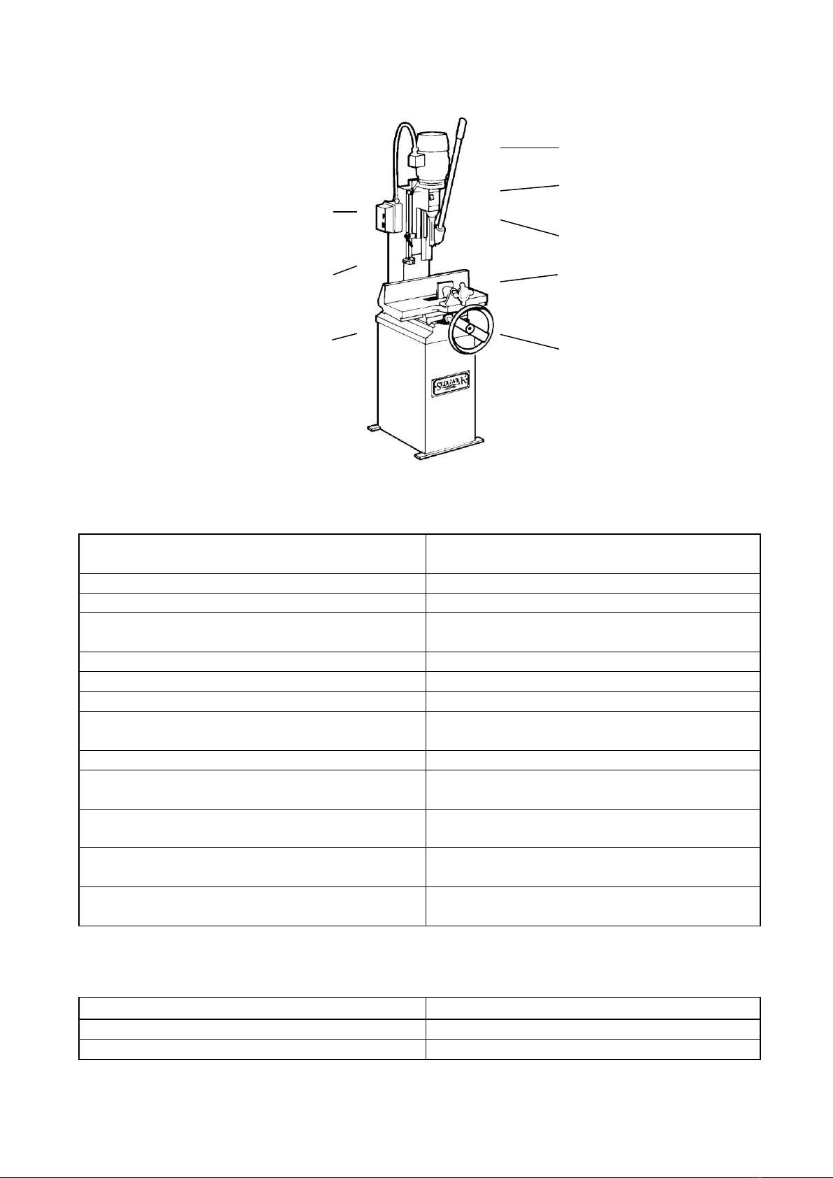
Illustration
1.2 Machine Specification
MAXIMUM CHISEL SIZE - IN HARDWOOD
IN SOFTWOOD
19mm
25mm
TIMBER CAPACITY
255x200mm
STROKE OF CHISEL HEAD
120mm
TABLE MOVEMENT -LONGITUDINAL
-LATERAL
430mm
80mm
DEPTH STOP
STD
HAUNCH STOP
STD
LENGTH STOPS
STD
VOLTAGE / FREQUENCY
3 PHASE + EARTH; 400/230 V –50/60 Hz
1 PHASE + N + EARTH ; 230V / 50/60 Hz
MOTOR RATING
1.1Kw
MOTOR FULL LOAD CURRENT IN AMPS
3 PH 2.5A
1 PH 6.6A
STARTING CURRENT IN AMPS
3 PH 15.0A
1 PH 39.6A
REQUIRED FUSE SIZE IN AMPS
3 PH 10A/ph
1 PH 20A
REQUIRED CABLE SIZE
3 PH 2.5mm2
1 PH 2.5mm2
1.3 Shipping Details
DIMENSIONS - Length x Width x Height
735x630x1520mm
NETT WEIGHT
160 Kg
Total Weight, including Packing Crate
221 Kg
OPERATING LEVER
CHUCK GUARD
CHISEL BRACKET
ADJUSTMENT
TIMBER CLAMP
LONGITUDINAL AND LATERAL
ADJUSTMENT OF TABLE VIA
SINGLE HANDWHEEL
STOP/START BUTTONS
DEPTH AND HAUNCH STOPS
LENGTHS STOPS

571 Operation/Maintenance Instructions Page 6 of 19
1.4 Personal Protective Equipment (PPE)
Operators of the machine should observe Health & Safety guidance as to use of PPE when
operating the machine, in particular:
Use of protective clothing e.g. tear-resistant sturdy overalls.
Use of protective footwear e.g. wear safety shoes with protective toes and
sturdy grips which are penetration resistant
Gloves –avoid wearing gloves when operating the machine to avoid the gloves
getting caught;
Hair - persons with long hair should tie their hair up and wear a hairnet (to avoid
the risk of hair being tangled on the machine);
Ears - wear hearing protection such as earplugs or earmuffs to avoid exposure to
noise
1.5 Residual Risks
The machine is considered operationally safe when used in accordance with this manual
however the following residual risks should be considered and adequate steps taken to
ensure such risks are minimised:
The machine is powered by electricity. Before carrying out any maintenance, cleaning
or repair work to the machine, ensure the machine is switched off and cannot be
inadvertently switched on again. If work is required on any electrical component of the
machine, ensure that the voltage supply is completely isolated. Do not remove any
safety devices or alter them to prevent them from functioning correctly.
Electrical energy can cause serious risk to health. Damaged
or broken electrical insulation materials (e.g. cabling) or
individual components (e.g. the motor/starter) can cause
electrical shocks which can cause death.
• Risk of injury from contact with the chisel
• Risk of injury through accidental contact with rotating parts –do not attempt to
remove any guarding from the machine during machining
• Risk of injury due to ejected workpieces
• Hearing damage as a result of exposure to high noise levels – take precautions
• Damage to lungs due to the inhalation of dust, which can vary when working with
different types of wood/wood with varying moisture content.
The following section offers a guide to transporting, assembling, and installing the machine.
These are all skills that should not be attempted by those who have not received relevant
training.
571 Operation/Maintenance Instructions Page 7 of 19
2.0 Machine Handling
The following section offers a guide to transporting, assembling and installing the machine,
which should be done following an adequate risk assessment. Movement, adjustment or
installation of the machine should not be attempted without proper training in the handling of
heavy machinery.
There is a risk of physical injury when moving the machine. The machine could
be damaged or written-off if not handled properly during transportation.
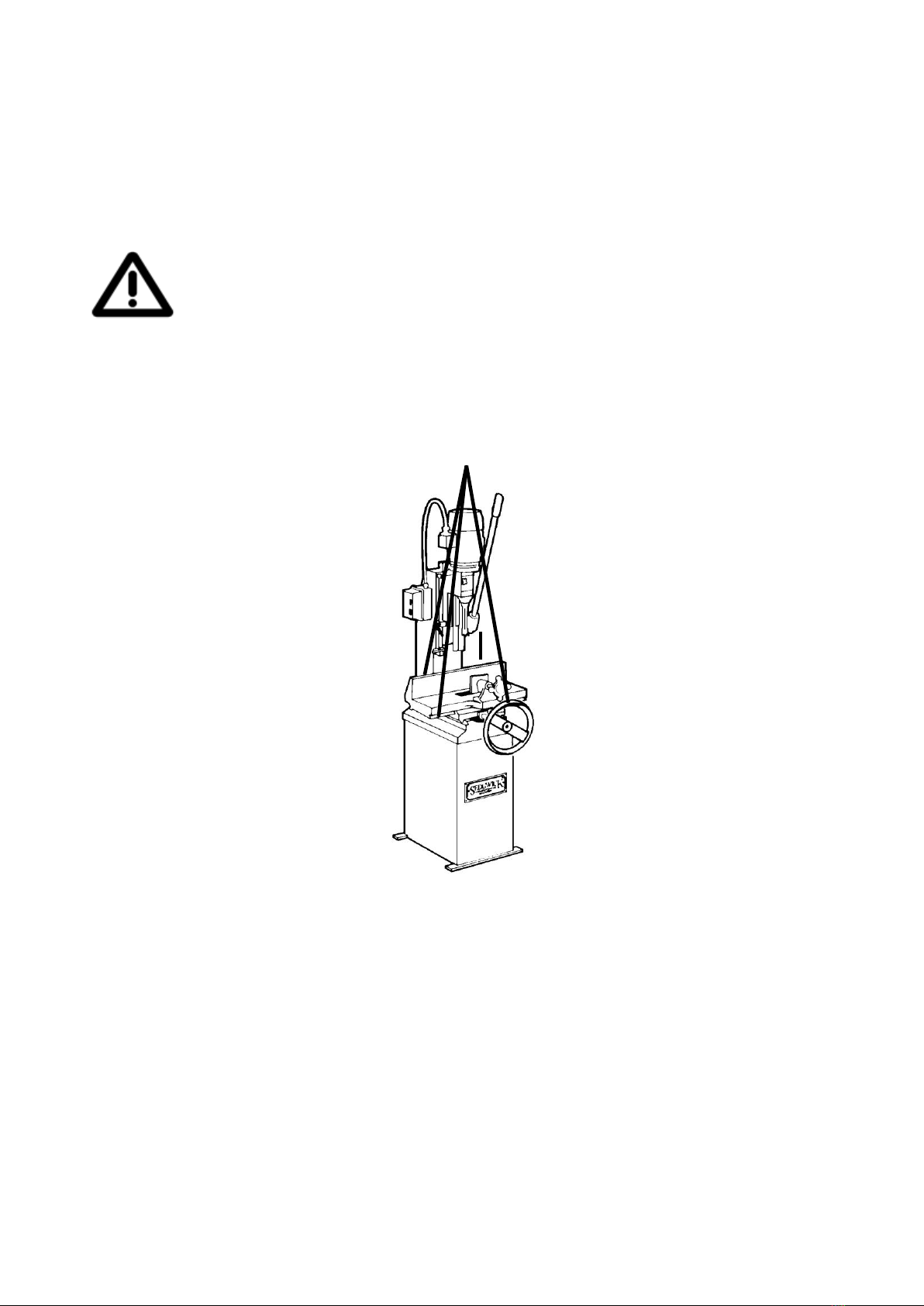
Always use a sling or hoisting device equipped with safety hooks within the safe working load of
the machine weight. Check the sling is in good condition before starting the handling operation.
Machine weights are provided in 1.3 above. Sling underneath either side of the machine table,
ensuring that you do not catch the starter etc. Do not walk or stand under the machine during
lifting.
Upon arrival, check that the machine has not suffered any damage during transit. Reuse or
recycle any packaging materials, e.g. wooden pallet, and where not possible to do so, dispose
of them in accordance with local refuse requirements.
2.1 Positioning
Around every aspect of all woodworking machines there should be clear and unobstructed space
to enable the work being done at the machine to be done without risk of injury to operators.
Consider the position of the machine, with regard to other fixed equipment and walls.

571 Operation/Maintenance Instructions Page 8 of 19
You must ensure that there is an ample power supply available to operate the machine,
together with good lighting and ventilation. Do not operate or store the machine outdoors.
Ensure the environment for operating woodworking machinery is kept clean and tidy and damp-
free. Only operate the machine in ambient temperatures.
The chosen floor space on which to site the machine should be in good and level condition to
enable the machine to be anchored at four points. Holes for M10 foundation bolts (not supplied)
are provided in the machine base. Level the tabletop by packing under the feet of the base as
required. The following drawing shows a lay-out of the anchor openings:
340mm
440mm
160mm
310mm
215mm
215mm
Table Movement

571 Operation/Maintenance Instructions Page 9 of 19
3.0 Installation
1. Remove the protective rust preventative using turpentine or paraffin. Do not use any solvent,
petrol or gas oil, which might dull or oxidise the paintwork. Lightly oil cleaned surfaces to
prevent rusting.
2. The counterbalance weight is fastened to the inside of the machine stand for transport
purposes and should be released prior to operation. Remove the bolt at the rear of the stand
whilst at the same time exerting downward pressure on the operating lever, this will enable
the weight to drop safely into its operating position.
3. Take the oil nipples from the toolkit and insert them into the two M8 tapped holes at the
centre of the rear of the column.
4.0 Electrical Installation
Electrical wiring should be carried out by a competent electrician following the directions given
below. Reference should be made to the appropriate wiring installation rules, e.g. in the UK the
16th edition of the IEE Wiring Regulations for Electrical Installation (BS7671).
The motor and starter have been wired in at the factory and tested before despatch.
All that is required is to connect the power supply to the starter from your isolator.
Check that the supply details on the motor plate correspond with the site supply.
It is important that the correct cable size is used to avoid a voltage drop at the motor
terminals. If the motor is operated on a voltage outside, plus or minus 6% of the spot
voltage, then premature failure will occur.
It is important to check rotation of the motor which should be clockwise when viewed
from above the machine.
Should you encounter problems on start up check for the following likely causes:
PROBLEM
LIKELY CAUSE
CORRECTIVE ACTION
Fails to start
Main supply switched off
Overload tripped
Fuse blown
Loose wire
Coil failure
Check main switch
Reset overload
Check and replace fuses (check all
three on three phase)
Check all connections
Check circuit of hold in coil
Overload trips during
starting
Low voltage
Low voltage
Low voltage
Check supply-voltage both on no load
and on moment of switch on. Allowed
variation plus/minus 6%
Check that correct cable size has been
used to install the machine. Change if
necessary.
Long runs of cable can cause voltage
drop. Check that voltage is not outside
the minus 6% tolerance.
Re-site the machine nearer supply or
increase the cable size to compensate.
571 Operation/Maintenance Instructions Page 10 of 19
Three phase machines only:
1 fuse blown
Machine jammed
It is possible for 3 phase machines to
operate with only 2 phases of the
supply. This will create an overload
situation and will eventually cause
premature failure, this is known as
single phasing. Check all fuses.
Check spindle is free to rotate, clean
as necessary.
Slow acceleration
Low voltage
For a motor (particularly a single-phase
permanent capacitor motor) to reach
its required starting torque a healthy
line voltage is essential.
5.0 Switch Gear
5.1 Start / Stop Buttons
The motor is started by pushing the green (power on) button on the starter panel, and stopped
using the red (power off) button.
5.2 Circuit Protection
In case of a mains failure the starter is fitted with no volt release protection and will not restart
without being switched on again. The starter is also fitted with an overload protection device.
An electrical overload occurs where an electric motor is subjected to a greater load than it was
designed for. This can be caused by short circuit, by incorrect installation, or by misuse
(including poor machine maintenance). The inbuilt breaker will therefore help prevent damage
to the motor should such a situation occur. The motor cannot be restarted until the breaker has
reset itself.
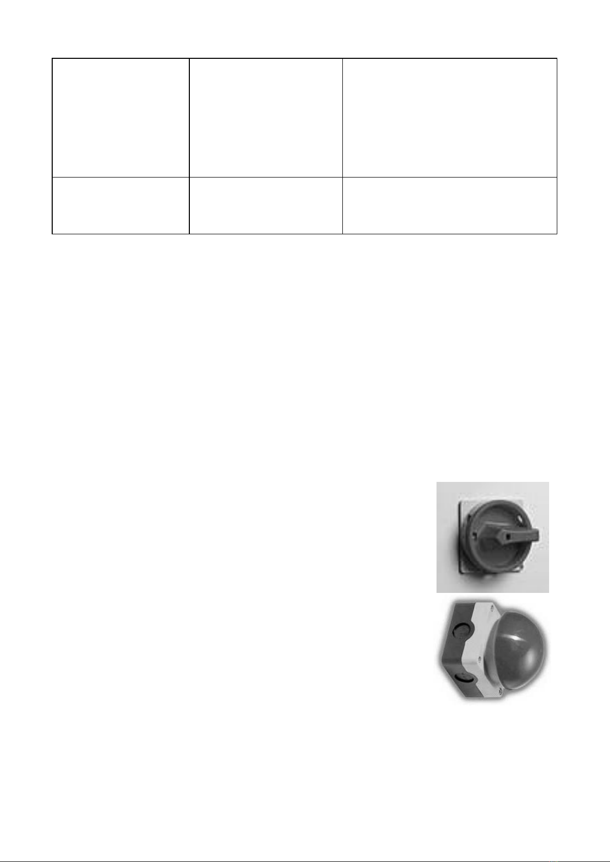
5.3 Optional Padlockable Isolator
With this switch in the OFF position the machine is effectively isolated
from the supply to allow personnel safe access for maintenance or repair
work and to prevent dangerous restarts. In order to prevent unauthorised
use of the machine the switch can also be secured in the OFF position
using a padlock.
To operate the machine, first turn the isolator to the ON position.
5.4 Optional Emergency Foot Operated Stop Switch
This switch is provided for use in emergency situations only. We do not
recommend that it is used in lieu of the stop switch on the front of the
starter panel. The foot switch, once pressed will remain locked in the off
position. To restart the machine it is necessary to release the switch by
pulling it towards you.

571 Operation/Maintenance Instructions Page 11 of 19
Controls
THE LEVER The operating lever used to control the movement of the chisel
bracket can be adjusted to suit the height of the operator as follows:
Loosen the M8 allen screw in the lever boss, slide the bar into the
correct position and re-tighten.
CHISEL HEAD The chisel bracket can be adjusted to suit the size of the work piece
as follows:
Isolate the machine. Open the chuck guard, manually support the
chisel bracket, and slacken the 24mm AF hexagon nut inside the
head with the spanner provided. Position the chisel bracket to the
required height, re-tighten the hex nut and close the chisel guard.
TABLE CLAMP The workpiece clamp can be secured in any position along the tee slot
using the locking lever provided. Its face is pre-drilled to accept a wooden
pad to help prevent possible marking of the workpiece.
TABLE MOVEMENT The table has both longitudinal and lateral movement, controlled by
the single handwheel. Push in and turn for lateral adjustment, pull out
and turn for longitudinal movement.
MORTICE DEPTH The depth of mortice is controlled by pulling the haunch stop lever
towards the operator and adjusting the collar on the stop rod to the
required depth.
Note: When cutting a deep mortice it is advisable to take the chisel down in stages of about
25mm, moving the table along for each successive cut. This enables the chisel to clear itself of
chips, and avoids subsequent overheating, particularly when cutting hard or green wood. DO
NOT OVERLOAD. The motor switch is fitted with a thermal overload cut-out, and if the motor is
overloaded will automatically switch it off. If this occurs, check the rotating parts are running
freely, and lubricate if required. If all is free then it may be necessary to reduce drilling
pressure slightly, i.e. operate at a lower rate of feed.
SETTING OUT FENCE In order to set the position of the mortice in relation to the end of the
timber the turnover stop can be adjusted either side of the table.
Note: Long or heavy timbers should be supported off the table.
MORTICE LENGTH The length of mortice may be controlled using the two length stops on
the bar at the front of the table.
571 Operation/Maintenance Instructions Page 12 of 19
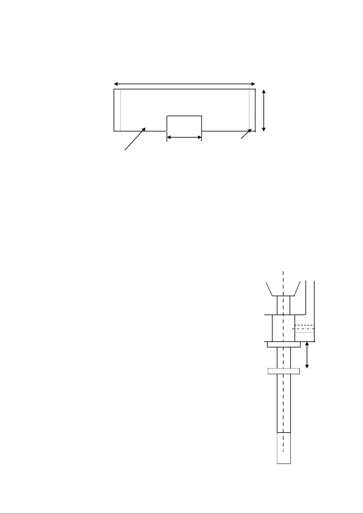
Preparation for Use
Before commencing any work on this machine it is recommended that a wooden sub table is
made as illustrated below:
560mm
105mm 25x25 Battens
12-16mm thick
Setting Up For Hollow Chisel Mortising
SEQUENCE:
1. Ensure that the machine is electrically isolated.
2. Select the correct size of chisel and auger, together with chisel bush, spanners and allen key.
3. Check that the chisel and auger have been correctly sharpened and are in good condition,
i.e. that the chisel is free from cracks and damaged points, and that the auger and cutting
edges are in good condition.
Following the guidelines below fit the chisel and auger in the chisel bracket.
Insert auger (with chisel slotted onto it) into the
adjustable chuck to its uppermost limit and tighten in
place, the chisel will then rest upon the wings of the
auger in position as shown in dotted image.
Measure dimension ‘A’ carefully, then remove the auger
and shorten its shank end by a distance 1mm less than
dimension ‘A’ measured.
Insert chisel into the chisel socket until the chisel
shoulder butts firmly up to the underface of the chisel
socket and lock screw ‘B’.
Insert auger once more to its uppermost limit. Its
scribing wings should be found to clear the chisel
internal cutting bevel by the distance allowed. Finally,
tighten the auger and the machine is then ready for
cutting.
Note: the lower point on the bit must clear the bottom
point of the chisel and not rub against the chamfer. It is
advisable to file a flat on the chisel to enable the
locking screw to grip firmly and not burr the shanks,
making removal difficult. Always ensure the chip relief
in the chisel is left to right and not front to back and
always cut away from the relief to ensure good chip
ejection.
The chisel should be mounted with its chip ejector slots
facing along the workpiece. Rotate the auger by hand to
check that it runs freely without rubbing
A
B
160mmm
m

571 Operation/Maintenance Instructions Page 13 of 19
5. Clear all tools from the machine and position the clamp as previously described.
Move the headstock down to the workpiece, to check the alignment of the chisel with the
mortice position. Set the depth stop.
6. Return the lever to the rest position. Switch on the isolator.
7. Switch on the machine and cut a trial mortice.
8. Check the mortice for position, depth and finish.
Note. A squirt of oil along the length of the auger will reduce the noise it emits when running.
Morticing Hard and Soft Woods
1. Keep the face side towards the fence.
Edge
2. Position the mortice to be cut opposite the clamp. This prevents the chisel lifting the wood
away from the table, which would occur if the mortise were too far away from the clamp.
3. Turn the workpiece ‘end to end’. This ensures that the face side is kept towards the fence
when cutting through mortise.
4. Work from both sides when cutting through mortises, as breakout on the back-edge could
occur if the chisel was taken right through. Set the chisel depth stop to enable just about a half
of the depth of mortise to be cut from each side.
5. Position the chisel about 25mm above the workpiece when the lever is in the rest position by
positioning the chisel bracket. This avoids unnecessary long movements of the headstock lever,
and reduces the effort required to produce a mortise.
6. The chuck guard must be in position.
7. Make a gradual cut when using the chisel. Remember that on the first cut all four sides of the
chisel are enclosed by the timber, making withdrawal of the chisel from the workpiece difficult.
Order of Morticing
1 2 3 4 5 6 7
Chip ejection slot facing
Face side towards
fence, mortice position
opposite cramp.

571 Operation/Maintenance Instructions Page 14 of 19
8. Do not traverse the table when the chisel is in contact with the bottom of the mortise, as this
could damage the auger and strain the mortise chisel.
9. In the interests of ease, for an extended life of mortise chisels, and for speedy working, it is
preferable to use sharp but shallow strokes on the handle, i.e. about 25mm deep for softwoods,
and 12mm deep for hardwoods. This applies particularly to wet or abrasive timber.
Faults Diagnosis
FAULT
CAUSE
REMEDY
Cuts out of square
Chisel is not square to fence
Square the chisel to the fence
Uneven bottom to mortise
Auger too far in advance of
the chisel
Reposition the auger
Chisel end blued and cracked
auger rubbing against the
auger edge, causing over
heating
Reposition the auger, regrind,
or replace the chisel
Chisel becomes hot near
centre
Bent auger
Straighten or replace the
auger
Chippings build up inside
chisel
Bad clearance. The auger
spiral does not extend far
enough, or resinous timber is
gumming up the inside of the
chisel
Remove the auger and clean
with paraffin periodically
Limitations of Use and Safe Working Practices
Training and instruction is a central requirement of the Provision of Work Equipment
Regulations 1998 (PUWER). No morticing machine can be operated by any person under the age
of 18 without them having first completed an approved course of training. The regulation does
realise that young persons may need to operate one of these machines as part of a course, and
such use is permitted provided that it is carried out under the supervision of a person who has
thorough knowledge and experience of the machine and of its safeguarding requirements.
It is essential that all operators of morticing machines are adequately trained in the use,
adjustment and operation of the machine, this covers in particular:
The dangers associated with the operation of the machine;
The principles of machine operation, correct use and adjustment of the controls;
The safe handling of the workpiece when cutting;
The position of the hands relative to the cutters and the safe stacking of the workpiece
before and after cutting.
Under no circumstances should anyone operate the machine while under the influence of
drugs, alcohol or any medication which may render them drowsy.
Persons who install this machine for use at work have a duty under the Health and Safety at
Work Act 1974 to ensure, as far as is reasonably practicable, that nothing about the way in
which it is installed makes it unsafe or a risk to health at any time during setting, use, cleaning,
and maintenance. This includes such aspects as correct assembly, electrical installation,
construction of enclosures, and the fitting of guards and ventilation equipment. When installing

571 Operation/Maintenance Instructions Page 15 of 19
this machine consideration must be given to the provision of adequate lighting and working
space.
Repairs and maintenance must only be undertaken by competent technicians. Ensure that all
power supplies are isolated before maintenance work begins. Instructions for routine
maintenance work are also included in this manual.
Health and Safety Advice
Dust
Wood dust can be harmful to health by inhalation and skin contact and concentrations of small
dust particles in the air can form an explosive mixture. These concentrations usually occur in
dust extraction equipment which may be destroyed unless explosion precautions have been
taken in the design and installation of the equipment.
Employers have duties under the Factories Act 1961, The Health And Safety At Work Act 1974
and the Control Of Substances Hazardous To Health Regulations 1988 to control wood dust in
the workplace.
Employers should carry out an adequate assessment of the possible risks to health associated
with wood dust particularly when machining hardwoods, and if necessary seek expert advice as
to the method of dust extraction.
Prevention or control of wood dust exposure should as far as is reasonably practicable, be
achieved by measure other than the provision of personal protective equipment.
Further information and references to practical guidance are contained in free leaflets from the
Health & Safety Executive, alternatively specialist help and information can be obtained from:
P&J Dust Extraction
Extraction House, Otterham Quay, Rainham, Kent ME8 8NA
Tel. 0163 423 3933 Fax. 0163 423 4588
Noise
Noise levels can vary widely from machine to machine depending on conditions of use. Persons
exposed to high noise levels, even for a short time, may experience temporary partial hearing
loss and continuous exposure to high levels can result in permanent hearing damage. The
Woodworking Machines Regulations require employers to take reasonably practicable measures
to reduce noise levels where any person is likely to be exposed to a continuous equivalent noise
level of 90 dB(A) or more over an 8 hour working day. Additionally, suitable ear protectors must
be provided, maintained and worn.
Machines identified as generating unhealthy noise levels should be appropriately marked with a
warning of the need to wear hearing protection and it may be necessary to designate particular
areas of the workplace as ‘Ear Protection Zones’. Suitable warning signs are specified in the
Safety Signs Regulations 1995. It may be necessary to construct a suitable enclosure, in which
professional advice should be sought.
Further information and references to practical guidance are contained in free leaflets available
from The Health & Safety Executive.

571 Operation/Maintenance Instructions Page 16 of 19
The list below outlines some of the variables that directly affect the noise level of the machine:
VARIABLE RELEVANT FACTOR EFFECT
Timber Species Hard stiff timber can mean more noise
(approx. 2dB(A) difference when cutting
oak and pine) & more transmitted noise.
Width Wide work pieces radiate noise over a
greater area increasing the noise level.
Thickness Thin workpieces generally vibrate more
increasing the noise level.
Length Long workpieces transmit noise away from
the cutting area towards the operator.
Tooling Width of Chisel Noise increases roughly in proportion to
the width of cut.
Tool Sharpness Dull ands worn cutters tend to chatter.
The following noise levels were recorded at a distance of one metre from the machine (operator
side) with a combination block fitted, using varying feed rates and depths of cut.
OPERATION
NOISE LEVEL dB(A) @ 1M
None
67
Cutting
70
The figures quoted for noise are emission levels and not necessarily safe working levels. Whilst
there is a correlation between emission levels and exposure levels, this cannot be used reliably
to determine whether or not further precautions are required. Factors that influence the actual
level of exposure to the work force include the duration of exposure, the characteristics of the
workroom, the other sources of dust and noise, etc., i.e. the number of machines and other
adjacent processes. Also the permissible exposure levels can vary from country to country. This
information, however, will enable the user of the machine to make a better evaluation of the
hazard and risk.

571 Operation/Maintenance Instructions Page 17 of 19
Maintenance and Lubrication
Electrically isolate the machine and ensure that all spindle movement has ceased before
carrying out any maintenance operation.
Since your morticer is constructed of cast iron, which is a porous metal, care should be taken
when cleaning. Use mineral spirits and steel wool on all metal parts. Avoid contact with
anything moist. Don’t set drinks on the tabletop, or leave green wood on it. These will leave
permanent marks.
Waxing the table surface will help resist moisture. Avoid products that contain silicone, anti-slip
additives, or abrasives.
Clean the interior of the machine stand frequently to prevent the accumulation of chips and
sawdust.
Once clean, lubricate moving parts using a lubricant that does not pick up a lot of sawdust. Pay
particular attention to the slides, operating screws and oil nipples (for the oil nipples use a
grease gun filled with oil). Powdered graphite, hard wax or white lithium sprays are ideal. Do
not use an oil-based product. These will collect sawdust and congeal into a gummy substance,
making working parts hard to operate.
Should, after long use, the tables or headstock develop a degree of side play, this can be
rectified by slackening slightly the retaining bolts on the slide concerned, and tapping the slide
until side play is eliminated, but taking care not to interfere with normal movement. Tighten
retaining bolts firmly after adjustment.
571 Operation/Maintenance Instructions Page 18 of 19
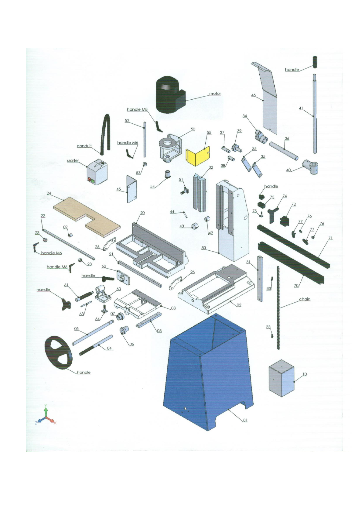
Parts Diagram

571 Operation/Maintenance Instructions Page 19 of 19
Parts List
Base & Cross Slide Assembly
571-42 DEPTH STOP POST
571-01 STAND PTD DK BLUE
571-43 DEPTH STOP CAP
'SEDGWICK' LOGO SCL027
571-44 DEPTH STOP LEVER
571-02 BASE
HANDLE I.580/40 N-8
571-03 CROSS SLIDE
571-45 STARTER BRACKET
571-04 CROSS SLIDE SCREW
571-3 STARTER 415/3/50
SPRING COMP 8DIA X 25
571-1 STARTER 230/1/50
STEEL BALL DIA 5/16INS
571-46 COLUMN COVER
571-05 HANDWHEEL SHAFT
Chisel Head Assembly
HANDWHEEL DIA 250
571-50 CHISEL HEAD
571-06 GEARCUT PINION LONG
MOTOR 1.1KW 3000RPM FLNG MOUNT 3ph
571-07 GEARCUT PINION SHORT
MOTOR 1.1KW 3000RPM FLNG MOUNT 1ph
571-08 CROSS SLIDE VEE STRIP
CHUCK ADJUSTABLE 0-13MM
571-09 LENGTH STOP
CHUCK KEY
571-10 WEIGHT
571-51 TEE BOLT
CHAIN 69 PITCHES EX CONN
SPANNER 24MM SINGLE END
CHAIN CONNECTORS
571-52 DEPTH STOP SHAFT
Table Assembly
571-53 DEPTH STOP COLLAR
571-20 TABLE
LOCKING LEVER M8X20
571-21 GEARCUT RACK
571-54 CHISEL BUSH
571-22 LENGTH STOP SHAFT
571-55 CHUCK GUARD PTD YELLOW
571-23 LENGTH STOP COLLAR
Clamp Assembly
LOCKING LEVER M6X12
571-60 CLAMP BRACKET
571-24 TABLE WOOD
571-61 CLAMP SCREW
571-25 TABLE VEE STRIP
THREE ARM KNOB DIA 16
571-26 LENGTH STOP SUPPORT
571-62 CLAMP PAD
Column Assembly
571-63 CLAMP PAD STEADY
571-30 COLUMN
571-64 CLAMP TEE-BOLT
571-31 COLUMN VEE STRIP
LOCKING LEVER M12
571-32 CHISEL HEAD SLIDE
Setting-Out Attachment Assembly
571-33 ANCHOR PINS
571-70 Setting Out Rail
571-34 CAM LEVER
571-71 Setting Out Rail Inner
571-35 LINKS
571-72 Setting Out Rail Extn Pce
571-36 CAM SHAFT
Wingnut M8x16
571-37 LINK PIN TOP
571-73 Turnover Stop Body
571-38 LINK PIN BOTTOM
571-74 Turnover Stop
571-39 BALANCE PULLEY
571-75 Tee-Bolt
571-40 LEVER BOSS
571-76 Loose Nut
571-41 LEVER
HANDLE I.580/90 N-16
Machine Identification
Your machine has an individual serial number stamped on the top surface of the rear wall of the
table. This number can also be found on the front cover of this manual. Always quote your
serial number when applying for spare parts etc.
Other manuals for 571
1
Table of contents
Other Sedgwick Industrial Equipment manuals


Popular Industrial Equipment manuals by other brands

PCB Piezotronics
PCB Piezotronics 353B14 Installation and operating manual

laguna
laguna Plasma Level 2 CNC owner's manual

Langmatz
Langmatz EK278 Installation and assembly instructions

ABB
ABB HT842008 Operation manual

Hitachi
Hitachi P1 Basic instruction manual

Metso
Metso LOKOTRACK LT110C instruction manual


