Sedgwick SM255t Troubleshooting guide

SM255t
SPINDLE MOULDER
OPERATION AND MAINTENANCE
INSTRUCTIONS
M. SEDGWICK & COMPANY LIMITED
Stanningley Field Close, Leeds, U.K. LS13 4QG
Tel. +(44) 113 257 0637 Fax. +(44) 113 239 3412
MACHINE SERIAL NO. SM255t-B

SM255t Operation/Maintenance Instructions Page 2 of 32
EC Declaration of Conformity
The manufacturer:
M. Sedgwick & Co. Ltd
Stanningley Field Close, Leeds LS13 4QG
United Kingdom
Telephone +44 113 257 0637
www.sedgwick-machinery.co.uk
Email: admin@sedgwick-machinery.co.uk
declares that the Sedgwick SM255t Spinde Moulder, when installed, maintained and used in
applications for which it was designed, and in compliance with the manufacturer’s
instructions, complies with the provisions of the following European Union legislation,
wherever applicable:
2009/127/EC Machinery Directive
2014/30/EC Electromagnetic Compatibility Directive
BS EN ISO 19085-1:2017 Safety of Machinery. Basic Concepts, General Principles of
Design. Basic Terminology, Methodology.
EN ISO 19085-6:2017 Single spindle vertical moulding machines ("toupies")
EN 60204-1:2018 Safety of machinery. Electrical equipment of machines. General
requirements
Signed for and on behalf of the manufacturer:
Managing Director
M. Sedgwick & Co. Ltd, Jan 2021

SM255t Operation/Maintenance Instructions Page 3 of 32
List of Contents
1.0 Design and Purpose
1.1 Illustration
1.2 Machine Specification
1.3 Shipping Details
2.0 Installation Instructions
2.1 Positioning
2.2 Foundation Drawings
3.0 Connection to a Dust Extraction System
4.0 Electrical Installation
5.0 Switchgear
5.1 The Padlockable Isolator
5.2 Start/Stop Buttons
5.3 Circuit Protection
5.4 Emergency Foot Operated Stop Switch
6.0 Machine Setting
6.1 The Spindle Rise & Fall
6.2 The Loose Top Spindle
6.3 Direction of Rotation
6.4 Table Inserts
6.5 Speed Selection
7.0 Tool Selection
7.1 Tool Setting
7.2 Tool Handling
7.3 Tool Repair
8.0 Machine Guards
8.1 The Main Fence Guard
8.2 The Cutterguard
8.3 The Shaw Guards
8.4 Push Sticks & Push Blocks
9.0 Limitations of Use and Safe & Working Practices
9.1 Warning of Residual Risk
9.2 Warning Labels
9.3 Noise Reduction
10.0 Maintenance
10.1 Cleaning and Lubrication
10.2 Brake Motor Installation & Maintenance
11.0 Parts List

SM255t Operation/Maintenance Instructions Page 4 of 32
Introduction
This Instruction Manual is designed for you in accordance with current UK regulations and EU
law, in particular the European Machinery Directive 206/42/EC.
It describes how to operate the machine properly and safely. Be sure to read carefully and
follow the safety instructions provided as well as any local accident prevention regulations
and general safety regulations. Before beginning any work on the machine, ensure that this
manual, in particular the chapter entitled "Safety" and the respective safety guidelines, has
been read in its entirety and fully understood. This manual is an integral part of the machine
and must always be kept accessible. If the machine is sold, rented, lent or otherwise
transferred to another party, a copy of the manual must accompany it.
All those appointed to work on or with the machine must have fully read and understood the
manual before commencing any work. This requirement must be met even if the appointed
person is familiar with the operation of such a machine or a similar one or has been trained
by the manufacturer. The manufacturer cannot be held liable for damages resulting from a
failure to follow the instructions set out in this manual. Should you have any questions
regarding this manual, please contact the manufacturer.
1.0 Design and Purpose
The Sedgwick SM255t Spindle Moulder is a hand fed machine designed to profile wood and
other analogous materials. Such operations may include:
1. Straight Moulding e.g., rebating, bevelling, and grooving.
2. Circular Moulding (optional Ring Fence and Cage Guard required).
3. End Grain Work e.g., Tenoning and Finger Jointing (optional Sliding Table required).
The machine is not designed for any other purposes except as set out above. The
operator of the machine shall be solely liable for any damage that results from
improper use of the machine.
The machine should not be modified in any way without the written consent of the
manufacturer. Please also refer to Section 11.0 regarding use of unauthorised spare parts.
SM255t Operation/Maintenance Instructions Page 5 of 32
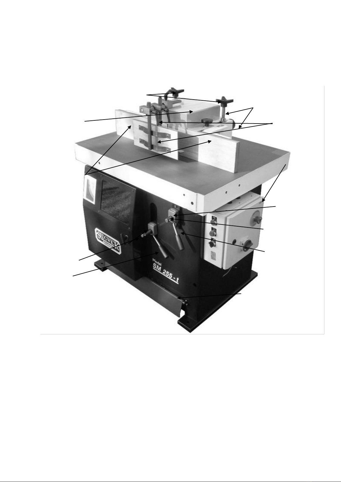
1.1 Illustration
FENCE HOLD DOWN HANDLES
EXTRACTION OUTLETS
CUTTERGUARD SHAW GUARDS
SWITCHGEAR/
ISOLATOR
FENCE PLATES
SPINDLE HEIGHT
INDICATOR
RISE & FALL HANDLE
SPINDLE ANGLE INDICATOR
SPINDLE R & F LOCK
TILT HANDLE
TILT LOCK
FOOT STOP SWITCH

SM255t Operation/Maintenance Instructions Page 6 of 32
1.2 Machine Specification
SM255T
TABLE SIZE L x W
1000 x 750mm
TABLE HEIGHT
880mm
MAX CUTTERBLOCK DIA.
150mm
MAX PROFILING CUTTER DIA.
255mm
MAX CUTTER WEIGHT
7Kg
MAX RETRACTABLE TOOL SIZE
180 x 65mm
SPINDLE DIA.
30mm (Optional 11/4”)
SPINDLE LENGTH
180mm
SPINDLE SPEEDS rpm
3000/4500/6000/8000
SPINDLE STROKE
90mm
FENCE PLATES (H x L)
150x425mm
DUST EXTRACTION OUTLETS
125 & 100mm
TOTAL AIR VOLUME REQUIRED
(Straight work)
1 100
VOLTAGE/FREQUENCY
3 PHASE+EARTH; 400/230v –50/60
Hz
1 PHASE+N+EARTH; 230V - 50/60 Hz
MOTOR RATING
3 PHASE 5.5Kw IE2 (S1)
1 PHASE 3.8Kw
MOTOR FULL LOAD CURRENT IN
AMPS
3 PHASE 8.0A
1 PHASE 16.5A
STARTING CURRENT IN AMPS
3 PHASE 48A
1 PHASE 99A
REQUIRED FUSE SIZE IN AMPS
3 PHASE 20A/ph
1 PHASE 40A
REQUIRED CABLE SIZE
3 PHASE 2.5mm2
1 PHASE 4.0mm2
1.3 Shipping Details
DIMENSIONS (m/c only) LxWxH
1120x760x1440mm
NETT WEIGHT
425 kg

SM255t Operation/Maintenance Instructions Page 7 of 32
2.0 Machine Handling
The following section offers a guide to transporting, assembling, and installing the machine,
which should be done following an adequate risk assessment. Movement, adjustment, or
installation of the machine should not be attempted without proper training in the handling
of heavy machinery.
There is a risk of physical injury when moving the machine. The machine could
be damaged or written-off if not handled properly during transportation.
Always use a sling within the safe working load of the machine weight. Machine weights are
provided above. Sling underneath either side of the machine table, ensuring that you do not
catch the starter etc. Take care not to lift the machine by the slide bar on the front of the
machine table (if fitted) as damage to this will inhibit the movement of the sliding table. Do
not walk or stand under the machine during lifting.
Upon arrival, check that the machine has not suffered any damage during transit. Reuse or
recycle any packaging materials (e.g., wooden pallet) and where not possible to do so,
dispose of them in accordance with local refuse requirements.
2.1 Positioning
First ensure that there is ample power supply available, together with good lighting and
ventilation.
Second ensure that there is sufficient unobstructed space around the machine to enable the
work being done at it to be done without risk of injury to persons employed.
The chosen floor space should be in good and level condition to enable the machine to be
anchored at four points. Holes for M10 foundation bolts (not supplied) are provided at either
corner of the inside of the fabricated body. Remove the machine’s side guard, score marks
through these holes, drag the machine out of the way, and drill the necessary holes and
insert fixing plugs. Finally, make sure that the machine is not rocking. Pack under the feet of

SM255t Operation/Maintenance Instructions Page 8 of 32
the base if it is. This will keep the machine from rocking and generating vibration during the
cut.
2.2 SM255t Foundation Drawings
Remove the protective rust preventative using turpentine or paraffin. Do not use any solvent,
petrol, or gas oil, which might dull the paint or oxidise the paintwork. Lightly oil cleaned
surfaces to prevent rusting.
2.2 Storage
Keep the machine sealed in its original packaging until required for assembly/installation and
be sure to observe the machine handling advice on the outside of the packaging.
Store under the following conditions:
• Store indoors in a dry and dust-free environment.
• Do not expose to toxic substances or direct sunlight.
•Store in ambient temperatures and ensure environment is not damp; avoid exposure to
condensation.
• If storing for a period of several weeks, apply a coat of oil to all machine parts that might
rust before storing and check condition before operating for the first time after being in long-
term storage.
2.3 Disposal
If disposing of the machine, separate all components into piles of the same material e.g.,
steel, to recycle. The main structure is made of cast iron and steel and can therefore be
safely dismantled and recycled. Always comply with local environmental regulations when
disposing of machinery.
Be aware of your environmental obligations. Carefully consider the disposal of
any electrical components e.g., motors, starters, and ensure any lubricants etc.
are treated as hazardous waste and disposed of safely in accordance with
environmental laws.

SM255t Operation/Maintenance Instructions Page 9 of 32
3.0 Connection to a Dust Extraction System
All employers are duty bound under the Factories Act 1961, The Health and Safety at Work
Act 1974 and the Control of Substances Hazardous to Health Regulations 1988 to control
wood dust in the workplace.
Wherever possible this should be achieved by measures other than the provision of personal
protective equipment.
To effectively exhaust these machines, they should be connected to a dust extraction unit
with a minimum air volume with the chart below. A 125mm-dia outlet is located at the rear of
the fence horseshoe. A 100mm-dia outlet is provided for extraction below the cutter-well.
Always switch the dust extraction system on before switching on the machine.

SM255t Operation/Maintenance Instructions Page 10 of 32
4.0 Electrical Installation
Electrical wiring should only be carried out by a fully qualified electrician taking
in account the following safety instructions.
•The motor, starter, and isolator have been wired in at the factory and tested before
despatch. All that is required is to connect the power supply to the isolator.
•Check that the supply details on the motor nameplate correspond with the site
supply.
•It is important that the correct cable size is used to avoid a voltage drop at the
motor terminals. If the motor is operated on a voltage outside, plus or minus 6% of
the spot voltage, then premature failure will occur.
•Do not wire single-phase machines into a 13 amp plug socket.
•It is important to check rotation of the spindle which should be anti-clockwise when
viewed from the front of the machine.
Should you encounter problems on start-up check for the following likely causes:
Symptom
Check
Machine does not start at all.
Isolator is switched to ON and all STOP buttons are out.
Overload button is reset.
Starter coil/contactor is operational.
There are no loose connections.
There are no fuses blown.
Supply is reaching the starter.
Supply is reaching the motor.
Voltage between the phases at starter and motor.
Motor runs but trips.
Overload setting in starter.
Current drawn without load applied.
Current drawn under load.
Supply voltage without load and on moment of switch on.
Allowed variation plus/minus 6%.
Supply voltage under load.
Supply voltage with motor off.
Supply to all three phases at isolator, starter and at motor.
Note that it is possible for 3 phase machines to operate
with only 2 phases of the supply. This is known as single
phasing. Check all fuses.
Motor attempts to start then
trips.
The machine is not jammed, and the spindle is free to
rotate.
Winding resistance of each motor phase (values should all
balance).
Insulation resistance between windings and earth.
The correct cable size has been used to install the
machine (long runs of cable can cause voltage drop).

SM255t Operation/Maintenance Instructions Page 11 of 32
4.1 Three Phase Wiring Diagram

SM255t Operation/Maintenance Instructions Page 12 of 32
4.2 Single Phase Wiring Diagram
SM255t Operation/Maintenance Instructions Page 13 of 32
5.0 Switch Gear
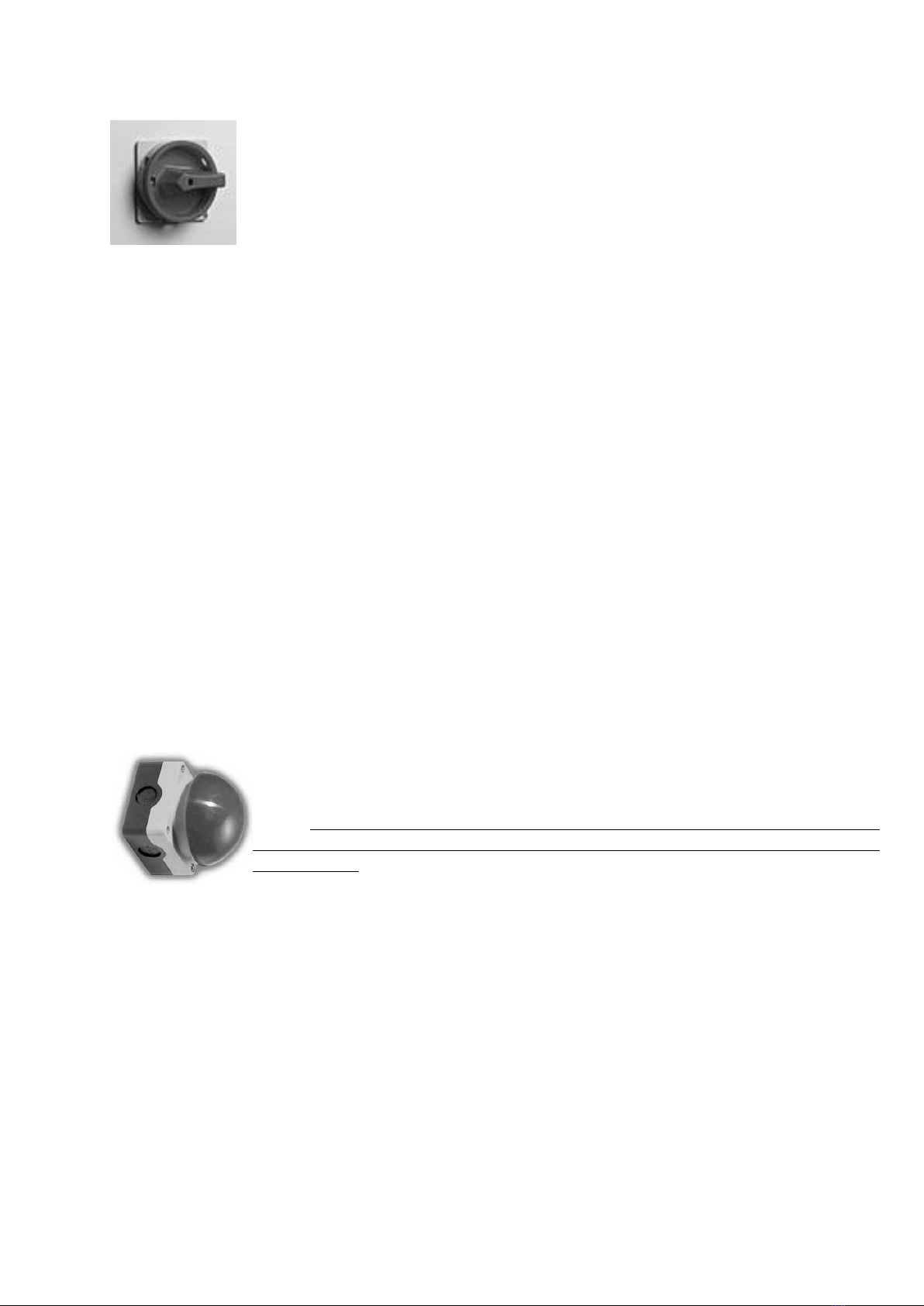
5.1 The Padlockable Isolator
With this switch in the OFF position the machine is effectively isolated from the
supply to allow personnel safe access for maintenance or repair work and to
prevent dangerous restarts. To prevent unauthorised use of the machine the
switch can also be secured in the OFF position using a padlock.
To operate the machine first turn the isolator to the ON position.
5.2 Start / Stop Buttons
The motor is then started by pushing the green (power on) button on the starter panel and
stopped using the red (power off) button. The mushroom headed lock-off stop switch, once
pressed will remain locked in the off position. To restart the machine, it is necessary to release
the off button by twisting it in a clockwise direction.
5.3 Circuit Protection
In case of a mains failure the starter is fitted with no volt release protection and will not restart
without being switched on again. The starter is also fitted with an overload protection
device. An electrical overload occurs where an electric motor is subjected to a greater load
than it was designed for. This can be caused by short circuit, by incorrect installation, or by
misuse (including poor machine maintenance). The inbuilt breaker will therefore help prevent
damage to the motor should such a situation occur. The motor cannot be restarted until the
breaker has reset itself.
5.4 Brake Release Switch
Machines fitted with an electro-magnetic brake unit are also equipped with a ‘Brake
Release’ switch. This switch makes it possible to release the brake mechanism, allowing the
operator to rotate the spindle when changing or adjusting the cutting knives. To operate the
switch first turn the isolator to ON, release the mushroom headed lock-off stop switch, and
turn the brake release to ‘BRAKE RELEASE’. It is not possible to start the motor with the switch
in this position. To start the motor, turn the switch back to the RUN position.
5.4 Emergency Foot Operated Latching Stop Switch
This switch is provided for use in emergency situations only. We do not
recommend that it is used in lieu of the stop switch on the front of the starter
panel. The foot switch once pressed will remain locked in the off position. To
restart the machine, it is necessary to release the switch by pulling it
towards you.
SM255t Operation/Maintenance Instructions Page 14 of 32
6.0 Machine Setting
Details on the correct setting of the guards, fences, and other safety devices, are detailed in
the following sections of this manual. Prior to these operations however the following checks
should be carried out:
1. Isolate the machine before setting up or making any alterations.
2. Ensure that the arbor mounting, cutterblock and cutters are clean and free from grease,
rust preventative, rust and wood residue etc.
3. Check visually for any cracks or distortion in the cutters and replace any suspect
components.
4. Check that the cutters are mounted correctly for anti-clockwise rotation when viewed
from the front of the machine.
5. The fence assembly and spindle guards are securely fastened to the table.
6. The timber is free of grit, nails or other foreign bodies.
7. The table is free of spanners, rules etc., and that all tools are returned to their rightful
place.
ENSURE THAT ALL STOCK IS CLEAR OF THE BLADE BEFORE START-UP
ENSURE THAT THE SPINDLE HAS REACHED FULL SPEED BEFORE PRESENTING THE WORKPIECE TO
IT. IT IS ESSENTIAL THAT THE MACHINE IS SWITCHED OFF WHEN LEFT UNATTENDED.
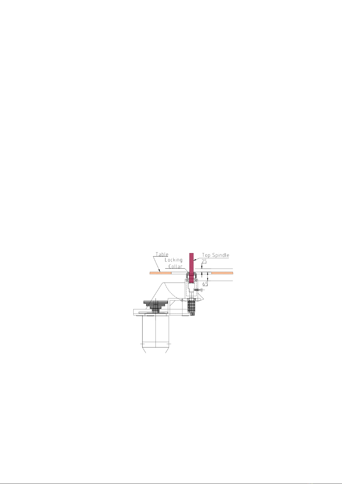
6.1 The Spindle Rise and Fall and Tilt
To adjust the spindle height, first untighten the Spindle Lock positioned directly behind the
handwheel. Rotate the handwheel clockwise for up, and anti-clockwise for down.
The range of adjustment is =25mm above the Table and -65mm below referenced to the
Locking Collar surface from which the cutter blocks may be mounted.
Always make final adjustments to the spindle height against gravity and re-tighten the
Spindle Lock prior to start-up.
Stiffness in the rise and fall movement could be caused by:
1. The Spindle Lock not releasing or being released.
2. Dirt or rust between the barrel and the bearing housing.
3. A lack of lubrication.
4. Badly worn gears (usually the result of an effort to force the rise and fall mechanism
when stiff).
5. Dirt between the gear teeth.
6. Offcut wedges between the slideways.

SM255t Operation/Maintenance Instructions Page 15 of 32
On the Sedgwick SM255t the complete motor and spindle sub-assembly tilts independently
of the Rise and Fall mechanism. The tilt action rotates about the centre line of the spindle at
the locking collar surface, the operator therefore maintains the same depth of wood cut
irrespective of whether a new height of cut is chosen.
The operator is provided with stops at =%, 0 and -45 degrees. At the zero stop the operator
must hand withdraw the Zero Stop Plunger to enable further tilt, either in the +5 or -45
direction.
6.2 The Spindle Unit
The loose top spindle onto which the cutters are mounted is attached to the main spindle by
a draw bar. To remove the loose top spindle, first isolate the machine. Open the cabinet
door. Using the two 19mm spanners, one set on the flats of the loose spindle, the other on the
bolt head at the bottom of the spindle pulley, untighten the bolt. This enables the loose top
spindle, complete with cutters, spacing sleeves, and lock nut to be removed as a unit from
the machine without disturbing their setting. Use only the spanners supplied with the
machine. Never add extra leverage as this strains the bolts and leads to excessive wear.
If several months pass between spindle changes it is good practice to wipe a light film of oil
over the spindle base before installing it in the arbor.

SM255t Operation/Maintenance Instructions Page 16 of 32
6.3 Direction of Rotation
The machine spindle is designed for one direction of rotation only. The rotation should be
anticlockwise when viewed from the top.
It is most important that the tooling is fitted to the machine to operate in the correct direction
of rotation. The operator shall ensure that the workpiece is fed to the tools against the
direction of spindle rotation. To reduce the risk of kickback, always start the machine before
presenting the workpiece. Ensure that the machine is switched off when left unattended.
6.4 Table Inserts
Use the table rings provided to reduce the gap between the table and the spindle to a
minimum. Correct use of the table rings to give the smallest possible hole reduces the risk of
the workpiece dipping and catching the edge as it passes over the gap.
6.5 Speed Selection
The relationship between the tool diameter, the cutting length and the maximum rotational
speed of the spindle is important. This can be determined from the following graph:
To obtain the different spindle speeds required for the various diameters and types of cutter
equipment simply alter the position of the drive belt again the pulley ratio.
This unit is totally enclosed within the main frame and is accessed via the door on the front of
the machine’s body.
It is important that all spindle motion has ceased, and the machine has been electronically
isolated before opening this door.

SM255t Operation/Maintenance Instructions Page 17 of 32
The motor is face mounted to a hinged platform, which is adjustable for position along a slot
in which the locking lever runs. To change the selected speed the lever must be unlocked,
and the motor plate pulled forward to release the tension on the drive belt. The poly-vee belt
may then be relocated on the pulleys, the motor plate pushed away to re-tension the belt,
and the lever re-locked. Always ensure that the belt is fully engaged within the full set of
grooves for each speed setting on both motor and spindle pulleys before starting the
machine.
7.0 Tool Selection
Only tools conforming to EN847-1:1997 and marked MAN should be fitted to this machine
(refer to manufacturer’s sales literature).
Only use tooling with the manual feed cutter blocks usually mark with ‘MAN’.
LIMITED CUTTER PROJECTION TOOLING
Where possible, always use limited cutter projection tooling.
The following information is contained in the HSE Information Sheet ‘PUWER 98: Selection of
tooling for use with hand-fed woodworking machines’:
Limited cutter projection tooling (sometimes referred to as chip thickness limitation
tooling) significantly reduces:
● the severity of injury if a machine operator’s fingers contact the rotating tool;
● the risk of workpiece kickback.
Most accidents at woodworking machines are due to the operator’s hands or fingers
encountering the rotating cutters. Amputation usually results. Between 1993 and 1996
there were 165 injuries (amputations and severe lacerations) at machines where
limited cutter projection tooling could have been fitted. It is estimated that limited
cutter projection tooling would have reduced the seriousness of injury in 90% of these
accidents. By reducing the risk of kickback, this type of tooling can also help prevent
many other serious injuries.

SM255t Operation/Maintenance Instructions Page 18 of 32
On round form tools, limited cutter projection should be achieved by restricting the
projection of the cutter beyond either:
●the round profile of the tool body
● or a ‘limiter’ (also called a deflector or counter knife) which mirrors each cutter
Note: Limited cutter projection tooling should be used in addition to the normal
guards, protection appliances (jigs etc) and safe working practices, not as an
alternative.
7.1 Tool Setting
For safety reasons the cutterhead should whenever possible be mounted to run from
underneath the stock so that the stock will cover the cutterhead and shield your hands. Set
the cutterblock as low on the spindle arbor as possible. Always use cutters that are a
matched pair and mount them directly opposite each other ensuring that they have the
same projection and are dynamically balanced. Most problems experienced on spindle
moulding machines arise from out of balance cutters, with the resulting bad feature of
excessive vibration, which tends to produce a poor finish on the article being machined.
Ensure that the correct number of spacers is used to effectively clamp the cutters.
7.2 Tool Handling
Care should be exercised when handling tools, wherever practicable use a tool carier or
wear protective gloves.
7.3 Tool Repair
Repair of tools should be carried out in accordance with the manufacturer’s instructions.
People who carry out repair of tools should be adequately trained and have knowledge of
the design requirements (eg BS EN 847-1: 1997) and levels of safety to be achieved.

SM255t Operation/Maintenance Instructions Page 19 of 32
7.4 Tool Changing
Raise the spindle to the maximum height and lock off the rise and fall using the lever next to
the rise and fall hand wheel (clockwise to lock). Using a 30mm spanner and M8 hex key
untight the hex bolt from the top of the arbor and remove the bolt and spindle nut and put
them safely to one side. Fit the cutter block by sliding it onto the arbor (check the rotation of
the block) and using the spaces and the spindle nut to clamp the cutter inplace. Tighten the
spindle nut and hex nut. Make sure that it is tighten securely.
8.1 The Main Fence Guard
The Sedgwick SM255t Spindle Moulder incorporates a plain table and a cast-iron ‘Horseshoe’
type fence guard.
Adjustment and Use
For coarse adjustment, the complete fence assembly freely moves as one. The two Fence
Hold-Down Handles effectively clamp the assembly to the table through slotted holes in the
horseshoe. The table has been drilled and tapped for several different locations. The fence
plates can be independently adjusted by releasing the locking levers at the sides of the
horseshoe, and operating the hand-wheels at the rear, remembering then to re-tighten them
once adjusted.
The gap between the two halves of the straight fence must be wide enough to give
clearance for the cutterblock yet narrow enough to limit unnecessary exposure of the
cutters. Similarly ensure that the leading end of the workpiece does not foul the edge of the
take-off half of the fence. These risks may be eliminated using a false fence.
A ‘false fence’ is a board fixed to the two half fences and spanning the gap between them,
it is cut away just sufficiently to allow the cutters to project by the necessary amount. The
exact size of false fence required will depend upon the work being done and it may be
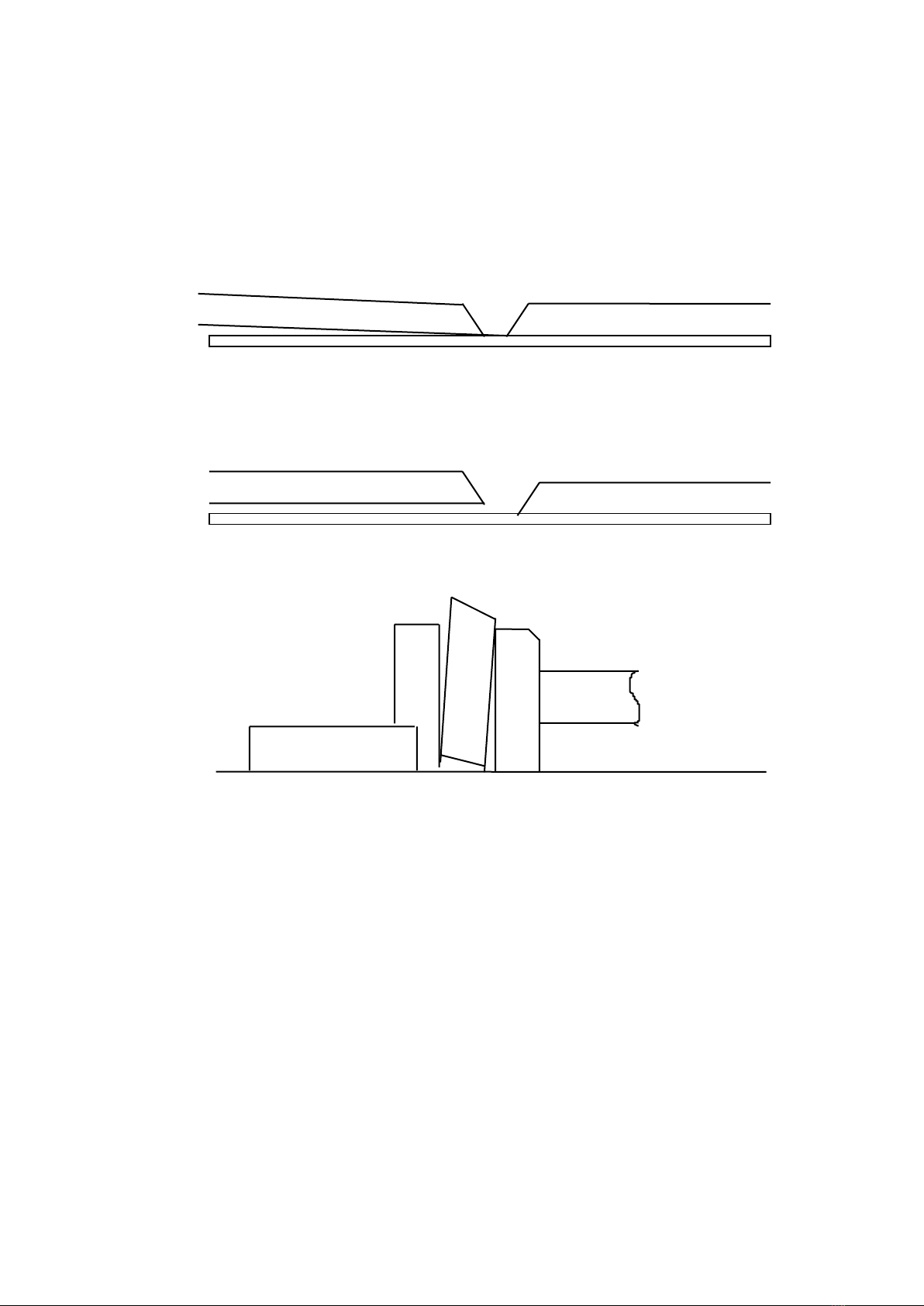
SM255t Operation/Maintenance Instructions Page 20 of 32
necessary to fit a different false fence for every job carried out. Care should be taken in the
making of a false fence. It is recommended that the cutter opening shall be made by a
controlled screw adjustment on the fence on to the cutter and not by pushing the fence on
to the cutter by hand.
The following faults in fences can occur and should be checked:
A) Fences out of alignment. Chippings packed behind the front fence plate and back
fence can cause this.
B) Fences are parallel but not level with one another. Use the fine adjustment screws to
bring them level.
C) Fences are not square against the table. Chippings at the base of the fence plate
can cause this.
8.2 The Cutterguard
The yellow hood on top of the horseshoe assembly is designed to enclose the cutting area
just above the workpiece. It is important that this is always secured in position when using the
horseshoe as it provides protection from ejected cuttings or cutters which might be thrown
off the workpiece or cutterblock while in operation.
Check that the hood is securely in position before switching on.
8.3 The Shaw Guards
The Shaw Guards are a valuable aid when machining straight work where the moulding
extends over the full length of the workpiece. They serve the dual-purpose of steadying the
workpiece, preventing vibration which could cause kick-back, and enclosing the cutting
area.
Work of this type is done with the aid of the straight fence, and in most cases the workpieces
are of regular rectangular section throughout their length. The workpieces can, therefore, be
guided in the volume formed between the Table, Shaw Guard, and fence. The vertical and
Table of contents
Other Sedgwick Industrial Equipment manuals


