Sedgwick MB Troubleshooting guide
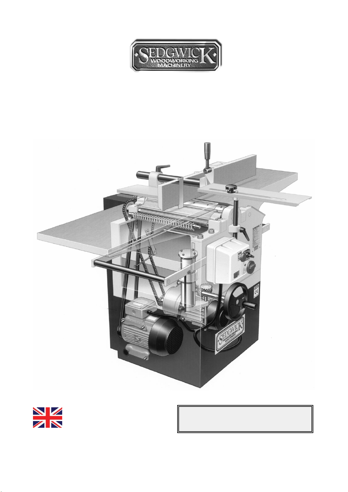
MB/CP
PLANER THICKNESSER
OPERATION AND MAINTENANCE
INSTRUCTIONS
Manufactured in Britain
MACHINE SERIAL NO.

2
DECLARATION OF CONFORMITY
ORIGINAL
Business Name and Full Address of Manufacturer
M. Sedgwick & Co. Ltd. - Stanningley Field Close, Leeds LS13 4QG
Description of product (Commercial Name)
Model MB / CP Planer Thicknesser
Function, Model, Type
Function: Woodworking Machine
Type: Planer Thicknesser
Model: MB / CP
Standards Used
BS EN 861 - 2007 + A2 2012
Place of Declaration
M. Sedgwick & Co. Ltd.
Date of
Declaration
09 May 2017
Name, Address and ID No of Notified Body
TUV SUD BABT Octagon House, Concorde Way, Segensworth North, Fareham PO15
5RL
NB # 0168
No of EC Type Examination Certificate
MAC000012 i01
Declaration
I declare that the machinery fulfils all the relevant provisions of the following
Directives:- Machinery Directive 2006/42/EC, Electromagnetic Compatibility
Directive 2014/30/EU
Person Empowered to Draw Up Declaration
Name:
G. Sedgwick
Position:
Managing Director
Signature:

3
List of Contents
1.0 Design and Purpose
1.1 Illustration
1.2 Machine Specification
1.3 Shipping Details
2.0 Handling Instructions
2.1 Positioning
2.2 Foundation Drawings
3.0 Connection to a Dust Extraction System
3.1 Chip Extraction Hood
4.0 Electrical Installation
5.0 Switchgear
5.1 The Padlockable Isolator
5.2 Start/Stop Buttons
5.3 Two/Three Position Rotary Switch
5.4 Circuit Protection
5.5 Brake Release Switch
5.6 Optional Emergency Foot Operated Stop Switch
6.0 Guarding
6.1 The Front Cutterblock Guard
6.2 The Rear Cutterblock Guard
6.3 The Rear Drive Guard
6.4 The Anti Kickback Fingers
7.0 The Cutterblock / Knife Changing
7.1 The Optional TERSA Monobloc
8.0 Preparation of the Workpiece
8.1 Pilot Checks
9.0 Surface Planing
9.1 Flatting
9.2 Planing Wide
9.3 Bowed Boards
9.4 Edge Planing (Squaring)
9.5 Bevelling or Chamfering
9.6Push Blocks and Push Sticks
10.0 Thicknessing
11.0 Diagnosing Faults in Planing
12.0 Limitations of Use and Safe & Working Practices
12.1 Noise Reduction
12.2 Warning Labels
13.0 Maintenance
13.1 Lubrication
13.2 Cutterblock & Bearings
13.3 Vee Belt and Pulleys
13.4 The Feed Rollers
13.5 Planer Tables
13.6 The Fence
14.0 Parts Illustration
14.1 Parts List
15.0 Wiring Diagrams

4
Introduction
This Instruction Manual is designed for you in accordance with The Supply of Machinery (Safety)
Regulations 1992, and the Supply of Machinery (Safety) (Amended) Regulations 1994, which
implement the European Machinery Directive 89/392/EEC.
It describes how to operate the machine properly and safely. Be sure to follow the safety
instructions provided as well as any local accident prevention regulations and general safety
regulations. Before beginning any work on the machine, ensure that the manual, in particular
the chapter entitled "Safety" and the respective safety guidelines, has been read in its entirety
and fully understood. This manual is an integral part of the machine and must therefore be kept
accessible at all times. If the machine is sold, rented, lent or otherwise transferred to another
party, a copy of the manual must accompany it.
All those appointed to work on or with the machine must have fully read and understood the
manual before commencing any work. This requirement must be met even if the appointed
person is familiar with the operation of such a machine or a similar one, or has been trained by
the manufacturer.
1.0 Design and Purpose
The MB/CP Planer Thicknesser is a dual-purpose machine designed to plane wood and similar
materials by means of a horizontally rotating cutterblock. When surfacing, the workpiece is
passed over the top of the cutterblock and the lower surface is planed. The infeed table of the
surface-planing unit is adjustable in height. When planing material to a set thickness, the wood
is passed underneath the cutterblock, supported by the thicknessing table, and the top surface
is planed.
The following operations can also be performed on the machine, and guidelines on how these
should be performed safely are provided in this manual: flatting, edging, chamfering, and
bevelling.
Any use outside of the machine's intended purpose shall be considered improper
and is therefore not permitted. All claims regarding damage
resulting from improper use that are made against the manufacturer
and its authorised representatives shall be rejected. The operator
shall be solely liable for any damage that results from improper use of the
machine.
It is expressly forbidden to make any unauthorised modifications to the machine.
5
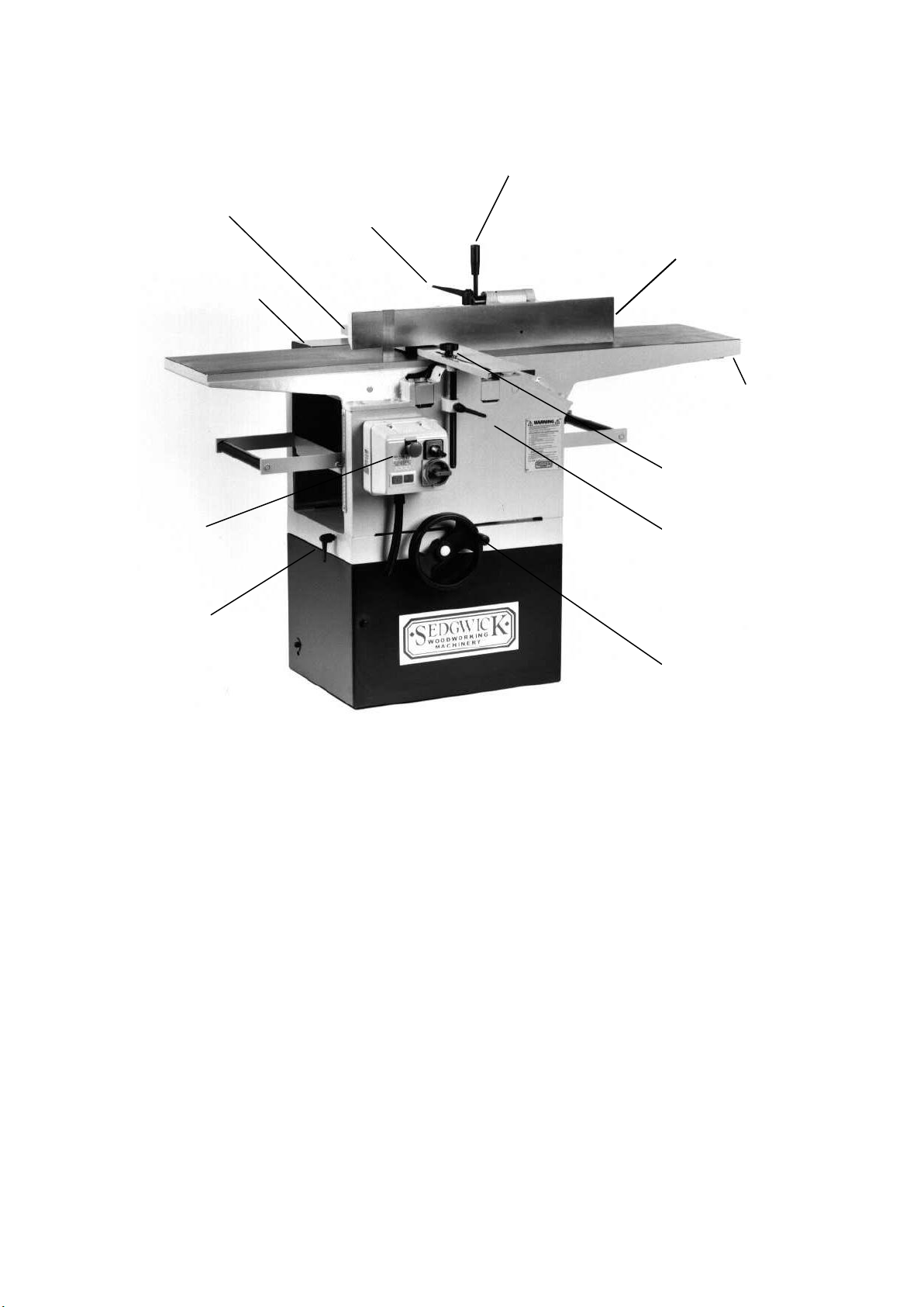
1.1 Illustration
FENCE CANT LOCK
SURFACE TABLE RISE
AND FALL HANDLE
CUTTERBLOCK
GUARD
HORIZONTAL LOCK
4
CUTTERBLOCK GUARD
VERTICAL LOCK
THICKNESSING TABLE RISE
AND FALL
THICKNESSING TABLE
VERTICAL LOCK
MOTOR SWITCHGEAR
REAR MACHINE GUARD
REAR CUTTERBLOCK
GUARD
FENCE LATERAL LOCK
SURFACE TABLE RISE AND
FALL LOCK

6
1.2 Technical Specification
MB
CP
SURFACE CAPACITY
308 mm
410 mm
THICKNESSING WIDTH
308 mm
410 mm
THICKNESSING DEPTH
230 mm
230 mm
SURFACE TABLE LENGTH
1500 mm
1700 mm
INFEED TABLE LENGTH
850 mm
850 mm
SURFACE TABLE HEIGHT
900 mm
900 mm
THICKNESSING TABLE LENGTH
600 mm
600 mm
TABLE LENGTH OVER EXTN ROLLERS
1000 mm
1000 mm
CUTTERBLOCK DIAMETER
102 mm
102 mm
CUTTERBLOCK KNIVES
3 Std (4 TERSA)
3 Std (4 TERSA)
CUTTERBLOCK SPEED
4000rpm
4000 rpm
FEED ROLLER DIAMETER
51 mm
51 mm
FEED SPEEDS
3 PHASE 4.5 & 7m/min
1 PHASE 6 m/min
3 PHASE 4.5 & 7m/min
1 PHASE 6 m/min
FENCE SIZE
900 x 140 mm
900 x 140 mm
TILTING ANGLE OF FENCE
0O–45O
0O–45O
CHIP EXTRACTION OUTLET DIA.
125mm
150mm
VOLTAGE / FREQUENCY
3 PHASE + EARTH ; 400/230 V –50/60 Hz
1 PHASE + N + EARTH ; 230V / 50/60 Hz
CUTTERBLOCK MOTOR RATING
3 PH 3.0Kw IE2 (S1)
1 PHASE 3.0 Kw
3 PH 4.0Kw IE2 (S1)
1 PHASE 3.8 Kw
FEED MOTOR RATING
0.375 Kw
0.375 Kw
MOTOR FULL LOAD CURRENT IN AMPS
3 PH C’BLOCK 6.5A
1 PH C’BLOCK 14.6A
3 PH FEED1.5/1.3A
1 PH FEED 2.8A
3 PH C’BLOCK 8.0A
1 PH C’BLOCK 16.5A
3 PH FEED 1.5/1.3A
1 PH FEED 2.8A
STARTING CURRENT IN AMPS
3 PHASE 39A
1 PHASE 87.6A
3 PHASE 48A
1 PHASE 99A
REQUIRED FUSE SIZE IN AMPS
3 PHASE 20A/ph
1 PHASE 40A
3 PHASE 20A/ph
1 PHASE 40A
REQUIRED CABLE SIZE
3 PHASE 2.5mm2
1 PHASE 4.0mm2
3 PHASE 2.5mm2
1 PHASE 4.0mm2
1.3 Shipping Details
DIMENSIONS - Length x Width x Height
1550 x 950 x 1265
1700 x 1050 x 1275
MACHINE WEIGHT
Total Weight, including Packing Crate
390 Kg
500 Kg
430 Kg
560 Kg

7
Personal Protective Equipment
When working on or with the machine, the following must be strictly observed:
Persons with long hair who are not wearing a hairnet are not permitted to work on or
with the machine.
It is prohibited to wear gloves while working on or with the machine.
When working on or with the machine, the following must always be worn by personnel:
Protective clothes - Sturdy, tight-fitting clothing (tear-resistant, no wide sleeves).
Protective footwear - that protect the feet from heavy falling objects and prevent
sliding on slippery floors
Hearing protection - To protect against loss of hearing.
Residual Hazards
The machine is considered operationally safe when used properly; nevertheless there are some
remaining risks that must be considered:
The machine runs with high electrical voltage.
Electrical energy can cause serious bodily injury. Damaged insulation materials or
defective individual components can cause a life-threatening electrical shock.
Before carrying out any maintenance, cleaning and repair work, switch off the machine and
ensure that it cannot be accidentally switched on again. When carrying out any work on the
electrical equipment, ensure that the voltage supply is completely isolated. Do not remove any
safety devices or alter them to prevent them from functioning correctly.
• Risk of injury when changing the planer knives
• Risk of injury through accidental contact with the rotating cutterblock
• Risk of injury due to ejected workpieces
• Risk of injury from workpiece kickback. (when surface planing)
• Hearing damage as a result of high noise levels
• Health impairments due to the inhalation of airborne particles, especially when working with
beech and oak wood.
The following section offers a guide to transporting, assembling, and installing the machine.
These are all skills that should not be attempted by those who have not received relevant
training.
2.0 Machine Handling
There is a risk of injury as a result of falling parts while transporting, loading or
unloading the machine.
The machine could be damaged or written-off if subjected to improper handling
during transport.
8
Always use a sling within the safe working load of the machine weight. Machine weights are
provided above. Before lifting, place a piece of wood onto the thicknessing bed, sufficiently long
to lock up against the cutterblock (ensure that it does not foul the knives) and both feed rollers.
Wind the bed up using the Thicknessing Rise and Fall Handwheel until the wood is locked firmly
in position. Sling underneath the machine’s thickness table extension rollers. Do not walk or
stand under the machine during lifting.
Never lift the machine by its planer tables. To do so would seriously damage
their alignment.
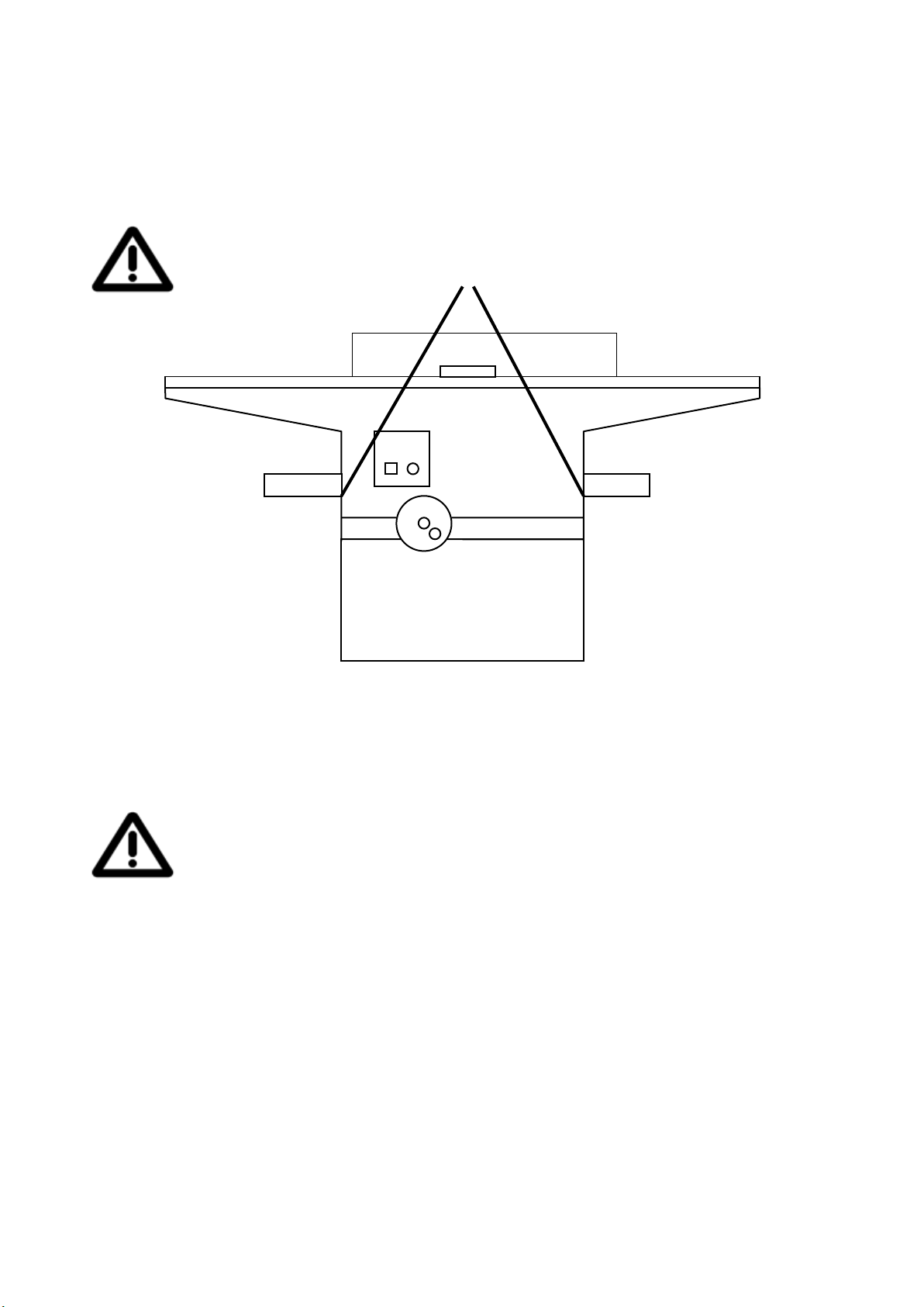
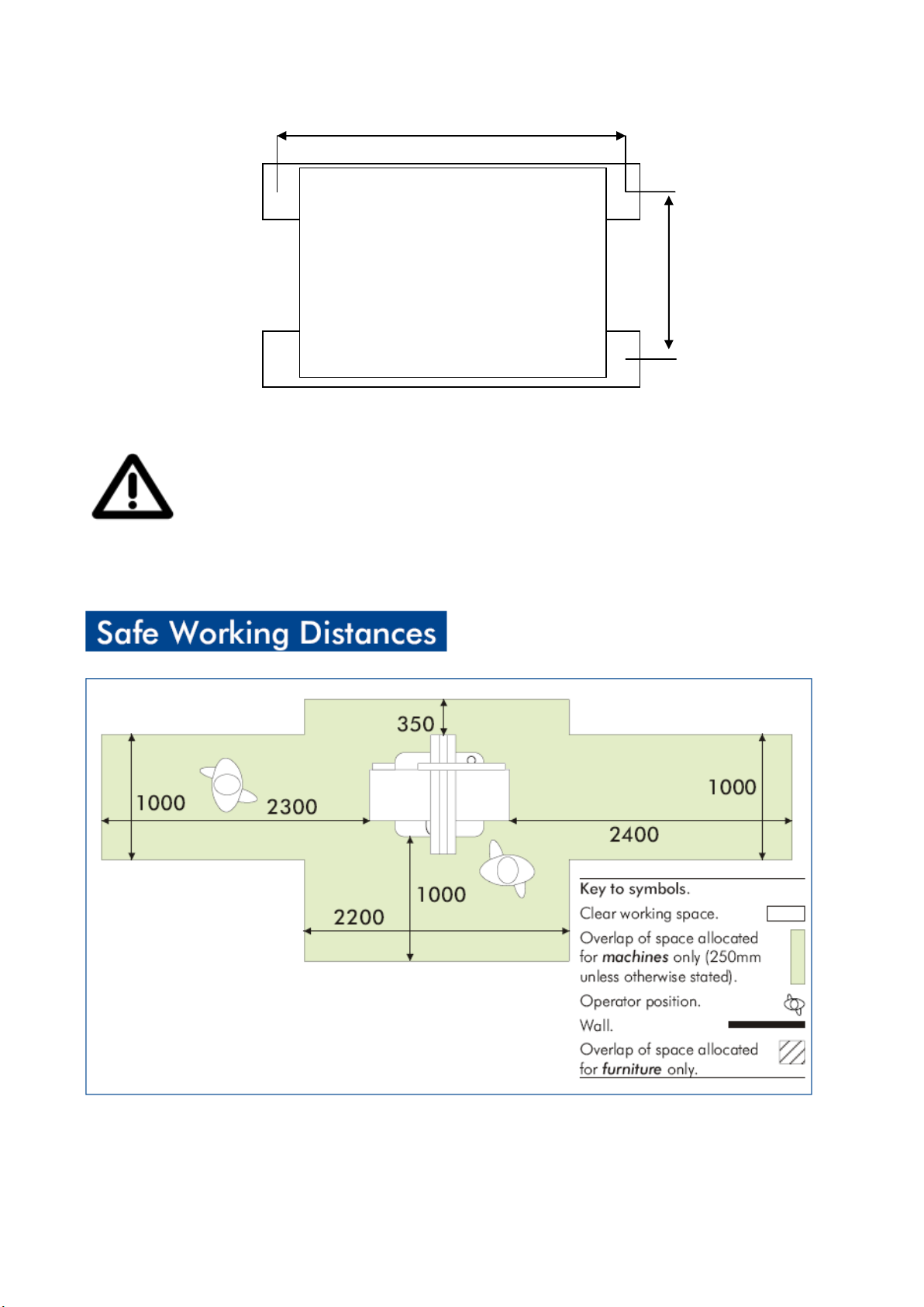
2.1 Positioning
There should be provided around every woodworking machine sufficient clear and unobstructed
space to enable the work being done at the machine to be done without risk of injury to persons
employed. You must also ensure that there is an ample power supply available, together with
good lighting and ventilation.
Only operate the machine in ambient temperatures from +10° to +40° C. If the
instructions are not followed, damage may occur during storage.
The chosen floor space should be in good and level condition to enable the machine to be
anchored at four points. Holes for M10 foundation bolts (not supplied) are provided in the
machine base. Level the tabletop by packing under the feet of the base as required. The
following drawing shows a lay-out of the anchor openings:
9
Unpacking
Dispose of the packaging materials in an environmentally friendly way and
always in accordance with local waste disposal regulations.
Remove the protective grease using turpentine or paraffin. Do not use any solvent, petrol or gas
oil, which might dull or oxidise the paintwork. Lightly oil cleaned surfaces to prevent rusting.
692mm
MB 268mm
CP 370mm

10
Storage
Keep the machine sealed in its original packaging until required for assembly/installation and be
sure to observe the machine handling advice on the outside of the packaging.
Store packed items only under the following conditions
• Do not store outdoors.
• Store in a dry and dust-free environment.
• Do not expose to aggressive substances.
• Protect from direct sunlight.
• Avoid subjecting the machine to shocks.
• Storage temperature: –10° to +50 °C
• Maximum humidity 60 %.
• Avoid extreme temperature fluctuations (condensation build-up).
• When storing for a period longer than 3 months, apply a coat of oil to all machine parts that
might be prone to rusting (corrosion protection). Regularly check the general condition of all
parts and the packaging. If necessary, refresh or re-apply a coat of anti-corrosive agent.
• If the machine is to be stored in a damp environment, it must be sealed in airtight packaging
and protected against corrosion (desiccant).
Disposal
When disposing of the machine, separate all components into material groups in order to
facilitate recycling. The main structure is made of cast iron and steel and can therefore be
safely dismantled and disposed of without risk of pollution.
Used electrical materials, electrical components, lubricants and other auxiliary
substances must be treated as hazardous waste and may only be disposed of by
specialist licenced firms.
3.0 Connection to a Dust Extraction System
This machine must be connected to a compatible dust extraction unit using a
suitable size and grade of vacuum hose.
Wood dust can be harmful to health by inhalation and skin contact, and concentrations of small
dust particles in the air can form an explosive mixture. Prevention or control of wood dust
exposure should as far as is reasonably practicable, be achieved by measure other than the
provision of personal protective equipment.
Employers have duties under the Provision of Use of Work Equipment Regulations 1998 (PUWER)
and the Control Of Substances Hazardous To Health Regulations 1988 to carry out an adequate
assessment of the possible risks to health associated with wood dust particularly when machining
hardwoods, and if necessary seek expert advice as to the method of dust extraction.
The minimum recommended air volume required to effectively exhaust this machine at
20m/sec is 1105 CMH for the MB and 1445 CMH for the CP.
11
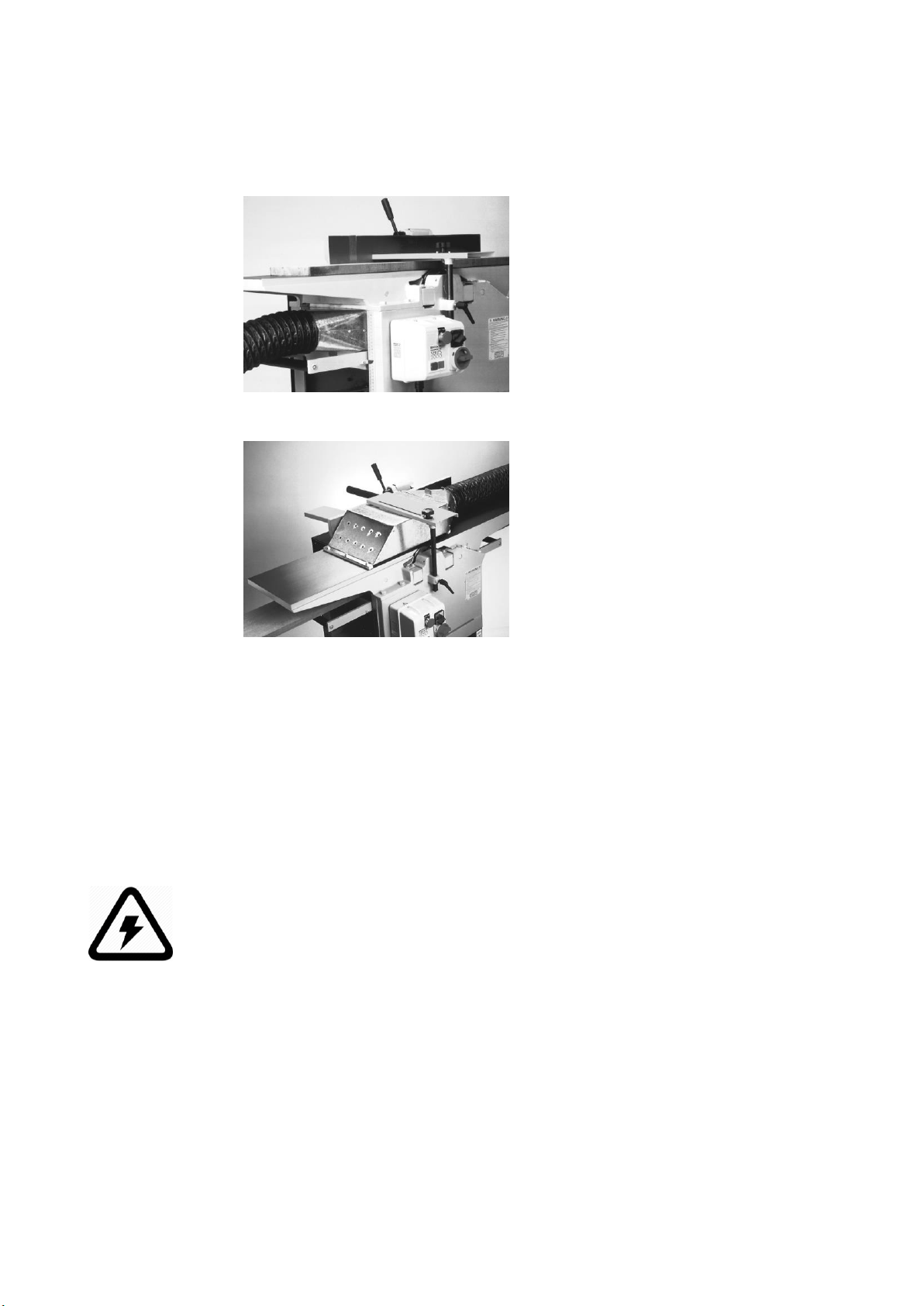
3.1 Chip Extraction Hood
A chip extraction unit is supplied as a standard feature of this machine, and guidance for its use
is as follows:
For Surfacing The hood is designed to sit on the
thicknessing bed, and should be inserted
hollow side up, with the exhaust outlet
below the fixed outfeed table. The lug
on the underside of the hood, attached
to the exhaust outlet, should locate
against the end of the thicknessing bed,
with care being taken that the anti-
kickback fingers are not fouled when
the bed is wound up.
For Thicknessing
Position the fence to the rear of the
surfacing table. Place the hood centrally
over the cutterblock, hollow side down,
with the exhaust outlet pointing toward
the in-feed table rise and fall handle.
Bring the bridge guard down over the
hood and lock it in position between the
two welded straps.
The diameter of the connection point is 125/150mm and reducers are not recommended.
Further information and references to practical guidance are contained in free leaflets from the
Health & Safety Executive, alternatively specialist help and information can be obtained from
the following:
P&J Dust Extraction Otterham Quay, Rainham, Gillingham, Kent ME8 8NA
4.0 Electrical Installation
All electrical wiring should be carried out by a fully qualified electrician and in
strict observance of the safety instructions.
Please follow these directions when connecting to the mains:
The motor and control gear have been wired in at the factory and tested before despatch. It
is prohibited to open the switch box on the machine without the express authorization of the
manufacturer. Violating this stipulation could invalidate the machine’s warranty. All that is
required is to connect the power supply to the ISOLATOR box on the machine stand.
First check that the supply details on the motor nameplate correspond with the site supply. If
the motor is operated on a voltage outside (plus or minus 6%) of the spot voltage, then
premature failure will occur.

12
Refer to the machine specification sheet at the front of the operator’s handbook to establish
the correct size of cable required. Undersize cable will lead to voltage drop at the motor
terminals.
Do not attempt to wire single-phase machines into a 13-amp plug socket.
Ensure that there is no voltage at the supply lead before connecting.
It is important to check rotation of the cutterblock which should be clockwise when viewed
from the starter side of the machine. If necessary you can change the rotation by swapping
any two of the brown wires from the supply side on the terminal block.
Should you encounter problems on start up check for the following likely causes:
PROBLEM
LIKELY CAUSE
CORRECTIVE ACTION
Fails to start
Main supply switched off
Overload tripped
Fuse blown
Loose wire
Coil failure
Check main switch
Reset overload
Check and replace fuses (check all three on three
phase)
Check all connections
Check circuit of hold in coil
Overload trips
during starting
Low voltage
Low voltage
Low voltage
Three phase machines
only: 1 fuse blown
Machine jammed
Check supply-voltage both on no load and on
moment of switch on. Allowed variation +/minus 6%
Check that correct cable size has been used to
install the machine. Change if necessary.
Long runs of cable can cause voltage drop. Check
that voltage is not outside the minus 6% tolerance.
Re-site the machine nearer supply or increase the
cable size to compensate.
It is possible for 3 phase machines to operate with
only 2 phases of the supply. This will create an
overload situation and will eventually cause
premature failure, this is known as single phasing.
Check all fuses.
Check spindle is free to rotate, clean as necessary.
Slow
acceleration
Low voltage
For a motor (particularly a single-phase permanent
capacitor motor) to reach its required starting
torque a healthy line voltage is essential.
13
5.0 Switch Gear
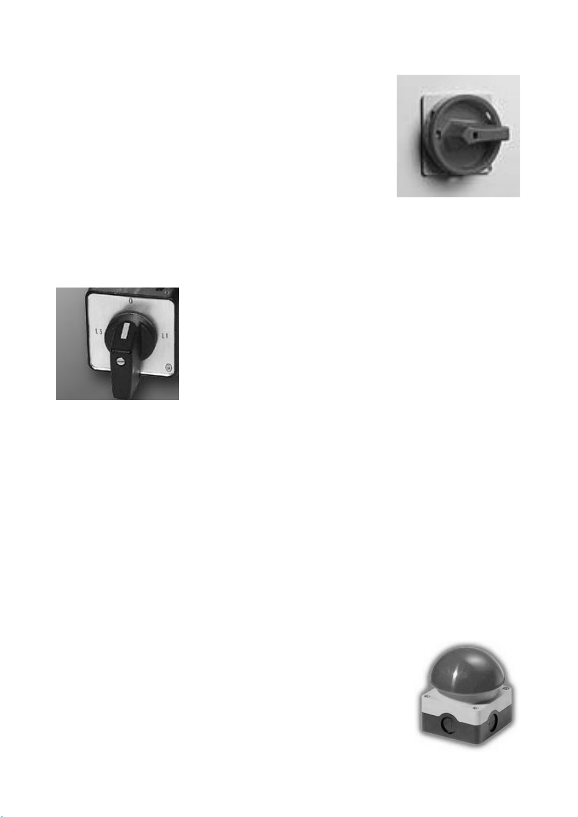
5.1 The Padlockable Isolator
With this switch in the OFF position the machine is effectively isolated
from the supply to allow personnel safe access for maintenance or
repair work and to prevent dangerous restarts. In order to prevent
unauthorised use of the machine the switch can also be secured in the
OFF position using a padlock.
To operate the machine first turn the isolator to the ON position.
5.2 Start / Stop Buttons
The cutterblock motor is then started by pushing the green (power on) button on the starter
panel, and stopped using the red (power off) button. The mushroom headed lock-off stop
switch, once pressed will remain locked in the off position. To restart the machine it is
necessary to release the off button by twisting it in a clockwise direction.
5.3 Two/Three Position Rotary Switch
The feed rollers are driven via a separate gearbox motor, which is
controlled using the rotary switch below the isolator. A single phase
machine has only two positions: ON and OFF. A three phase machine
has three:
Position 0 –OFF
Position I –Slow Run (4.5m/min)
Position II –Fast Run (7 m/min)
5.4 Circuit Protection
In case of a mains failure the starter is fitted with no volt release protection and will not restart
without being switched on again. The starter is also fitted with an overload protection device.
An electrical overload occurs where an electric motor is subjected to a greater load than it was
designed for. This can be caused by short circuit, by incorrect installation, or by misuse
(including poor machine maintenance). The inbuilt breaker will therefore help prevent damage
to the motor should such a situation occur. The motor cannot be restarted until the breaker has
reset itself.
5.5 Brake Release Switch
Machines fitted with an electro-magnetic brake unit are also equipped with a ‘Brake Release’
switch. This switch makes it possible to release the brake mechanism, allowing the operator to
rotate the cutterblock when changing or adjusting the cutting knives. To operate the switch first
turn the isolator to ON, release the mushroom headed lock off stop switch, and turn the brake
release to ‘BRAKE RELEASE’. It is not possible to start the cutterblock motor with the switch in
this position. To start the cutterblock motor turn the switch back to the
RUN position.
5.6 Optional Emergency Foot Operated Stop Switch
This switch is provided for use in emergency situations only. We do not
recommend that it is used in lieu of the mushroom headed lock-off stop
switch on the front of the starter panel.

14
6.0 Guarding
All guards should be checked at the beginning of each working shift for damage etc.
6.1 The Front Cutterblock Guard
The yellow pillar mounted guard at the front of the machine is known as the bridge guard. It is
designed for use when surfacing, and it is important that all operators are familiar with its use.
Investigations show that most accidents occur because the guard is not properly adjusted or, in
most cases, is not mounted on the machine. The guard is provided with two hand locking
arrangements, one for the vertical plane and one for the horizontal. This guard should be
maintained through regular cleaning and lubrication, and if it becomes distorted through misuse
then it should be replaced.
6.2 The Rear Cutterblock Guard
To the rear of the fence is mounted a hinged guard which is known as the rear cutterblock
guard. This is designed to guard that part of the cutterblock that is on the side of the fence
remote from the bridge guard. There is no need for its removal from the fence.
6.3 The Rear Drive Guard
The rear drive guard should only be removed for maintenance and cleaning.
6.4 The Anti-Kickback Fingers
The anti-kickback fingers are an essential safety feature of the thicknessing function. Their
purpose is to drop and lock into the face of the workpiece in the event of kickback, thereby
preventing it being ejected from the machine. The movement of the fingers may in time become
restricted due to a build-up of waste, and their freedom to move freely should be regularly
checked and cleaned as necessary.
7.0 The Cutterblock
The concept of the TERSA cutterblock is to allow the automatic clamping of the cutters using
centrifugal force. The exactness of the position is +/- 0.02mm, guaranteed on all the sharp
edges and on the whole length of the planing shaft. For correct use of the tool it is
recommended that a suitable product is used to occasionally clean the support runner of the
cutters.
To replace the knives on your MB/CP the following guidelines should be followed:
Planer knives are razor sharp. Please handle them with the utmost care,
especially when turning the cutterblock by hand.
First isolate the machine at the mains. It is not sufficient just to shut off power at the machine.
Next put up a notice saying “cutters being changed”, in case you have to leave the machine for
any reason and someone else might try to use it not knowing the knives are loose. Clean off any
15
chippings and dust from the machine tables and move the fence and front cutterblock guard out
of the way.
Points to check on the cutterblock are
1. Excessive wear of the block surface.
2. Damage or distortion to the block.
3. Damage to the threads on the retaining screws. Rounded corners within the allen heads.
4. The condition of the bearings - check for movement and listen for noisy bearings.
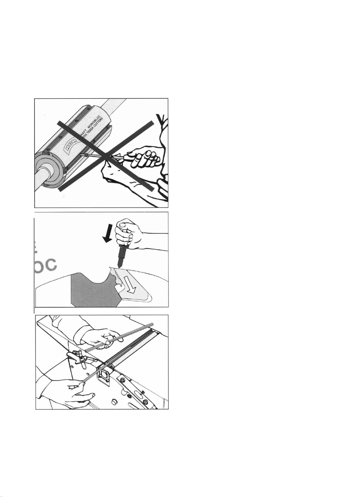
AT NO STAGE SHOULD YOU ATTEMPT TO
UNTIGHTEN THE CUTTERBLOCK SCREWS.
TO DISENGAGE THE CUTTERS WITHIN THE
BLOCK FIRST DISCHARGE THE GIBS USING THE
BRASS HAMMER PROVIDED.
SLIDE THE BLUNT KNIFE FROM OUT OF THE
SIDE OF THE CUTTERBLOCK AND EITHER
REINSERT IT WITH AN UNUSED SIDE UP OR
REPLACE IT WITH A NEW ONE.
16
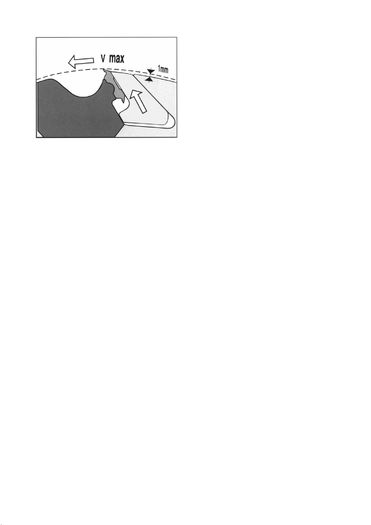
THE CUTTERS WILL AUTOMATICALLY CLAMP
ON START UP. IN ORDER TO ENSURE THAT
THEY ARE CORRECTLY SEATED THICKNESS A
300 OR 410mm WIDE PIECE OF TIMBER
INTENSIVELY ACROSS THE FULL CUTTING
SURFACE.
8.0 Preparation of the Workpiece
In preparation for all processes, examine the workpiece carefully for faults that may affect the
machining process, particularly foreign bodies such as nails, staples etc. There are many
different kinds of timber, with many different working characteristics. A skilful wood machinist
must consider the grain direction, the shape of the timber, whether it is bowed or twisted, and
the positions of defects such as knots, wavy edges etc. He should also consider any other
peculiar characteristics of the material, such as salicaceous or calceous deposits, which could
cause severe blunting and chipping of the cutters. If a number of abrasive pieces are to be
planed, use the ends of the cutter rather than the middle if possible.
8.1 Pilot Checks
Details on the correct setting of the guards, fence etc., together with the use of the necessary
safety devices, are detailed in the following sections of this manual. Prior to operation however
the following checks should be carried out (first isolate machine):
1. The blades are not cracked or distorted.
2. The cutterblock runs free (check by slowly turning it by hand).
3. The cutterblock guards are secure.
4. The timber is free of grit, nails or other foreign bodies.
5. The tables are free of spanners, rules etc., and that all tools are returned to their rightful
place.
9.0 Surface Planing
Caution: Ensure that all stock is clear of the blades before start-up.
When surfacing, the depth of cut is set by adjusting the height of the infeed table, using the
Surface Table Rise and Fall Handle.
Unlock the Surface Table Rise and Fall Lock prior to making any adjustment, and re-tighten once
set.
The outfeed table is already set level with the cutting circle of the cutterblock.
The sawn finish and the straightness of the timber determine the amount of cut required. For
normal working it is good practice to set the amount of cut to 1.5mm. When planing rough
sawn or bowed timber the amount of cut can be increased to 3mm, so as to obtain a clean finish
with one pass over the cutters.
The timber should be fed in with consideration to the grain direction. The following illustration
shows how timber fed through the cutters against the grain will cause it to tear out, producing a
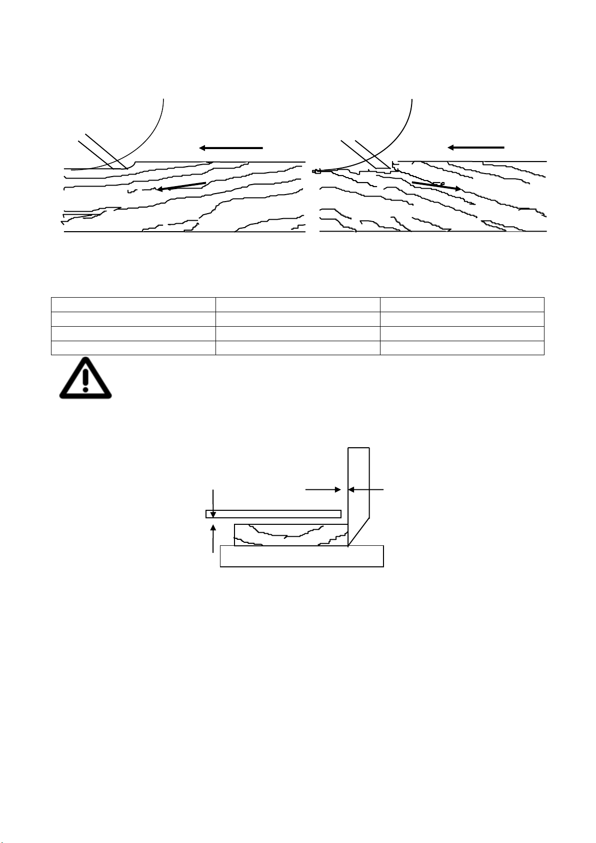
17
ragged finish. Always feed with the grain running down towards the front of the table when
in the planing mode, and the opposite when thicknessing.
Correct Incorrect
Feed Feed
Slope of grain
Slope of grain
9.1 Flatting
Workpiece dimensions:
Length
< 250mm
Only work with a push stick
>1500mm
Extn rollers or 2nd person reqd
Width
Max 308 (MB) or 410mm (CP)
Thickness
Min 10mm
If a workpiece is smaller than 10mm it may split if the depth of cut is too large
(4mm). The finished planed workpiece must not be thinner than 6mm.
When flatting, the wood is passed below the bridge guard, which should be within 10mm of the
timber and 10mm of the fence, as shown below:
10mm
Bridge Guard
10mm
Workpieces longer than the in and out-feed surfacing tables should be supported, e.g. by
extension tables or roller supports. Unless very thick material is being planed, flatting should be
the safest of operations on a hand fed planer, provided that all necessary precautions are taken.
In an attempt to justify the incorrect use of the bridge guard (many wrongly pass the timber
between the end of the guard and the fence) machinists often assert that the left hand has to
jump the guard as the wood is passed over the cutters, the consequent interruption in the
progress of the cut preventing the production of accurate work. It is also claimed that the left
hand must exert pressure on the wood immediately over the cutterblock. Only in the case of
flatting short pieces of wood might it be necessary to pass the wood between the end of the
bridge guard and the fence in order to maintain adequate control. In this event, the wood should
be fed up and over the cutters by means of a push block as described in the relevant section of
18
this manual. Small pieces are the most difficult to control, so consider, do you really need to
face and edge them?
The HSE has published guidelines on the ergonomically correct use of hand fed planers, some of
which is reproduced here:
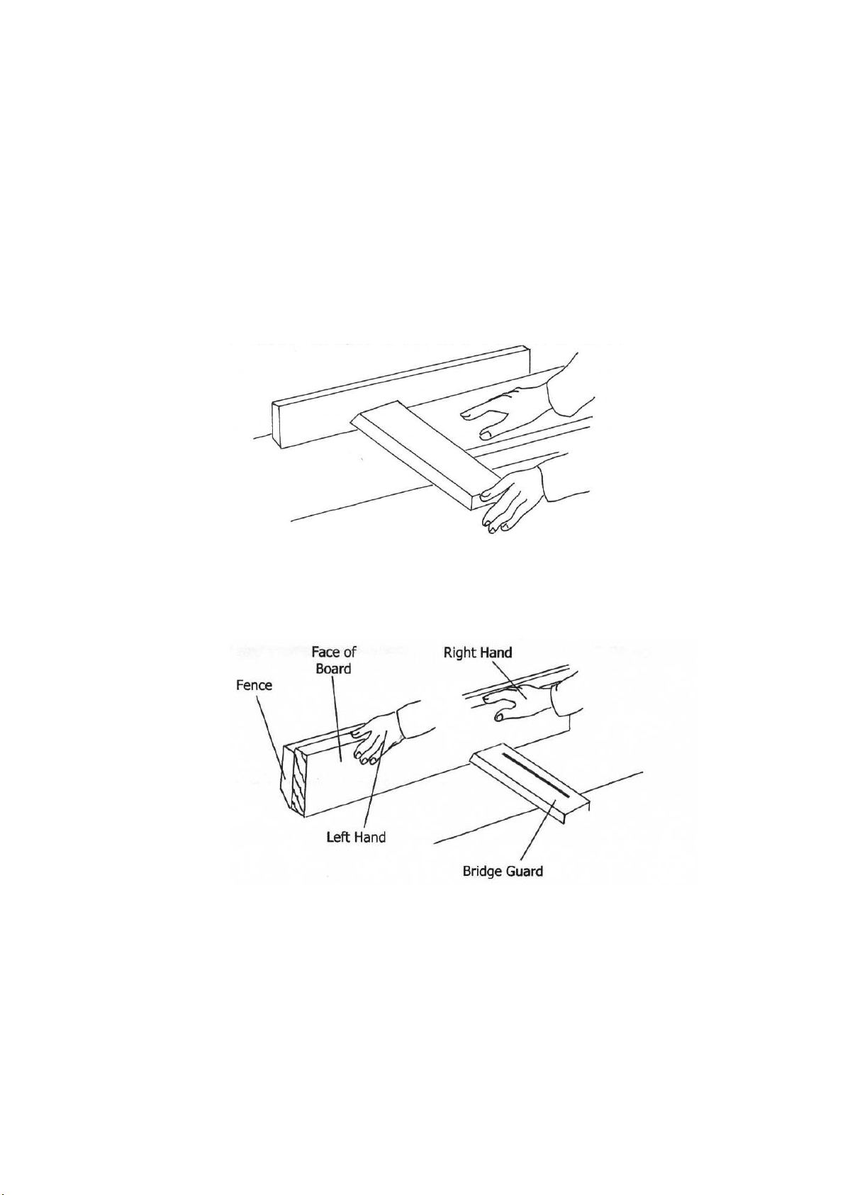
Hand positioning
Preparatory: Using the left hand, with the guard resting on the outfeed table, adjust the guard
horizontally up to the fence and then lift the guard to just accommodate the thickness of the
workpiece. Push the workpiece with the right hand only a little under the guard and let the
latter rest upon the workpiece. This stage should not be carried out while the cutterblock is in
motion.
The work should be fed by the right hand, and if the knives are sharp and the tables are properly
set the main functions of the left hand are to assist feeding by drawing the wood along the
delivery table towards the end of the cut, and to remove the planed piece.
19
When flatting a workpiece of more than 75mm thickness the bridge guard must be lowered on to
the table and adjusted horizontally to the workpiece. The workpiece should be straightened,
with flat hands beside the guard, along the fence.
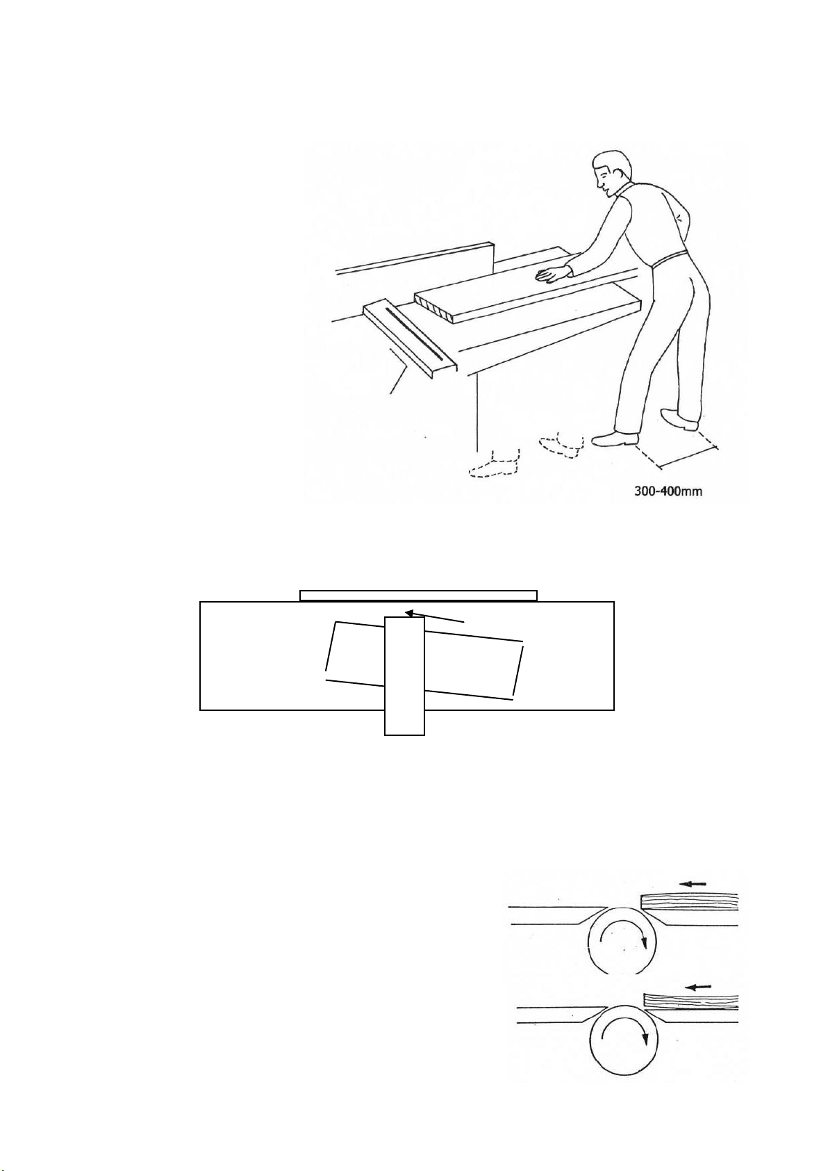
Foot positioning
It is important that a good
firm and balanced base is
made and maintained by the
feet during planing. The feet
should move forward with the
work piece giving good control
of the work piece as
illustrated in positions 1 and
2:
9.2 Planing Wide Boards
Wide boards should be fed at an angle to reduce initial impact and the risk of throwback.
Fence
10mm max
Wide board
Bridge Guard
9.3 Planing Bowed Boards
Slightly bowed boards may be planed by the method shown below, but care must be taken to
ensure two point contact on the infeed table to avoid throwback. Badly bowed boards should not
be planed in this method and should be cut up for jobs requiring shorter lengths.
Always plane the board hollow side down, as shown
Working round side down causes timber to rock,
thus making it very difficult to obtain a straight parallel
face.
20
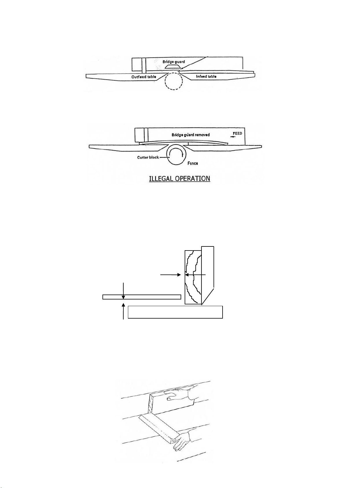
The bridge guard must always be in position when planing bowed boards, as shown:
It is illegal to operate the surface planer without the bridge guard. The long accepted way of
placing the front portion of timber on the outfeed table and taking several cuts off the other
end then reversing the timber should not be used.
9.4 Edge Planing (Squaring)
When edging, the wood is passed between the end of the bridge guard and the fence. The bridge
guard should be adjusted both horizontally and vertically to leave only 10mm from both the feed
table and the workpiece, as shown below:
10mm
Bridge Guard
10mm
When edge planing, follow these guidelines regarding the correct positioning of hands:
Preparatory: Place the workpiece against the fence and move it with the right hand forward to
about the front edge of the infeed table lip. With the left hand bring the guard up to the
workpiece. The guard should be positioned as previously shown. This stage should not be carried
out while the cutterblock is in motion.
This manual suits for next models
9
Table of contents
Other Sedgwick Industrial Equipment manuals


Popular Industrial Equipment manuals by other brands


ABB
ABB HT608965 Operation manual

ELWE
ELWE 3B SCIENTIFIC U8497460 operating manual

Spirax Sarco
Spirax Sarco U Series Installation, operation and maintenance manual

Eaton
Eaton ARCON ARC-EM/2.0 Instruction leaflet

FLENDER
FLENDER COUPLINGS N-EUPEX 3103en Assembly and operating instructions

Infranet Technologies
Infranet Technologies M2M CONTROL CX320 Technical manual