SEGUFIX 2205 User manual

1/12
SEGUF⁄X®-Foot Restraint
Versions – Item no. / identication
Item no.
Version Product features Span width* (with eyelets) Span width* (Velcro®)
mm inches mm inches
... Attachment strap: medium 1200 - 1450 47.2 - 57.1 950 - 1540 37.4 - 60.6
.../b Attachment strap: short 1000 - 1200 39.4 - 47.2 920 - 1330 36.2 - 52.4
.../e Attachment strap: long 1450 - 1700 57.1 - 66.9 950 - 1800 37.4 - 70.9
.../r Eyelet strap reinforced for higher demands
Item 2205 / Item 2305 / Item 2405
Consisting of:
2 SEGUFIX®- Foot Straps
1 SEGUFIX®- Connecting Belt
4 SEGUFIX®- Locks (key not included)
Versions: basic version / b / e / r
Item 2705 Foot Restraint Velcro®
Consisting of:
2 SEGUFIX®- Foot Straps Velcro®
1 SEGUFIX®- Connecting Belt (item 2905)
(both products with buckle lock)
Versions: basic version / b / e
3Versions SEGUFIX®-Locks:
1206 / 1208 1306 / 1308 1406 / 1408
Item 2205 Item 2305 Item 2405
The SEGUFIX®-Foot Restraint (green label) is
part of the SEGUFIX®-Bed Restraint System
and made from a cotton/rayon mix.
Component parts:
(locks and keys not included)
Item 2105 (for one foot)
Item 2005 (Connecting Belt)
Sizes: S / M / L / XL
Component parts:
Item 2805 (for one foot)
Item 2905 (Connecting Belt)
Sizes: S / M
*Span width: distance between the bed‘s attachment points / length Velcro® products: without eyelets
approx. measurements – about 8 % shrinkage possible (products are not pre-washed)
Table of Contents Page
SEGUFIX®-Foot Restraint with lock – Instructions 2 - 3
SEGUFIX®-Foot Restraint Velcro® – Instructions 4 - 5
Overview table: all versions, sizes, measurements and weights 5
SEGUFIX®-Locks and Keys 6 - 7
SEGUFIX®-Safety Information 8 - 11
Instructions for Care and Imprint 12
95°
2/12
SEGUF⁄X®-Foot Restraint
Instructions for use item 2205 / 2305 / 2405 / 2105 and 2005
Locks and keys see pages 6 and 7
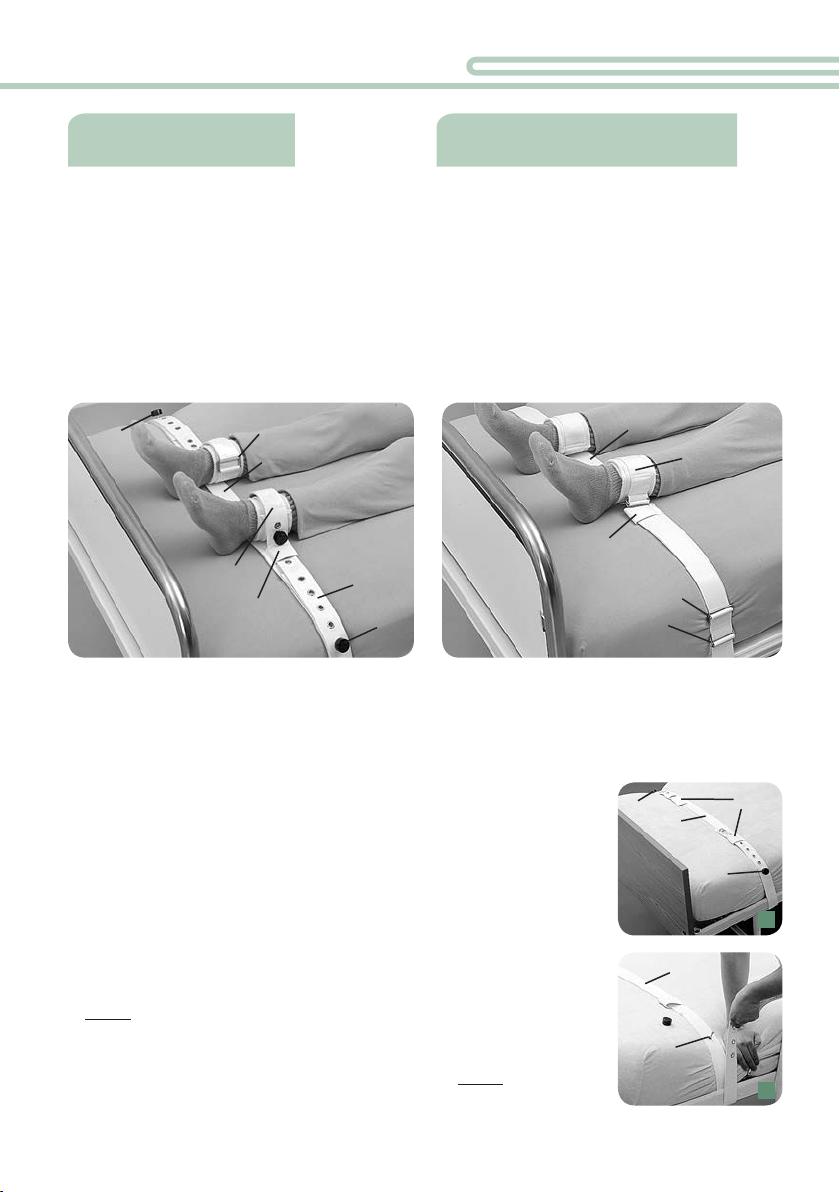
How to attach the Connecting Belt to the bed:
•Insert the pin of the lock (1) through one of the eyelets of the
pin aps.
•Lay the Connecting Belt (A) on the bed at the height of the
patient’s ankles, with the loops (B) facing up.
•Direct the end of the Connecting Belt (A) from inside out around
the bed frame or the frame of the folding part of the bed. Attach
the Connecting Belt (A) in such manner that it cannot slide along
the bed frame. Be sure to pull the Connecting Belt (A) rmly down
and then up around the frame. Then lay the Connecting Belt
tightly with one eyelet over the pin of the lock (1).
•Close the lock (1).
•Install the other end of the Connecting Belt in the same manner.
•Ensure that the Connecting Belt is installed very tightly to the bed.
Intended use:
- Gradually adjustable restraint from loose
to tight of one or both feet in bed
- Physically restraining patients
(e.g. pathology or disability that requires
restraint in a dened position in bed to
restrict patients from harming themselves
or care givers, e.g. anxiety disorders)
3 Locking Systems:
Item 2205 / 2305 / 2405
Intended use:
- Gradual positioning from loose to tight of
one or both feet in bed
- Not a restraint
(note: some jurisdictions consider Velcro®
products as a restraint, should the patient
not be able to remove them without help)
With Velcro®fastener /Buckle lock:
Item 2705
2
A
1
1
B
1
A
1
1
1A
B
D
C
2
3
A
B
C
2

3/12
How to fasten the Foot Strap to the ankle:
• Insert the pin of the lock (3) through the eyelet of the pin ap.
•Lay the foot strap (C) with the padding facing up and pointing towards the center of the
bed, and wrap it tightly around the patient‘s ankle.
•Insert the eyelet strap (D) through the metal loop (2) and pull it tightly back over the
metal buckle.
•Lay the eyelet strap (D) tightly with an
eyelet over the pin (3).
•Close the lock (3).
• The cu of the foot strap should be snug
but should not restrict blood circulation.
How to attach the Foot Strap to the Connecting Belt:
Restraining the foot in an tight position:
•Insert the eyelet strap (D) of the foot
strap through the loop (B) towards the
edge of the bed.
•Open the lock (1) and lay the eyelet
strap with an eyelet tightly over the pin
of the lock.
•Close the lock (1).
•Install the other foot strap in the same manner.
• Pull on each lock to test for a secure hold. Then lock bed side rails in an up position.
Restraining the foot gradually from tight to slack:
•Open the lock (1) of the Connecting Belt (A).
•Lay the eyelet strap (D) over the pin of the lock (1) without using
the loop (B) of the Connecting Belt. The desired mobility can be
adjusted by selecting one of the many eyelets accordingly.
•Close the lock (1).
• Pull on each lock to test for a secure hold. Then lock bed side
rails in an up position.
Follow SEGUFIX®-Safety Information
and Warnings on pages 8 - 11
How to release the restraint and remove it from bed:
See page 7 on how to open the respective locking systems.
•Open the locks (1) of the Connecting Belt and remove the straps from the pin.
• Open the locks (3) of the foot cus and remove them from the patient.
•Then remove the Connecting Belt (A) from the bed.
C
3
34
D
25
3
D
6
D
2
C
DA17
B
1B
D
18
A
3

4/12
Instructions for use item 2705, 2805 and 2905
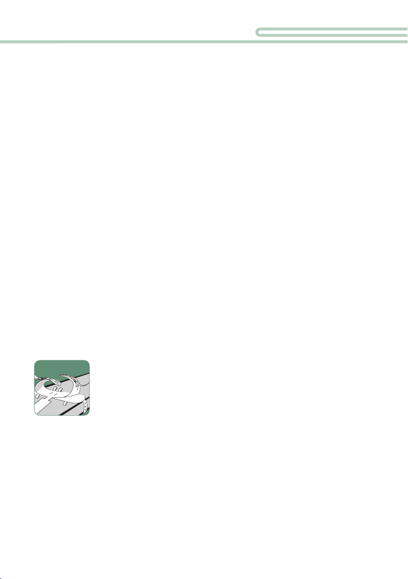
How to attach the Connecting Belt to the bed:
•Lay the Connecting Belt (A) on the bed at the height of the
patient’s ankles, with the loops (B) facing up.
•Direct the end of the Connecting Belt (A) from inside out around
the bed frame or the frame of the folding part of the bed. Attach
the Connecting Belt (A) in such manner that it cannot slide along
the bed frame. Be sure to pull the Connecting Belt (A) rmly down
and then up around the frame.
•Insert the end of the Connecting Belt through the buckle lock
and pull tight.
•Install the other end of the Connecting Belt in the same manner.
•Ensure that the Connecting Belt is attached very tightly to the bed.
How to fasten the Foot Strap to the ankle:
• Wrap the foot cu (C) with the padding facing up and pointing towards the center of
the bed tightly around the patient‘s ankle.
•Insert the strap (D) through the buckle
lock (1) and pull tight.
• The cu of the foot strap should be snug
but should not restrict blood circulation.
How to attach the Foot Strap to the Connecting Belt:
Restraining the foot in an tight position:
•Insert the strap (D) of the foot strap through the loop (B) towards
the edge of the bed.
•Pull the strap tight and attach it to the buckle lock (2) of the
Connecting Belt (A).
•Install the other foot strap in the same manner.
•Test the buckle lock for a secure hold.
Then lock bed side rails in an up position.
Restraining the foot gradually from tight to slack:
•Attach the strap (D) directly to the buckle lock (2) of the
Connecting Belt (A), without using the loop (B) of the Connecting
Belt. Now the desired mobility may be adjusted innitely.
•Test the buckle lock for a secure hold.
Then lock bed side rails in an up position.
How to release the restraint and remove it from bed:
•Undo the buckle locks (2 and 1), open Velcro®fasteners, and remove the restraint.
•Undo the buckle locks (3) and remove the Connecting Belt from the bed.
Follow SEGUFIX®-Safety Information and Warnings on pages 8 - 11
SEGUF⁄X®-Foot Restraint Velcro®
6
D
A
B2
C
4
D
A5
D
1
C3
D
1
D
A2
7
B3
1
A3
B
2
2
Buckle lock

5/12
WARNING: Read the Safety Information prior to using the SEGUFIX®-Foot Restraint.
• The SEGUFIX®-Foot Restraint with Velcro®fastener is not a restraint. It is possible for the
patient to open the Velcro®fastener and buckle lock. Note: some jurisdictions consider
Velcro®products as a restraint, should the patient not be able to remove them without help.
• Note that attachment straps and moving mechanics of the bed or mattress may interfere
with each other, causing damage, loss of function and injury.
• For more product info visit us online at www.segux.com or www.segux-shop.com
*Span width: Distance between
the attachment points on the
bed
Tables: approximate measure-
ments – about 8 % shrinkage
possible (products are not
pre-washed)
SEGUFIX®-Connecting Belt
(item 2005 / item 2905, with buckle lock)
Size Spacing between loops Number
of loops
mm inches
S 210 - 320 8.3 - 12.6 4
M 320 12.6 2
L 400 15.8 2
SEGUFIX®-Foot Restraint Span width* (with eyelets)
Size Item kg Item kg Item kg Connecting Belt kg mm inches
S 2205 0,66 2305 0,75 2405 0,75 2005 0,24 1200 - 1450 47.2 - 57.1
M 2205 0,78 2305 0,82 2405 0,82 2005 0,28 1200 - 1450 47.2 - 57.1
L 2205 0,80 2305 0,84 2405 0,84 2005 0,28 1200 - 1450 47.2 - 57.1
S 2205/b 0,68 2305/b 0,77 2405/b 0,77 2005/b 0,20 1000 - 1200 39.4 - 47.2
M 2205/b 0,74 2305/b 0,82 2405/b 0,82 2005/b 0,24 1000 - 1200 39.4 - 47.2
L 2205/b 0,76 2305/b 0,84 2405/b 0,84 2005/b 0,24 1000 - 1200 39.4 - 47.2
S 2205/e 0,73 2305/e 0,82 2405/e 0,82 2005/e 0,30 1450 - 1700 57.1 - 66.9
M 2205/e 0,84 2305/e 0,88 2405/e 0,88 2005/e 0,34 1450 - 1700 57.1 - 66.9
L 2205/e 0,85 2305/e 0,89 2405/e 0,89 2005/e 0,36 1450 - 1700 57.1 - 66.9
S 2205/r 0,73 2305/r 0,82 2405/r 0,82 2005/r 0,24 1200 - 1450 47.2 - 57.1
M 2205/r 0,84 2305/r 0,88 2405/r 0,88 2005/r 0,34 1200 - 1450 47.2 - 57.1
L 2205/r 0,86 2305/r 0,90 2405/r 0,90 2005/r 0,34 1200 - 1450 47.2 - 57.1
XL 2205/r 0,88 2305/r 0,92 2405/r 0,92 – – 1200 - 1450 47.2 - 57.1
S 2205/rb 0,74 2305/rb 0,83 2405/rb 0,83 2005/rb 0,28 1000 - 1200 39.4 - 47.2
M 2205/rb 0,84 2305/rb 0,88 2405/rb 0,88 2005/rb 0,34 1000 - 1200 39.4 - 47.2
L 2205/rb 0,86 2305/rb 0,90 2405/rb 0,90 2005/rb 0,34 1000 - 1200 39.4 - 47.2
XL 2205/rb 0,88 2305/rb 0,92 2405/rb 0,92 – – 1000 - 1200 39.4 - 47.2
S 2205/re 0,79 2305/re 0,88 2405/re 0,88 2005/re 0,32 1450 - 1700 57.1 - 66.9
M 2205/re 0,90 2305/re 0,94 2405/re 0,94 2005/re 0,40 1450 - 1700 57.1 - 66.9
L 2205/re 0,92 2305/re 0,96 2405/re 0,96 2005/re 0,38 1450 - 1700 57.1 - 66.9
XL 2205/re 0,94 2305/re 0,98 2405/re 0,98 – – 1450 - 1700 57.1 - 66.9
SEGUFIX®-Foot Restraint Velcro®Span width* (Velcro®)
Size Item kg Connecting Belt kg mm inches
S 2705 0,60 2905 0,36 950 - 1540 37.4 - 60.6
M 2705 0,68 2905 0,36 950 - 1540 37.4 - 60.6
S 2705/b 0,58 2905/b 0,32 920 - 1330 36.2 - 52.4
M 2705/b 0,60 2905/b 0,32 920 - 1330 36.2 - 52.4
S 2705/e 0,62 2905/e 0,40 950 - 1800 37.4 - 70.9
M 2705/e 0,70 2905/e 0,38 950 - 1800 37.4 - 70.9
SEGUFIX®-Foot Restraint / Foot Restraint Velcro®
Size Width of strap Ankle girth
mm inches mm inches
S 45 1.8 170 - 250 6.7 - 9.8
M 45 1.8 220 - 300 8.7 - 11.8
L 45 1.8 270 - 330 10.6 - 13.0
XL 45 1.8 300 - 380 11.8 - 15.0

6/12
SEGUFIX®-Patent Twist
locking system green
Item Consisting of:
1306 1 Patent Twist Button green
1 Square Pin
1308 1 Patent Twist Key yellow
1304 1 Patent Twist Button green
1305 1 Square Pin
Push locking system
Item Consisting of:
1406 1 Push Button
1 Push Pin
1408 1 Push Lock Key
1404 1 Push Button
1405 1 Push Pin
Intended use of the Lock:
Closing of the SEGUFIX®systems.
Intended use of the Key:
Quick release of the locks.
Caution: Each locking system only works
with its own component parts and is not
interchangeable with other locking systems.
SEGUFIX®-Magnetic
locking system black
Item Consisting of:
1206
1 Magnetic Button black /
segux.com
1 Metal Pin
1208 1 Magnetic Key red
1204 1 Magnetic Button black /
segux.com
1205 1 Metal Pin
1209 1 Magnetic Key red
with key ring
SEGUF⁄X®-Locks and Keys
WARNING: Read the Safety Information prior to using the SEGUFIX®-Locks and Keys.
• Do not submerge locks in any type of liquid. This can cause malfunction.
• Locks and keys must not be laundered.
• Test locks for proper function before each use.
• Examine the head of the pin for damage (wear and tear, rounding o or deformation).
• When closing the lock make sure that the button locks securely onto the pin. You
should not be able to pull the button o of the pin.
• When opening locks, ensure movement between the upper and lower points of contact
(item 1206). Therefore each lock can hold up to a maximum of 4 belt layers (exception:
products with “r” or “f” in the item number have thicker belts. These allow for a maximum
of 3 belt layers!). When using the Patent Twist Lock (item no. 1306) use no more then
4 belt layers. When using the Push Lock (item no. 1406) use no more then 3 belt layers.
• If damaged locks fail to open, straps can be cut with scissors or belt cutters.
• For more product info visit us online at www.segux.com or www.segux-shop.com

7/12
How to close the Locks:
•Set the respective button with the opening onto the pin so that it locks in place.
• Now test the lock for a secure hold: You should not be able to pull the button o
of the pin.
Caution: Each locking system only works with its own component parts and
is not interchangeable with other locking systems.
Follow SEGUFIX®-Safety Information
and Warnings on pages 8 - 11
Instructions for use: SEGUFIX®-Locks and Keys
Item 1206 / 1208 (SEGUFIX®-Magnetic locking system black)
Item 1306 / 1308 (SEGUFIX®-Patent Twist locking system green)
Item 1406 / 1408 (Push locking system)
How to open the Locks:
Item 1206 / 1208
•Set the red Mag-
netic Key with a
light push on top
of the black Mag-
netic Lock.
•Lift both the Mag-
netic Key and the
Magnetic Button
o of the Metal Pin (g. 1).
Item 1406 / 1408
•Push the two pins
of the Push Lock
Key into the holes
on top of the
Push Button to
unlock.
•Lift both the Push
Lock Key and the
Push Button o
of the Push Pin (g. 2).
Item 1306 / 1308
•Set the yellow
Magnetic Twist
Key on top of the
green Magnetic
Twist Lock.
•Unlock the Patent
Twist Lock by
turning the Patent
Twist Key, and then lift both the Patent
Twist Key and the Patent Twist Button o
of the Square Pin (g. 3).
13
2
8/12
SEGUF⁄X®-Safety Information
The following instructions for use are only applicable to original SEGUFIX®products.
Do not use the SEGUFIX®-Restraint and Positioning System until you have read and
understood the instructions for use.
Only use up-to-date instructions and keep them in a safe and readily available loca-
tion. Product and instruction must match. Failure to use this product properly can
cause serious injury or death. Your patient’s safety depends on your using the
SEGUFIX®system correctly.
1. Requirements for use
It is the user‘s responsibility to comply with all national laws. Always consider restraining
protocols of your work place and current legislation. The instructions for use must be
adhered to.
SEGUFIX®products may only be used by individuals with proper training and knowledge of
the product. Legal provisions and doctor‘s orders must be strictly observed! The attending
physician must ensure, that the patient‘s medical condition allows the application of the
SEGUFIX®system.
2. Intended use
SEGUFIX®products may only be used for the medical purposes, which they were
designed for.
3. Remove dangerous objects
Remove all objects from the reach of the patient, which could lead to injury or may damage
the belts (e.g. glasses, jewelry and sharp objects).
4. Inspect products before use
Inspect before each use for broken stitches, torn, worn out or frayed
parts and damaged eyelets. Damaged products could malfunction and
cause injury. Do not use damaged or worn out products.
5. When opening, locks may not be under tension
When opening locks, ensure movement between the upper and lower points of contact
(item 1206). Therefore each lock can hold up to a maximum of 4 belt layers (exception:
products with “r” or “f” in the item number have thicker belts. These allow for a maximum
of 3 belt layers!). When using the Patent Twist Lock (item 1306) use no more then 4 belt
layers. When using the Push Lock (item 1406) use no more then 3 belt layers.

9/12
6. Always attach Side Positioning Straps
The SEGUFIX®-Standard must always be used with the Side Positioning Straps attached.
Side Positioning Straps prevent the patient from helicoptering in bed or from getting over
the edge of the bed causing compression of the chest, possibly resulting in death.
In some cases it is possible that patients get over the edge of the bed even with the Side
Positioning Straps attached and the side rails in the up position. In these cases additional
restraint measures must be taken.
Important:Insert the Side Positioning Straps through the respective loops (according to
instructions) before securing them to the bed belt.
7. Beds, chairs and stretchers
- Only use SEGUFIX®products on beds, stable chairs and stretchers that allow the
product to be attached to, in accordance with the instructions.
- Products must be attached in such manner, that they cannot get out of place.
- Note that straps and moving mechanics of beds, stretchers or chairs (or alternating
pressure pads and the like), may interfere with each other causing damage, loss of
function and injury.
- The attachment points must be free of sharp edges.
- SEGUFIX®products do not prevent beds, chairs or stretchers from tipping over or from
unintended movement.
Helpful hints:
European standards for beds: DIN EN 60601-2-52
European standards for wheelchairs: DIN EN 12182 and DIN EN 12183
8. All side rails must be in the up position
To prevent accidents always lock side rails in the up position
(exception: 5-point-restraint).
Caution:Do not use with parted side rails except with a gap protector
that eectively prevents the patient from slipping through the gap. An
open gap could allow the patient to slip through even with the restraint
fastened possibly causing compression of the chest.
9. Monitor patients in restraints
Patients in restraints require frequent monitoring.
Aggressive, agitated or restless patients and patients in danger of
aspiration require constant monitoring.

10/12
10. Test closure-systems prior to each use
Check SEGUFIX®-Magnetic Locks black/segux.com, SEGUFIX®-Patent
Twist Locks green, Push Locks, Snap Locks, Velcro®Fasteners and
Buckle Locks for a secure hold.
Do not submerge locks in any type of liquid. This may cause malfunction.
If damaged locks fail to open, straps can be cut with scissors or belt
cutters. Check the head of the pin for signs of wear and tear (rounding o
or deformation).
11. Pacemaker Warning
A distance of 10 cm (4 inches) must be maintained between a patient’s
pacemaker and magnetic locks and keys to prevent the pacemaker from
possible malfunction (alternatively use Push Locks).
For possible interference of strong magnets with other patient implants
please refer to manufacturer’s instructions of these products.
12. Test products for correct attachment
Frequently check products for correct attachment. The straps must be secured to the
frame of the bed (or the folding part of the frame of the bed) in such a way, that they
cannot slide out of place.
13. Only use original SEGUFIX®products
For safety reasons SEGUFIX®products must not be altered or be combined with third
party products.
14. Use of SEGUFIX®products in vehicles
The SEGUFIX®-Transport Belt System does not replace the vehicle‘s legal-
ly required seat belt system. SEGUFIX®-Transport Belts may only be used
as additional support or for restraint of apatient. Make sure that the
patient can be rescued quickly in case of emergency (e.g. clearly visible
and handy belt cutters).
15. Secure but not too tight
The restraints must be fastened tightly, but not interfere with breathing or blood circulation.
Loosely fastened products may jeopardize the patient’s safety. Frequently check products
for correct position.
16. Storage
To prolong product life store belts and locking systems in dry and dark conditions at
about 20 °C.
SEGUF⁄X®-Safety Information
!
®
S
E
G
U
F
I
X

11/12
17. Flammability of SEGUFIX®-Bed Restraints
According to DIN EN 71-2 section 4.3 non-ammable.
According to DIN 75200 the burning rate is zero.
However, products may not come in contact with cigarettes or be expo-
sed to open ame, as this could permanently damage the products,and
this could lead to injury.
18. Correct sizing
Choosing the right size is of essential importance. Make sure that the size matches body
and waist sizes (refer to sizing tables). Products that are too small or too large compromise
the patient’s comfort and safety.
19. Disposal
Carton and plastic wrapping can be disposed of in recyclable disposal, defective products
in household garbage.
20. Declaration of conformity
For the declaration of conformity please visit:
https://www.segux.com/conformity_en.php
21. Expert recommandation to prevent accidents
(Prof. Dr.-Ing. U. Boenick, TU-Berlin)
1. Always use Side Positioning Straps
2. Lock non-parted side rails in the up position
(exception: ve-point-restraint)
3. The use of additional restraint elements may be necessary to eliminate bed egress.
22. Ensure prior to each use
- Test locks for a secure hold
- Visual inspection of belts, straps and eyelets
- Ensure sucient medical indication
- Check legal requirements

12/12
•SEGUFIX®-Restraints (white) are made of a cotton/rayon mix and are washable in hot
wash cycles up to 95 °C. Lower temperature and laundry nets will prolong product life.
Avoid methods that might bend metal parts of the system (e.g. laundry line, dry pressing,
rotary irons), eyelets may be damaged.
Not pre-washed, up to 8 % shrinkage. Store in a dry place.
Detergents: non-aggressive, no fabric softener, no bleach.
Dryer: delicate cycle at low temperature and preferably in the laundry net.
Disinfection: may be disinfected using chemothermal disinfection washing procedure.
Overdosing can damage the product.
•SEGUFIX®-Transport Belts (coloured/black) are made of polyester and are washable in
warm wash cycles up to 30 °C.
Avoid methods that might bend metal parts of the system (e.g. laundry line, dry pressing,
rotary irons), eyelets may be damaged. Store in a dry place.
Detergents: non-aggressive, no fabric softener, no bleach.
Dryer: delicate cycle at low temperature and preferably in the laundry net.
•SEGUFIX®-Locks and metal pins: remove all locks and metal pins before washing or
drying. Laundering will damage locks and possibly cause them to fail. Locks may be
cleaned with a damp cloth. Never submerge locks in any type of liquid.
•Velcro®Fastener: fasten before washing and drying to prevent lint buildup.
Occasionally use a sti brush to remove lint from Velcro®Fastener. Even with normal use,
Velcro®material has the tendency to collect lint. This can reduce the grip strength.
Before each use, test grip strength of the Velcro®Fastener.
•Durability: depends on the intensity of use and is prolonged by gentle laundry procedures
(detergent/laundry net).
© by SEGUFIX®-Bandagen, 2019
The general business and delivery terms
apply:
https://www.segux.com/PDFs/AGBs/
Terms_and_Conditions.pdf
Product specications subject to change.
Deviations from pictures in colour and
shape, errors and amendments excepted.
All rights reserved. Reprints or distribu-
tion using electronic systems/media, in
its entirety or in parts, with prior explicit
authorization in writing only.
All requests concerning this must be
directed at:
SEGUFIX®-Bandagen
Das Humane System GmbH & Co. KG
Allerbeeksring 33 · 21266 Jesteburg
Germany
Phone: +49 (0) 41 83 500-0
Fax: +49 (0) 41 83 500-200
E-mail: export@segux.de
www.segux.com
www.segux-shop.com
Care Instructions
Edition 15 · 2019-06
This manual suits for next models
29
Table of contents


